
Summary of Contents for Ecolab POSITRONIC IV
- Page 1 POSITRONIC IV Installation and Operation Manual 20428/0303/0804 Copyright Ecolab Inc. 2004 9448-2502...
- Page 2 This page intended to be blank.
-
Page 3: Table Of Contents
TABLE OF CONTENTS POSITRONIC IV Installation and Operation Manual PREFACE ......................1 INTRODUCTION ....................1 SPECIFICATIONS ................... 2 INSTALLATION PROCEDURES ..............5 4.1 Multiple Pump Pneumatic Controller ............5 4.2 Single Pump Pneumatic Controller ............5 4.3 Pump Shelf with Pump ................6 4.4 Anti-Siphon Valve .................. - Page 4 This page intended to be blank.
-
Page 5: Preface
70 psig (4.8 bars). Pump delivery is controlled by the air pressure setting of a regulator. Components of the Positronic IV system consist of a pneu- matic controller and an air operated double diaphragm pump. Required accessories include a foot valve, anti-siphon valve... -
Page 6: Specifications
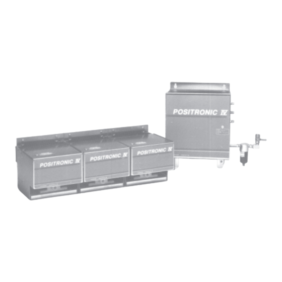
SPECIFICATIONS Figure 1 3.1 Dimensions 3.3 Equipment Supplied The Multiple Pump Pneumatic Controller is supplied with a • Height: 13-1/2 in. (34.3 cm) 1/4" ball valve and 5 micron filter for the supply air. It contains • Length: 11-1/8 in. (28.3 cm) a 5 station manifold, with three stations having pump control •... - Page 7 SPECIFICATIONS (con't.) SINGLE PUMP PNEUMATIC CONTROLLER Figure 2 3.1 Dimensions 3.3 Equipment Supplied • Height: 9 in. (22.9 cm) This controller is supplied with a 1/4" ball valve and an air regulator with a 5 micron filter for the supply air, a pump control •...
- Page 8 SPECIFICATIONS (con't.) PUMP SHELF WITH PUMP Figure 3 Figure 4 3.1 Dimensions (Pump Bracket - Figure 4) 3.1 Dimensions (Pump Shelf with Pump-Figure 3) • Height: 4-3/8 in. (11.1 cm) • Height: 8-1/4 in. (21 cm) • Length: 7-3/4 in. (19.7 cm) •...
-
Page 9: Installation Procedures
INSTALLATION PROCEDURES 4.1 Multiple Pump Pneumatic Controller HINT: If this system is replacing a different system, label any control wires prior to disconnecting that will be recon- nected to the new system. Locate a practical place for the Pneumatic Controller so the air lines from the controller to the pump do not exceed 50 ft (15 meters). -
Page 10: Pump Shelf With Pump
INSTALLATION PROCEDURES (con't) To remove the tube from this type of fitting, first pull or push the gray collar towards the fitting body, then pull out the tube. 4.3 Pump Shelf with Pump The shelf may be directly mounted on a wall using the supplied wall mount anchors and screws. -
Page 11: Typical Multiple Pump Installation
TYPICAL MULTIPLE PUMP INSTALLATION... -
Page 12: Operations
OPERATIONS 6.1 Multiple Pump Pneumatic Controller Check that all pump control regulator adjustment knobs are in the full counter-clockwise position. Check that the pump intake probes are in the appropriate products. Open the air inlet ball valve. Refer to Figure 11. While pressing the manual operator button on the sole- noid valve with a "pen tip", rotate the regulator adjustment knob until the pump starts (approximately 18 psig or 1.2... -
Page 13: Troubleshooting
TROUBLESHOOTING WARNING - Wear safety goggles, rubber gloves and other required protective clothing when removing the pump from its circuit. Proceed with caution when disconnecting the discharge line because it may be pressurized. When disconnecting a discharge line fitting, place a rag over the fitting to shield yourself from any possible spray. Problem Cause or Failure Mode Action... -
Page 14: Periodic Maintenance
PERIODIC MAINTENANCE Manually drain air filters monthly. These filters have an automatic drain, but a monthly check should be done. Annually replace filter element. Refer to Figure 13. Check day tank(s) for debris. Check exterior of fittings, anti-siphon valves and check valves for leaks. -
Page 15: Installation Options
PUMP SERVICING (con't.) 11. Begin assembling the discharge side by installing the valve seat. Squarely locate the valve onto the seat. While keeping the valve centered install the valve guide. Install the o-ring, manifold and secure with washers and nuts. 12. -
Page 16: Graphs And Tables
11.0 GRAPHS AND TABLES The following orifice flow rate information is to be used as a guide. ORIFICE AIR PRESS. PRODUCT FLOW RATE -psig (bar) oz/min. (cc/m) 25 (1.7) 15 (440) 30 (2.1) 17.6 (520) #56 DRILL 40 (2.8) 22.7 (670) 50 (3.4) 27.4 (810) 25 (1.7) -
Page 17: Replacement Parts
REPLACEMENT PARTS POSITRONIC IV REF. REF. PART NO. DESCRIPTION PART NO. DESCRIPTION •9448-1306 ORIFICE KIT #56 8528-9221 COIL 120/110V MAC 35 SERIES •9448-1298 ORIFICE KIT #55 8526-5007 SLND VLV 1/8 FPT 120/110V 6.5 W •8552-3108 UNION - REDUCING 8420-0351 REGULATOR AIR MAC 35A-00L •8480-4665 YAMADA DIAPHRAGM KIT...
Need help?
Do you have a question about the POSITRONIC IV and is the answer not in the manual?
Questions and answers