Table of Contents
Advertisement
Quick Links
Transconductance Amplifier
The contents and information contained in this manual are proprietary to
Guildline Instruments Limited. They are to be used only as a guide to the
operation and maintenance of the equipment with which this manual was issued
and may not be duplicated or transmitted by any means, either in whole or in
part, without the written permission of Guildline Instruments Limited.
OPERATOR MANUAL
For The
Model 7810
www.guildline.com
NOTICE
OM7810-8-00
25 August, 2023
Advertisement
Table of Contents

Related Manuals for Guildline 7810

Summary of Contents for Guildline 7810
- Page 1 NOTICE The contents and information contained in this manual are proprietary to Guildline Instruments Limited. They are to be used only as a guide to the operation and maintenance of the equipment with which this manual was issued and may not be duplicated or transmitted by any means, either in whole or in part, without the written permission of Guildline Instruments Limited.
-
Page 3: Table Of Contents
TABLE OF CONTENTS INTRODUCTION ....................... 1-1 1.1. SCOPE ................................1-1 1.2. GENERAL DESCRIPTION ..........................1-1 1.3. WARRANTY ..............................1-2 1.4. TO OBTAIN WARRANTY SERVICE ......................1-2 1.5. SPECIFICATIONS ............................1-4 1.5.1. Output Current Ranges ........................... 1-4 1.5.2. Stability Over 10 Minute Interval ........................1-4 1.5.3. - Page 4 THEORY OF OPERATION ..................4-1 4.1. INTRODUCTION ............................. 4-1 4.2. OVERVIEW ..............................4-1 4.3. INSTRUMENT CONTROL ..........................4-1 4.4. VOLTAGE INPUT CIRCUIT ........................4-2 4.5. COMPLIANCE VOLTAGE DISPLAY ......................4-2 4.6. SIGNAL FREQUENCY and INPUT VOLTAGE DISPLAY ..............4-2 4.7. OVERLOAD DETECTION and PROTECTION ..................
- Page 5 Range - Select Output Current Range ..................... 6-18 6.7.20. Range? - Display The Currently Selected Range ................... 6-18 6.7.21. SInce? - Display The Time The 7810 Was Last Reset ................6-19 6.7.22. Serial Number - Set The 7810 Serial Number ..................6-19 6.7.23.
- Page 6 OM7810-8-00 25 August, 2023...
- Page 7 LIST OF FIGURES FIGURE 1-1 : MODEL 7810 ............................1-1 FIGURE 3-1 : FRONT PANEL GUILDLINE 7810 ....................3-1 FIGURE 3-2 : INPUT TERMINALS ..........................3-2 FIGURE 3-3 : REAR PANEL GUILDLINE 7810 ....................... 3-4 FIGURE 4-1 : MODEL 7810 BLOCK DIAGRAM ..................... 4-3 FIGURE 5-1 : VERIFICATION TEST SET-UP ......................
- Page 8 OM7810-8-00 25 August, 2023...
- Page 9 LIST OF TABLES TABLE 2-1 : LINE CORD WIRING ..........................2-1 TABLE 5-1 : TROUBLESHOOTING GUIDE ......................5-1 TABLE 5-2 : REFERENCE CURRENT SHUNT SELECTION ................5-3 TABLE 5-3 : POSITIVE DC VERIFICATION VALUES ..................5-5 TABLE 5-4 : NEGATIVE DC VERIFICATION VALUES ..................5-5 TABLE 5-5 : 100 KHZ AC VERIFICATION VALUES ....................
- Page 10 OM7810-8-00 25 August, 2023 viii...
-
Page 11: Introduction
IEEE 488.2 and USB interfaces except for the main power ON/OFF switch. The 7810 operates on line power with voltages from 110, 115, 120, 220, or 240 VAC ± 10 %; and at 50 Hz or 60 Hz ± 5 %. -
Page 12: Warranty
(2) year warranty coverage. This warranty only extends to the intended original purchaser. Guildline will repair or replace any failed unit under warranty within a reasonable length of time at no additional cost to the customer. The repair action will correct any deficiencies so units shall meet all specifications. - Page 13 Website is: www.guildline.com Any 7810 Transconductance Amplifier delivered that has a product/design or safety defect which prevents the unit from meeting contract specification requirements will be modified by Guildline to eliminate the defect and ensure all specifications are met. All modifications including parts and labour will be done at no cost to the customer.
-
Page 14: Specifications
Section 1 1.5. SPECIFICATIONS 1.5.1. Output Current Ranges Current Range Output Current Transconductance (Full Scale) (0 % to 100 % of Full Scale) (Siemens) 5 mA 0 to 5 mA 50 mA 0 to 50 mA 10 m 500 mA 0 to 500 mA 100 m 0 to 5 A... -
Page 15: Accuracy Over 1 Year, 95 % Uncertainty
Section 1 1.5.3. Accuracy Over 1 Year, 95 % Uncertainty Accuracy (12 Months) ± (% of Reading + % of Range) 1 Hour Warm-up 100 A 50 A Selected Range 50 A to 100 A 5 A to 50 A 0.5 A to 5 A Output Currents ... -
Page 16: General Specifications
Section 1 1.5.4. General Specifications Compliance Voltage Maximum 9 Vrms, 9 VDC ± 0.05 % of Current Range in a Band from DC to 100 kHz Noise Unspecified from 100 kHz to 200 kHz Manual Operation Color Touch Screen Remote Operation IEEE 488.2 SCPI Based Instructions Dimensions (H x W x D) -
Page 17: Installation
The instrument is shipped with a three wire 15 A, 110 to 230 Volt North American line cord. The 7810 is designed for use with AC power sources between 110 to 250 Volts rated at 15 A. The detachable line cord is equipped with a NEMA 6-15 end for connection to the power source. -
Page 18: Warning
Section 2 2.4. WARNING: BEFORE SWITCHING ON THIS INSTRUMENT, THE PROTECTIVE TERMINAL OF THIS INSTRUMENT MUST BE CONNECTED TO A PROTECTIVE EARTH CONTACT. THE POWER LINE CORD SUPPLIED WILL PROVIDE THE PROTECTIVE GROUNDING WHEN INSERTED INTO A SOCKET OUTLET PROVIDED WITH AN EARTH CONTACT. -
Page 19: Manual Operation
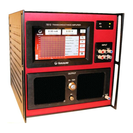
Figure 3-1 : Front Panel Guildline 7810 3.1.1. Touch Screen The touch screen is used for configuration of the 7810 ranges, control of output current and monitoring purposes. Refer to section 3.3. for touch screen displays and functions. 3.1.2. USB Interface Bus The Type A connector is used to connect the 7810 to external devices such as memory sticks, computer mice/keyboard or USB communication adapters. -
Page 20: Input
Section 3 3.1.3. Input The input consists of: a four terminal voltage input to drive the 7810, an active guard that can be used to drive the input connection cable shields and a circuit common connection. NOTE that connecting a device with an active guard to the 7810 guard will damage the 7810. -
Page 21: Guard
Front Panel is provided that supplies a signal that can be used to guard an output cable shield. If this Guard is used, only the 7810 side of the output cable shield should be connected. -
Page 22: Rear Panel
Figure 3-3 : Rear Panel Guildline 7810 3.2.1. Power Entry The power entry provides the means to connect the 7810 to a power source as well as a means of turning the power to the 7810 on and off. Protection against excessive drain on input power is provided by the integrated 15 A circuit breaker. -
Page 23: Usb Interface Bus
3.3. FRONT PANEL TOUCH SCREEN OPERATION The 7810 Graphical User Interface (or GUI) is provided on a Windows Embedded PC which is built into the instrument. The interface utilizes the touch screen interface with on screen keyboard for user control and entry. The user interface software utilizes the full screen as a “Metro” style application common to Windows 8 and newer. -
Page 24: Main Screen
3.4. MAIN SCREEN The main screen, as shown below, is where you have access to all user features of the 7810 Transconductance Amplifier. The screen has operator functions available mainly to the right hand side of the screen with statistics in the middle of the screen and graph to the left. The graph will automatically adjust the scale such that all data will be visible up to a maximum length of hours as defined in the Setup GUI screen. - Page 25 The “Exit” button simply exits the 7810 Transconductance Amplifier Graphical User Interface. The 7810 will continue to maintain the settings of the last configuration even if the GUI is not running. As shown above all screens can be easily accessed starting from the main screen, with the exception of the screens which affect the calibration of 7810.
-
Page 26: Setup Screen
3.5. SETUP SCREEN The “Data Logging Interval” field is where the operator can set the rate in which the 7810 updates the graph and statistics. The rate is expressed in seconds. The “Detailed Graph Length” field is where the operator can set the length in time that the graph will display and for which statistics are calculated. - Page 27 The “Incoming Interface” field is a drop menu listing all the available interfaces for connecting the 7810 Transconductance Amplifier to an external computer for remote control. More detail on how to remotely control the 7810 Transconductance Amplifier is outlined in the Remote Control Section of this manual.
- Page 28 If frequencies greater than 100 kHz are being used it is recommended to start with a lower output current (e.g. 1 A) to ensure that the 7810 will not overheat. If the 7810 is stable at higher frequencies (i.e. > 100 kHz), then gradually increase the output current until the required output current is reached.
-
Page 29: Link To Common
7810 input, and the load connected to the 7810 output. If more than one of these components connects to the safety ground of the 7810 a ground loop will be created. This can adversely affect the measurement system and should be avoided. - Page 30 LO - should be used for the –ve sense line of the input signal. GROUND – this is tied to the 7810 internal ground of the input circuit. It can be used as a passive shield for the input, or it can be tied to the external Guard of the input signal generator.
- Page 31 2) Close the 7810 program and use the PC shutdown control to power down the PC, wait until the screen goes black and the computer shuts down. 3) Shut the 7810 power down by using the switch in the upper right corner of the back panel. OM7810-8-00...
- Page 32 Section 3 OM7810-8-00 25 August, 2023 3-14...
-
Page 33: Theory Of Operation
DC to a frequency of 100 kHz. Although the 7810 will respond to frequencies up to 200 kHz there is no specification of the performance above 100 kHz. The 7810 has a wide range of output current from a minimum of 1 mA to a maximum of 100 A in 6 ranges. The instrument consists of various interconnected circuits to transform input voltages from 0 to 5 volts into stable output currents up to 100 A as described in this section. -
Page 34: Voltage Input Circuit
4.4. VOLTAGE INPUT CIRCUIT The 7810 has a four terminal input arrangement so that the effects of input lead length can be automatically compensated. This ensures that the full accuracy of the transconductance can be realized regardless of lead length and input frequency. -
Page 35: Figure 4-1 : Model 7810 Block Diagram
Section 4 Figure 4-1 : Model 7810 Block Diagram OM7810-8-00 25 August, 2023... - Page 36 Section 4 OM7810-8-00 25 August, 2023...
-
Page 37: Maintenance And Troubleshooting
Too high an inductive load. Check that input voltage is within required limits. Check that the load connected to the 7810 is not creating too large of an inductive feedback. GPIB or USB bus Incorrect bus address or bus cable not... -
Page 38: Performance Verification And Calibration
AC/DC Current Shunts with traceable calibration Guildline 7340 Digital Voltmeter Agilent 3458A Various interconnection cables and adapters 5.3.2. DC Accuracy And Stability Verification and Calibration Connect the voltage calibrator, 7810, the reference shunt and DVM as illustrated in Figure 5-1. CURRENT SHUNT 7810-AF 3458A... -
Page 39: Procedural Steps For Dc Current Verification
Section 5 Figure 5-2: Input Terminals Refer to Table 5-2 for the reference shunt to be used for specific ranges of the 7810. 7810 Range Reference Current Shunt (Ohms) 5 mA 7340-0.01A (100) 50 mA 7340-0.1A (10) 500 mA 7340-1A (1) 7340-10A (0.1) - Page 40 Section 5 Select + 5 V output on the voltage calibrator and record a series of 50 samples of DVM readings over a 10 minute period allowing a few minutes for the readings to stabilize. Repeat step 3 with a selection of – 5 V for the voltage calibrator. Repeat steps 1 to 4 for each other range from 50 mA to 100 A.
-
Page 41: Table 5-3 : Positive Dc Verification Values
Section 5 Mean of Std. Dev. of Mean Test Test Current Shunt DC Mean Test Test Current Range Current Current Stability Resistance Current Error Tolerance Readings Readings Error Stability Tolerance (mA, A) (Ohms) (Volts) (mA, A) 5 mA 0.0382 0.0035 50 mA 0.0382 0.0035... -
Page 42: Procedural Steps For Ac Current Verification
Section 5 5.3.4. Procedural Steps For AC Current Verification Turn on the voltage calibrator, DVM and 7810 and allow the system to warm up for a minimum of 30 minutes before proceeding. Set the calibrator output range to “Locked” at the 11 V range (or a range higher than 5 V) so the range does not automatically switch while measurements are being taken. -
Page 43: Table 5-5 : 100 Khz Ac Verification Values
Section 5 Mean of Std. Dev. of Mean Test Test Current Shunt DC Mean Test Test Current Range Current Current Stability Resistance Current Error Tolerance Readings Readings Error Stability Tolerance (mA, A) (Ohms) (Volts) (mA, A) 5 mA 0.075 0.009 50 mA 0.08 0.009... -
Page 44: Table 5-7 : 10 Khz Ac Verification Values
Section 5 Mean of Std. Dev. of Mean Test Test Current Shunt DC Mean Test Test Current Range Current Current Stability Resistance Current Error Tolerance Readings Readings Error Stability Tolerance (mA, A) (Ohms) (Volts) (mA, A) 5 mA 0.075 0.009 50 mA 0.08 0.009... -
Page 45: Remote Control
6.2. IEEE-488 (GPIB) INTERFACE The 7810 is fully programmable for use on the IEEE standard 488.1 interface bus (also known as the General Purpose Interface Bus (GPIB)). The interface is also designed in compliance with the supplemental standard IEEE-488.2. Devices connected to the bus in a system are designated as talkers, listeners, talker/listeners, or controllers. -
Page 46: Controller
Section 6 6.2.1. Controller There can be only one designated controller in charge on the IEEE-488 bus. This device exercises overall bus control and is capable of both receiving and sending data. The rest of the devices can be designated as listener, talker or talker/listener. The controller can address other devices and command them to listen, address one device to talk and wait till the data is sent. -
Page 47: Address And Talk/Listen Selection
The IEEE-488 Address and Talk/Listen status can be set using the front panel controls as directed by the operator menu system. If there is no controller and the 7810 is hooked up to a printer for hard copy, then Talk Only mode should be selected as the preferred mode of operation. -
Page 48: Table 6-2 : Ieee-488 Pin Designations
Section 6 NAME DESCRIPTION DIO1 Data Input Output Line 1 DIO2 Data Input Output Line 2 DIO3 Data Input Output Line 3 DIO4 Data Input Output Line 4 End or Identify Data Valid NRFD Not Ready for Data NDAC Not Data Accepted Interface Clear Service Request Attention... -
Page 49: Ieee-488 Input Buffering
(MAV) bit will be set in the status register. 6.2.9. IEEE-488 Deadlock If the controller demands a byte of data from the 7810 and the buffer is empty, the 7810 will set the Query Error flag in the Event Status Register. -
Page 50: Rs-232C Responses
(such as using VERBion instead of VERSion). No command used in the 7810 has an embedded space in its name, spaces (0x20) are used only to separate command names from their parameters. -
Page 51: General Syntax For Numbers
Section 6 command parser of the 7810 is case insensitive (i.e. the letter case of commands sent to the 7810 does not matter), both UPPER case letters and lower case letters may be used. 6.4.2. General Syntax For Numbers Numeric parameters may have up to 30 characters, and although the 7810 will accept numeric parameters in the range ±2.2E-308 through ±1.8E308, the useful range of numbers... -
Page 52: Remote And Local Operation
REMOTE AND LOCAL OPERATION The 7810 can be operated using the front panel keys or it can be operated remotely using a remote controller. In addition, the 7810 can be placed in a local lockout condition at any time by a command from the controller. -
Page 53: Programming Command Summary
Section 6 From IEEE-488 Interface RS-232C Interface Command Command Local Remote MLA + REN REMOTE Local / Lockout LLO + REN LOCKOUT Remote Local LOCAL Remote / Lockout LLO + REN LOCKOUT Local / Lockout Remote / Lockout MLA + REN REMOTE Remote / Lockout Local... -
Page 54: Figure 6-1 : Event Status Bit Operation
Section 6 Figure 6-1 : Event Status Bit Operation OM7810-8-00 25 August, 2023 6-10... -
Page 55: Remote Commands
This command clears all Event Status Registers summarized in the status byte register. All queues, except the Output Queue, that are summarized in the status byte register are emptied. The 7810 is forced into the Operation Complete Idle State and the Operation Complete Query Idle state. -
Page 56: Table 6-5 : Event Status Register
User Request - Set when any key is depressed on the 7810 keyboard. Power On - This bit is set after the 7810 is powered up. Table 6-5 : Event Status Register OM7810-8-00... -
Page 57: Idn? - Identification Query
(4) fields delimited by commas (,). The first field is the manufacturer (i.e. Guildline Instruments), the second field is the model (i.e. 7810), the third field is the serial number (i.e. 72065), and the final field is the firmware revision (i.e. A). -
Page 58: Opc - Operation Complete
Section 6 6.7.6. *OPC - Operation Complete This command will cause the 7810 to set the Operation Complete bit (bit 0) in the Event Status Register. Since the 7810 processes all commands sequentially, the operation complete bit will be set as soon as the command is parsed. -
Page 59: Sre - Service Request Enable Command
This Register can be read by Serial Poll or by the *STB? command. 6.7.13. *TST? - Query Results Of Self Test This command is intended to report the status of any self-tests performed by the 7810. If the 7810 passes all of its self-tests then the reply will be 0. -
Page 60: Date? - Display The 7810 Internal Date
Section 6 6.7.15. Date? - Display The 7810 Internal Date This command will report the date maintained in the system real time clock in the terse format: YYYY/MM/DD or if verbose mode is enabled: Date YYYY/MM/DD where YYYY, MM and DD are the year, month and day respectively. -
Page 61: Operate - Set The Operation State
NAME DESCRIPTION AnaLogue Overload - This bit is set to indicate that the 7810 has detected an analogue overload condition (Input voltage >100 % fsc). Compliance Over Voltage - This bit is set when the amplifier compliance voltage capability has been exceeded. -
Page 62: Operate? - Display The Current Operation State
Section 6 6.7.18. Operate? - Display The Current Operation State This query command displays the value of the current operation state. In verbose mode the reply will be: Operate 1 or in terse mode the reply will be: where the value 1 is dependent upon the current operation state. 6.7.19. -
Page 63: Since? - Display The Time The 7810 Was Last Reset
Section 6 6.7.21. SInce? - Display The Time The 7810 Was Last Reset This query command will display the date and time at which the 7810 was last powered up (or reset). The verbose reply will be: SInce Thurs June 2, 10:55:22 1988... -
Page 64: Verbose - Set Verbose Mode
This mode should be used for determining problems with programs and when the instrument is being used interactively. For example, the command: VErbose will place the 7810 into verbose mode. 6.7.26. Volt - Select The Input Voltage Range This command changes the currently selected input voltage range. For example the command: Volt 5V will select the 5V input range where the value 5 is dependent on the range desired.
Need help?
Do you have a question about the 7810 and is the answer not in the manual?
Questions and answers