Advertisement
Quick Links
PA2T3K
Thank you for purchasing the Beat-Sonic PA2T3K Plug & Play Power Amplifier. Designed
and made in Japan, this product represents our commitment to quality and excellence.
Please read this manual carefully prior to installing this product to ensure correct operation.
■ Features
- Designed for Toyota 28-pin / 10-pin radio connectors
- Class AB high efficiency car audio amplifier
- Easy to install plug & play installation
- Retains factory head unit, speakers and connectors
- Manufactured using premium hi-fi audio grade components
- Made in Japan
■ Important
- This product is installed using the factory harness connectors, however there are multiple
factory harness connectors of the same size and shape. Do not plug into the wrong connector
or serious damage may result. Contact Beat-Sonic if unsure.
- Check the Beat-Sonic website for the latest vehicle compatibility information before installing.
- Some vehicles may require extensive disassembly to install this product. Installation should be
performed by an experienced motor vehicle technician or auto electrical professional.
■ Precautions
- This amplifier is suitable for negative ground 12V DC operation only.
- Wrap cables in protective electrical tape when routing near metal brackets and sharp edges.
- Do not install main unit or harness near moving mechanisms such as the steering column,
seat rails, pedals etc.
- Do not install this product where it may get wet or in areas where it is likely to get dusty or dirty.
- Do not open, disassemble or modify this product.
- Ensure the car battery is in good condition. A weak battery will cause a significant drop in
power output and sound quality.
■ Protection Circuit
This amplifier is provided with a protection circuit that operates in the following conditions:
- When the speaker output terminals are short circuited
- When the battery is connected in reverse polarity
- When the amplifier is overheated
If this occurs, turn off the ignition and determine the cause of the malfunction. In case of
overheating, wait until the amplifier has cooled off before using.
■ Contents
PA2 Main Unit x 1
Wiring Harness x 1
Instruction Manual x 1
Padding Strips x 2
1 Specifications
Class AB amplifier
4 channels
Power output
45W x 4ch (4Ω)
Speaker impedance
4 ~ 8Ω
Input sensitivity
0.5 ~ 5V
15 ~ 80kHz (+0, -1dB)
Bandwidth
Total harmonic distortion
0.01% (1kHz / 4 Ω )
Operating voltage
DC11V ~ 15V
Quiescent current
200mA
Fuse
15A
Audio input
AUX (Line Level RCA)
Speaker High Level
Short circuit / reverse polarity / heat protection
Protection
96mm (W) x 114mm (D) x 40mm (H)
Dimensions
Weight
420g (exc. harness)
2
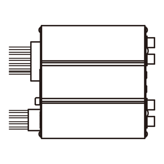
Parts Location
High Level
①
②
③
REAR
FRONT
GAIN
R
F
⑤
⑥
⑦
⑧
Instruction Manual
Double Sided Tape x 2
Carpet Mounting Tape x 2
① Power Indicator
② Power / Speaker Output Connector
Input
③ Fuse (15A)
PA2
④ High Level Input Connector
④
⑤ Rear Channel RCA Input
⑥ Rear Channel Gain
⑦ Front Channel Gain
⑧ Front Channel RCA Input
3
Connection Diagram
NO:000003
28-pin
connector
10-pin
Factory
connector
head unit
Connect Cable A to
leftmost connector
ATTENTION : 28-PIN CONNECTOR
The factory head unit has multiple
identical 28-pin connectors.
Connect Cable A to the leftmost
connector only.
4
Installation
4.1 Remove all necessary parts to gain access to the rear of the factory head unit. The
method of disassembly varies for each vehicle. If unsure, please contact Beat-Sonic
for advice for vehicle specific instructions.
4.2 Viewing the head unit from the rear, locate the leftmost 28-pin connector and the
adjacent 10-pin connector. Disconnect the leftmost 28-pin connector and 10-pin
connector from the back of the factory head unit and connect the PA2T3K connectors
inline with the factory connectors in a daisy chain configuration (see section 3).
10-pin
connector
4.3 Attach the chassis ground terminal to the mounting bracket for the factory head unit.
Loosen one of the fasteners using the correct size socket or spanner then slide the
chassis ground terminal underneath before retightening the fastener.
Chassis Ground
Cable A
Chassis Ground
Diagram for illustration purposes.
Actual radio and panels will vary
according to model and grade.
Photos are for illustration purposes.
Actual radio, number of connectors
and connector positions will vary
according to model and grade.
28-pin
connector
Factory
head unit
Factory
28-pin
connector
Factory
10-pin
connector
16-pin
connector
(grey)
PA2 Amplifier
8-pin
connector
(white)
Advertisement

Related Manuals for Beat-Sonic PA2T3K

Summary of Contents for Beat-Sonic PA2T3K
- Page 1 4.2 Viewing the head unit from the rear, locate the leftmost 28-pin connector and the adjacent 10-pin connector. Disconnect the leftmost 28-pin connector and 10-pin connector from the back of the factory head unit and connect the PA2T3K connectors inline with the factory connectors in a daisy chain configuration (see section 3).
- Page 2 USA and Canada 14778 Beach Blvd. La Mirada, CA 90638 TEL: 1-714-994-1085 FAX: 1-714-249-4741 Minimum gain position Maximum gain position Factory set gain position Beat-Sonic USA Inc. www.beatsonicusa.com email: info@beatsonicusa.com (approx. 7 o’clock) (approx. 5 o’clock) (approx. 12 o’clock)
Need help?
Do you have a question about the PA2T3K and is the answer not in the manual?
Questions and answers