Advertisement
Quick Links
NW6000-7501 QIG
1. Overview
NW6000-7501 DNV GL Certi ed Managed PoE+ Switch is designed for
harsh environments to withstand vibration, shock, free fall and power
surges. The switch provides layer 2+ software features while operating
from a 24/48VDC power source, and has DNV GL Marine Approval and
Lloyd's Register Group Approval for safe and reliable marine
operations. It includes 8-port 10/100/1000Mbps PoE+ downlink and
4-port GbE SFP uplink with 30W per PoE+ port for powered devices.
2. Package Checklist
The switch is shipped with the following items*.
If any of these are missing or damaged, please contact your customer
service representative for assistance.
• The Switch x 1
• DIN-Rail kit x 1
• Console Cable x 1
• Quick Installation Guide x 1
Panel view
POST
ALM
RPS
PWR
SFP
9
10
11
12
1
2
3
PoE
5
6
7
Grounding
Screw
1
+
PWR
+
RPS
3
Power Input
ALM
Terminal Block
5
OFF
ON
DIP Switches
ALM
1
1
PWR
2
7
2
RPS
Reset
9
11
Top View
Front View
-1-
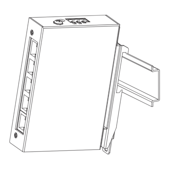
3. Mounting and Dismounting to DIN-Rail
!
Mounting the switch
Place the switch on the DIN-Rail from above using the slot, push the
front of the switch toward the mounting surface until it snaps into
place with a click sound.
Dismounting the switch
Press the switch from top and pull out the lower edge of the switch
and then remove the switch from the DIN-Rail.
Mounting the Switch
!
4. Grounding the switch
SFP
Grounding and wire routing help limit the e ects of noise due to
PoE
4
8
electromagnetic interference (EMI). Run the ground connection from
the ground screw to the grounding surface prior to connecting
1000Mbps
1000
devices.
(Green)
2
!
4
6
8
LNK/ACT
(Green)
LNK/
ACT
5. Wiring requirements
10
SFP
12
!
ATTENTION:
The Switch is an open type device and shall be DIN-Rail
mounted or wall mounted (optional) in the cabinet and
the ambient temperature should not exceed the operating
temperature.
Click
Removing the Switch
ATTENTION:
A corrosion-free mounting rail is advisable. When installing,
make sure to allow for enough space between devices to
properly install the cabling. And provide ample space for
air flow.
ATTENTION:
This product is intended to be mounted to a well-grounded
mounting surface such as a metal panel.
WARNING:
Safety measures should be taken before connecting the
power cable. Turn o
the power before connecting
modules or wires. The correct power supply voltage is
listed on the product label. Check the voltage of your
power source to make sure that you are using the correct
-2-
voltage. DO NOT use a voltage greater than what is speci ed on
the product label. Calculate the maximum possible current in each
power wire and common wire. Observe all electrical codes
dictating the maximum current allowable for each wire size. If
current exceeds the maximum rating, the wiring can overheat
causing serious damage to your equipment.
Please read and follow these guidelines:
• Use separate paths to route wiring for power and devices. If
power wiring and device wiring paths must cross make sure the
wires are perpendicular at the intersection point.
NOTE: Do not run signal or communications wiring and power
wiring through the same wire conduit. To avoid interference,
wires with di erent signal characteristics should be routed
separately.
• You can use the type of signal transmitted through a wire to
determine which wires should be kept separate. The rule of
thumb is that wiring that shares similar electrical characteristics
can be bundled together
• You should separate input wiring from output wiring
• We advise that you label the wiring to all devices in the system
5.1 Wiring Power Input
5.1.1 The Switch with terminal block
You can use "PWR" for Primary Power input and "RPS" for Redundant
Power Input. Check the polarity while connecting.
Top view of Terminal Block is shown in the gure below:
!
Caution:
• Use copper conductors only
• Wiring cable temperature should
support at least 105°C
• Tighten the wire to a torque value 5lb
• The wire gauge for the terminal block
Terminal Block
should range between 12~24 AWG
To insert power wire and connect the speci ed voltage range at a
maximum of 6A DC power to the power terminal block, follow the
steps below:
1. Use a flat-head screwdriver to loosen the wire-clamp screws
2. Insert the negative/positive DC wires into the PWR-/PWR+
terminals, respectively
3. Tighten the wire-clamp screws to prevent the wires from loosening.
ATTENTION:
!
Please use a power supply from 24~57VDC, the device
power shall be supplied by SELV circuit.
NOTE: We strongly request that each Industrial PoE switch connects
to the individual power supply. Please don't use one power supply to
two or more PoE switches at a time.
-3-
Advertisement

Summary of Contents for Seas of Solutions NetWave NW6000-7501
- Page 1 voltage. DO NOT use a voltage greater than what is speci ed on 3. Mounting and Dismounting to DIN-Rail the product label. Calculate the maximum possible current in each ATTENTION: power wire and common wire. Observe all electrical codes The Switch is an open type device and shall be DIN-Rail dictating the maximum current allowable for each wire size.
- Page 2 5.2 Wiring the relay contact (ALM) Illuminated Port link-up LNK/ACT (Green) Blinking Activity (receiving or transmitting data) The switch has one set of relay alarm (1~8 Port disconnected or link failed RJ45 port) output. This relay contact uses two Illuminated Port link-up contacts of the terminal block on the (Green)
Need help?
Do you have a question about the NetWave NW6000-7501 and is the answer not in the manual?
Questions and answers