
Summary of Contents for MOREK DC30kW
- Page 1 Installation and Configuration Manual Morek EV DC Chargers 30 kW ev.morek.eu v_3.23.11...
-
Page 2: Table Of Contents
Contents 1. Safety Instructions......................3 1.1 Symbols used in this manual ................. 3 1.2 Save these instructions ..................3 1.3 WARNING: Risk of electric shock ................3 1.4 WARNING: Accumulation of gases ................ 4 1.5 CAUTION ....................... 4 1.6 Charging station safety precautions............... 4 1.7 Safety Labels on the packaging ................ - Page 3 6 Install Morek DC 30KW ....................24 6.1 Handling ....................... 24 6.2 Installing a cabinet ....................24 6.3 Open the door of Morek DC 30KW ..............24 6.4 Electrical Connections ..................25 6.5 Check after Installation ..................26 7. Commissioning......................27 7.1 Preparation for Power on ..................
-
Page 4: Safety Instructions
1. Safety Instructions Read and observe the following safety precautions before you install, service, or use your Morek charging station. The installer must ensure that the charging station is installed in accordance with the relevant country-specific standards, and local regulations. -
Page 5: Warning: Accumulation Of Gases
⚫ This charging station contains no user-serviceable parts. The user must not attempt to service, repair, or relocate the charging station. Contact Morek or your distributor for more information. ⚫ Make sure that the charging cable cannot be damaged (kinked, jammed, or driven over) and that the plug(s) do not come into contact with heat sources, dirt, or water. -
Page 6: Safety Labels On The Packaging
• This charging station contains no user-serviceable parts. The user must not attempt to service, repair, or relocate the charging station. Contact Morek or your distributor for more information. • Make sure that the charging cable cannot be damaged (kinked, jammed, or driven over) and that the plug(s) do not come into contact with heat sources, dirt, or water. - Page 7 On the packaging Caution Packaging and internal items shall be protected from rain and moisture. On the packaging Caution Packaging is prohibited from stacking On the packaging Warning Keep upright! On the packaging Warning Handle with care...
-
Page 8: Introduction
Morek DC 30KW installation. © 2023 Morek - all rights reserved. No part of this document may be modified, reproduced, processed, or distributed in any form or by any means, without the prior written permission of Morek. -
Page 9: Product Introduction
2.3 Product Introduction Morek DC 30kW EV charging station optimizes the use of space by charging up to vehicles simultaneously using CCS2. User friendly design with 7’’ touch screen. -
Page 10: Product Specification
2.4 Product Specification 3-phase+neutral+PE 400VAC ± 10% Input Voltage Input Current 0~58A Frequency 50Hz AC INPUT ≥0.99 Power Factor ≤5% Input THDi Output Voltage 150~1000V Output Power 30KW Output Current 0~100A ≤±0.5% Voltage Regulation Accuracy OUTPUT ≤±1% Current Regulation Accuracy Charging Type MODE 4 ;... -
Page 11: List Of Tools
Some operations described in this manual may require a ladder or a stepladder. Refer to your local regulation regarding the working height and relevant safety instructions. Below is the list of the tools required (not included) to install Morek DC30kW charging station: ⚫... -
Page 12: Product Features
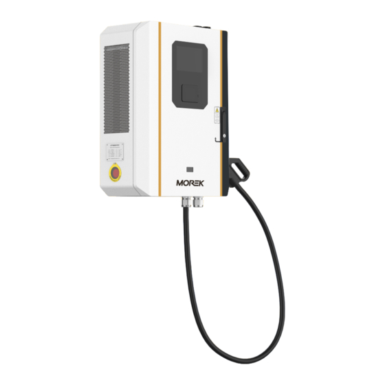
3. Product Features 3.1 Product Parts Illustration Description Z shaped waterproof shutter. 7’’ display screen. RFID reader / card terminal (depending on the configuration). Charging connector (CCS2). Emergency stop button. Visible window (PTB meter display window depending on the configuration, Optional). Stainless steel metal lock head Charge cable 3.2 Nameplate... -
Page 13: Transport And Storage
4. Transport and Storage 4.1 Storage WARNING: Condensation inside the cabinet damages the charger. • Only transport and store the charging station in its original packaging. No liability can be accepted for damage incurred when the product is transported in non-standard packaging. -
Page 14: Packaging Removal
2. Manual Materials handling Two persons are required to move one cabinet at a time. 4.4 Packaging Removal CAUTION: Some operations described in this manual may require a ladder or a stepladder. Refer to your local regulation regarding the working height and relevant safety instructions. 1. - Page 15 4.Remove the left and right side covers. 5.Remove the front and back covers. 6.Remove the wrapping film wrapped around the cabinet. 7.Remove the PE plastic bag over the cabinet. 8.Remove the EPE cushioning blocks around the cabinet. 14 /...
-
Page 16: Supplied Components
4.5 Supplied Components The packaging includes the following components: ⚫ Charging station ⚫ Accessories 15 /... -
Page 17: Preparation For Installation
The charger is intended for location in a non-restricted area. 5.4 Parking space placement To achieve the maximum cable length, it is recommended to place Morek DC 30KW as described below. 16 / 41... - Page 18 Note: Leave adequate free space in front of the charging station to ensure that users can interact with the touchscreen and other interfaces safely and comfortably. Note: Leave at least 600 mm on both side of the charger in order to ensure the connector is accessible. 17 / 41...
-
Page 19: Cooling
Note: Bollards should not interfere with the clearance around the charger. 5.5 Cooling The air inlet is located at the bottom of the cabinet, and the air outlet is located on the left side of the cabinet. 1. Air inlet; 2. Air outlet 18 / 41... -
Page 20: Implantation Plan
Note: In locations with harsh weather conditions (high temperatures, snow, strong sun conditions,...), it is recommended to ensure additional protection such as canopy or roof protection. 5.6 Implantation plan 5.6.1 Column installation The opening size of the equipment is shown in the figure: 19 / 41... -
Page 21: Wall Mount Installation
5.6.2 Wall mount installation The opening size of the equipment is shown in the figure: 20 / 41... -
Page 22: Route Power Supply Cables
Explanation: 1. The installation position of the charging pile shall be determined according to the site 2. M8 stainless steel expansion bolt (length not less than 60mm), it must be perpendicular to the foundation surface, and ensure that 3 to 4 silk teeth are exposed after the nut is tightened. -
Page 23: Protection Against Electric Shock And Short Circuits
5.8 Protection against electric shock and short circuits Protection against electric shock The charging station contains the following devices to protect against electric shock: IMD (Insulation Monitoring Device). On outlet CCS2. • Surge protector • MCB for AC Input • Leakage protection device for AC input •... -
Page 24: Grounding Instructions
5.9.2 Grounding Instructions Observe the following rules for the grounding instructions: • Ground impedance must be lower than 20 ohms in dry conditions where the charging station is installed. 23 / 41... -
Page 25: Install Morek Dc 30Kw
After the cabinet is installed, shake the cabinet from different directions. Do not feel obvious loosening or shaking. 6.3 Open the door of Morek DC 30KW CAUTION: When opening the door, please follow the instruction next to the door lock. -
Page 26: Electrical Connections
Open the door 1. Use the key to open the lock. 2. Pull out the handle 3. Turn the handle clockwise 4. Open the door 6.4 Electrical Connections The steps to connect the cable are as follows: 1. Open the front door of the cabinet; 2. -
Page 27: Check After Installation
6.5 Check after Installation 1. Sealing According to the requirements of the design and protection level, After the AC cable is installed, lock the cable lock to prevent dust or bugs from entering. 2. Clean up Clean up the sundries inside the cabinet and around the cabinet, such as cables, binding tapes, screws, etc. -
Page 28: Commissioning
7. Commissioning Danger: Risk of Electric Shock DANGER: WARNING: Risk of electric shock. Hazardous voltages Before servicing: Before servicing, switch off the power at the main breaker (outside of the breaker) and switch off MCB in AC power supply system Electrical charge may be stored for up to 5 min after switching off!. -
Page 29: Use Of Morek Dc 30Kw
• Do not operate the charging station if it is physically damaged or if the charging cable has cracks, excessive wear, or other visible damage. Contact Morek or your distributor if you suspect that the charging station is damaged. •... - Page 30 Click on “Preparing”.it display as follow: Swipe the RFID card to start charging, and the screen shows: After vertification is failed, it will display: 29 / 41...
- Page 31 After vertification is successful, it will display: After local vertification is successful, it will display: 30 / 41...
-
Page 32: Remote Start
The charging station starts to charge the vehicle. 8.1.2 Remote start The backend could give command of start charging after the charger is connected to it 31 / 41... -
Page 33: Stop Charging
8.2 Stop charging 8.2.1 Local stop Click on the charging button. The charging information pops out and swipe the card again to stop charging process. Stop charging. Please wait. The screen returns to main menu and shows charging finished. 32 / 41... -
Page 34: Remote Stop
To check the information of charging, you may click the “Finishing” button and scan them. Put back the connector to its origin position after charging. 8.2.2 Remote stop Charging finished after backend gives command of stop charging. Displayed as follows.To check the information of charging, you may click the “Finishing”... -
Page 35: Charging By Online Or Offline
Put back the connector to its origin position after charging. 8.3 Charging by online or offline The default charging mode of the charging station is offline. Under the offline function, you can use the M1 card to start the device; online function can use 4G communication method . The specific operations are as follows: Click on the blank space at the upper left of the screen, the login interface appears, enter the password ‘301204’, click ‘Enter’, and click ‘Login’... - Page 36 Click ‘Charge Setting’, select online in ‘Authorize Mode’, click ‘Save’ and wait for the device to restart. After restarting, Click on the blank space at the upper left of the screen, the login interface appears, enter the password ‘301204’, click ‘Enter’, and click ‘Login’ to enter the settings main interface again.
- Page 37 Click “System Setting”, click “CSCU setting”, input the station number provided by the platform (if any), input the Platform Address of the platform. Click “Save”, the TCU set successfully and wait for the device to restart. Choose static IP or DHCP as WAN type: 36 / 41...
-
Page 38: Decommissioning
Secure the power supply cabinet and put up warning signs to prevent accidental supply of power. To remove Morek DC 30KW charging station, follow the installation steps listed above in reverse order. Dispose of the charging station in a responsible manner. -
Page 39: Preventive Maintenance
10. Preventive Maintenance For safe operation of the charger and to ensure a continuous and adequate level of service for users, regular maintenance and control of the equipment is required. In addition to these regular maintenance operations, in case a fault or suspected fault, a corrective maintenance operation must be performed. -
Page 40: Troubleshooting
11. Troubleshooting Fault Analyze Troubleshooting Emergency stop button Rotate and reset the emergency was pressed stop button The monitoring system AC contactor not detected there was a contacting fault in the system and Find out the system fault forced it to be disconnected The input and output terminals of the... - Page 41 Damaged electricity Replace the meter meter Monitoring unit failure Replace the monitoring unit The front door or the Check whether the fault left and right doors are disappears after the front door or not closed the left and right doors are closed Use a multimeter to measure The insulation of the whether the impedance between...
Need help?
Do you have a question about the DC30kW and is the answer not in the manual?
Questions and answers