Advertisement
Description
Demonstration circuit 2438A is an isolated USB data
transceiver featuring the
features an EMI optimized circuit configuration, including
an isolated DC-DC converter, and printed circuit board
layout. All components for data signaling and isolation
are integrated into the LTM2894 using LTC's isolator
µModule
technology. The demo circuit operates from a
®
performance summary
SYMBOL
PARAMETER
V
Operating Supply Range (Isolated Power Input)
CC
V
Operating Supply Range (USB Bus Power
BUS
Input)
V
Input Operating Range (DC-DC Off)
CC2
V
Input Operating Range (DC-DC On)
CC
Output Voltage
t
Low Speed Data Rate
LDR
t
Full Speed Data Rate
FDR
V
Maximum Working Insulation Voltage
IORM
Common Mode Transient Immunity
operating principles
The LTM2894 demo board includes an isolated DC-DC
converter delivering power to V
6V from the input supply V
maintained by the separation of GND and GND2 where
significant operating voltages and transients can exist
without affecting the operation of the LTM2894. The logic
side is enabled upon connection of a USB cable via the
LTM2894 ON pin. All logic side signals are referenced to
the logic supply pin V
LO
supply inputs, V
and V
CC
more than 200mA from V
an external supply of 6V to 7V. V
LTM
2894. The demo circuit
®
Specifications are at T
CONDITIONS
V
BUS
V
CC
GND to GND2
at approximately
CC2
and/or V
. Isolation is
CC
BUS
. The LTM2894 has two power
. For applications requiring
BUS
, V
must be connected to
CC2
CC
may be connected
BUS
DEMO MANUAL DC2438A
7.5kV
supply on V
and/or V
CC
ates an unregulated isolated output voltage on V
regulated 5V for USB communication on V
Design files for this circuit board are available at
http://www.linear.com/demo/DC2438A
L, LT, LTC, LTM, Linear Technology, µModule and the Linear logo are registered trademarks of
Linear Technology Corporation. All other trademarks are the property of their respective owners.
= 25°C
A
= 4.4V, I
= 200mA
CC2
= 6V, I
= 500mA
CC2
to USB bus power to enable data communication. If the
isolated DC-DC converter is not needed then V
be driven by an external voltage.
Upstream USB signaling is controlled by the bidirectional
+
pins D1
and D1
configured dependent upon the connected downstream
peripheral device. For full speed operation a 1.5k pull-up is
+
asserted on D1
stream USB data pins, D2
15k pull-down resistors.
LTM2894
Isolated USB
RMS
Data Transceiver
. The DC-DC converter gener-
BUS
MIN
TYP
4.4
6
4.4
5
6
4.4
5.5
5.5
1.5
12
1414
1000
50
–
. A 1.5k pull-up resistor is automatically
, for low speed mode on D1
+
–
and D2
, each have integrated
and
CC2
.
BUS2
MAX
UNITS
45
V
5.5
V
45
V
7.5
V
V
V
Mbps
Mbps
V
DC
V
RMS
kV/µs
may
CC2
–
. The down-
dc2438af
1
Advertisement
Table of Contents

Related Manuals for Linear Technology DC2438A


Summary of Contents for Linear Technology DC2438A
- Page 1 LTM2894 using LTC’s isolator µModule technology. The demo circuit operates from a L, LT, LTC, LTM, Linear Technology, µModule and the Linear logo are registered trademarks of ® Linear Technology Corporation. All other trademarks are the property of their respective owners.
-
Page 2: Operating Principles
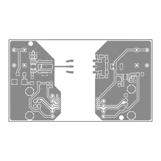
0 100 200 300 400 500 600 700 800 900 1000 parasitic capacitance. FREQUENCY (MHz) DC2438a F01 Figure 1. DC2438A Radiated Emissions Quick start proceDure Demonstration circuit 2438A is easy to set up and evalu- 2. Connect USB cable from computer to input side (J1) of ate the performance of the LTM2894. - Page 3 DEMO MANUAL DC2438A Quick start proceDure Figure 3. Layer 1 Top Layer Figure 4. Layer 2 Bottom Layer dc2438af...
-
Page 4: Parts List
DEMO MANUAL DC2438A parts list ITEM REFERENCE PART DESCRIPTION MANUFACTURER/PART NUMBER Required Circuit Components IC, LTM2894IY LINEAR LTM2894IY#PBF Hardware: For Demo Board Only Cap, Tantalum 4.7μF 10% 2312 50V AVX TAJC475K050RNJ Cap, Ceramic 180pF 5% 0603 100V C0G AVX 06031A181JAT2A C3, C6 Cap, Ceramic 4.7µF 10% 1210 50V X7R... -
Page 5: Schematic Diagram
Information furnished by Linear Technology Corporation is believed to be accurate and reliable. However, no responsibility is assumed for its use. Linear Technology Corporation makes no representa- tion that the interconnection of its circuits as described herein will not infringe on existing patent rights. - Page 6 Linear Technology Corporation (LTC) provides the enclosed product(s) under the following AS IS conditions: This demonstration board (DEMO BOARD) kit being sold or provided by Linear Technology is intended for use for ENGINEERING DEVELOPMENT OR EVALUATION PURPOSES ONLY and is not provided by LTC for commercial use. As such, the DEMO BOARD herein may not be complete in terms of required design-, marketing-, and/or manufacturing-related protective considerations, including but not limited to product safety measures typically found in finished commercial goods.
- Page 7 Mouser Electronics Authorized Distributor Click to View Pricing, Inventory, Delivery & Lifecycle Information: Analog Devices Inc. DC2438A...
Need help?
Do you have a question about the DC2438A and is the answer not in the manual?
Questions and answers