Table of Contents
Advertisement
Quick Links
Advertisement
Table of Contents

Summary of Contents for Enersafe ATS-30A
- Page 1 User Guide Automatic Transfer Switch (ATS-30A) www.enersafe.cl V.1.2...
-
Page 2: Table Of Contents
2. Product Overview ..............1 3. Important Safety Warnings ..........2 4. Operation Indicators & Status ..........2 5. Installation ................4 6. Operation ................5 7. Communication Port .............. 5 8. Trouble Shooting ..............7 9. Specifications................8 10. Appendix: ................9 www.enersafe.cl... -
Page 3: Introduction
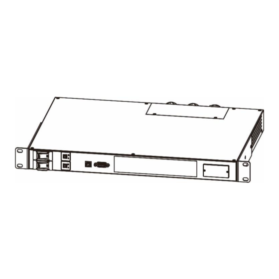
1. Introduction This ATS-30A product is designed with two independent power inlets to supply power to the load from a primary power source. Should primary power source fail, the secondary will automatically back up the connected equipment without any interruption. The transfer time from one line to another is seamless to the connected equipment. -
Page 4: Important Safety Warnings
NOTE: These instructions may be modified by the wiring regulations in force in the country where the ATS is purchased. 4. Operation Indicators & Status Source preference selector Priority setting LEDs Power source status LEDs Output source LEDs Fault indicator Alarm mute button www.enersafe.cl... - Page 5 B () Output from source A () Output Power B is output status Output from source B () Output from source A () NO OUTPUT Output from source B () Alarm not present Alarm Fault () Alarm present Continuously www.enersafe.cl...
-
Page 6: Installation
Step 3: Fasten the terminal cover and cable gland to unit. Then, customer can plug the user load to the output 10A (“Output 3”) or 16A (“Output 2”) sockets depending on user’s requirements. www.enersafe.cl... -
Page 7: Operation
PIN # NAME TYPE SIGNAL PIN # SIGNAL VBUS Serial line TX Serial line RX POWER +12V POWER NOTE: The utilization of the communication port is optional and it is not necessary for the correct functioning of the ATS www.enersafe.cl... - Page 8 ATS functioning status is regular). The following diagram shows the functioning of the contacts port. Fig. 2: Contacts port basic diagram. ATTENTION: The pins of the contact port are able to carry maximum current of 8A and maximum voltage of 250Vac. www.enersafe.cl...
-
Page 9: Trouble Shooting
The display is off There is power Contact the nearest technical support but the load is supply problem in centre. powered. display. If there is any abnormal situations occur, which doesn't list above, please call the service people immediately for professional examine. www.enersafe.cl... -
Page 10: Specifications
9. Specifications MODEL ATS-30A INPUT Input Voltage 220/230/240 VAC Acceptable Input Voltage Range 180 - 258 VAC Input Frequency 50 Hz/60 Hz Maximum Input Current 30 A OUTPUT Output Voltage 220/230/240 VAC 10 A for IEC-C13 outlets Maximum Output Current... -
Page 11: Appendix
Source B. Source B will be power source Acceptable input during this range. When input frequency for Source frequency of source B is beyond 45Hz – 55Hz this range, ATS will automatically switch to power from Source A. www.enersafe.cl...
Need help?
Do you have a question about the ATS-30A and is the answer not in the manual?
Questions and answers