Table of Contents

Summary of Contents for ACPro XK60
- Page 1 Change for life Wired Controller XK60 Owner's Manual Commercial Air Conditioners Thank you for choosing Commercial Air Conditioners, please read this owner’s manual carefully before operation and retain it for future reference.
- Page 2 User Notice Please carefully read this manual before installation and use of this product Thanks for choosing AC Pro duct type air conditioners. Please read this manual carefully ◆ before operating this product and keep it properly for future reference. In addition, please take notice of the symbols below.
-
Page 3: Table Of Contents
Contents 1 Introduction to the Wired Controller ..............1 1.1 Appearance and LCD Icons ............... 1 1.2 Introduction to the LCD Icons ..............2 2 Press Buttons ....................4 2.1 Buttons ....................... 4 2.2 Instruction to the Function of Press Buttons ..........4 3 OPERATION INSTRUCTION ................. - Page 4 3.15 E-HEATER Setting .................18 3.16 Blow Function Setting ................18 3.17 Filter Setting ...................19 3.18 Quiet Function Setting ...............21 3.19 Ultra-Dry Setting ..................22 3.20 Other Functions ..................22 4 Installation of the Wired Controller ...............24 4.1 Standard Parts ..................24 4.2 Installation Location and Installation Requirements ........25 4.3 How to Install the Wired Controller ............25 4.4 How to Remove the Wired Controller ............26 5 Error Display ....................26...
-
Page 5: Introduction To The Wired Controller
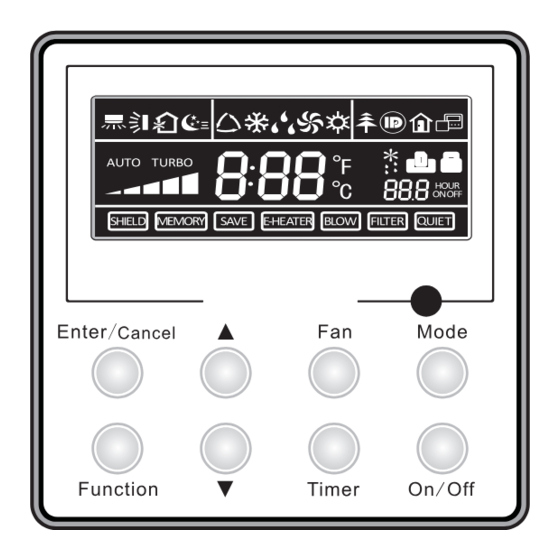
Wired Controller XK60 1 Introduction to the Wired Controller Fig.1 Appearance of the Wired Controller 1.1 Appearance and LCD Icons Fig.2 Appearance of the LCD... -
Page 6: Introduction To The Lcd Icons
Wired Controller XK60 1.2 Introduction to the LCD Icons Table 1 Icons Introduction Left and right swing function Up and down swing function Air exchange function Sleep function Auto mode COOL mode DRY mode FAN mode HEAT mode Health function... - Page 7 Wired Controller XK60 Electric heater Blow function Defrosting function Filter cleaning Timer Setting Keycard control / Detected status sensed by human body Quiet function Lock function...
-
Page 8: Press Buttons
Wired Controller XK60 2 Press Buttons 2.1 Buttons Fig.3 Press Buttons 2.2 Instruction to the Function of Press Buttons Table 2 Press Buttons Function Introduction ① .Function selection and canceling; Enter/Cancel ② .Press it for 5s to enquiry the outdoor and indoor ambient temperature. -
Page 9: Operation Instruction
Wired Controller XK60 3 OPERATION INSTRUCTION 3.1 On/off Press the On/Off button to turn on or off the unit. Notes: The state shown in Fig.4 indicates the OFF state of the unit after energization. ① . The state shown in Fig.5 indicates the ON state of the unit after energization. -
Page 10: Temperature Setting
Wired Controller XK60 3.3 Temperature Setting Press ▲ or ▼button to increase or decrease setting temperature under on-state of the unit. If press either of them continuously, temperature will be increased or decreased by 1°C every 0.5s. In Cooling, Dry, Fan and Heating mode, temperature setting range is 16°C~30°C. -
Page 11: Right And Left Swing
Wired Controller XK60 3.5 Right and Left Swing Under the ON state of unit, press the Function button to select the “Right and Left Swing” function option and then press the Enter/Cancel button to activate it. When the Swing function is activated, press the Function button to select the "Right and Left Swing"... -
Page 12: Up And Down Swing
Wired Controller XK60 3.6 Up and Down Swing Under the ON state of unit, press the Function button to select the "Up and Down Swing" function option and then press the Enter/Cancel to activate it. When the Swing function is activated, press the Function button to select the "Up and Down Swing"... -
Page 13: Air Exchange Setting
Wired Controller XK60 Cancellation of Timer Setting: The timer setting can be canceled by press “Timer”. Then , xx. Hour won’t be displayed. Timer Setting under the ON state of the Unit is as shown in Fig.11: Unit On, no timer function Press “Timer”... - Page 14 Wired Controller XK60 1――The unit continuously runs for 60min, and fresh air valve runs for 6 min. 2――The unit continuously runs for 60min, and fresh air valve runs for 12 min. 3――The unit continuously runs for 60min, and fresh air valve runs for 18 min.
-
Page 15: Sleep Setting
Wired Controller XK60 3.9 Sleep Setting Sleep on: Press the Function button under the ON state of the unit to select the “Sleep” function option and then press the Enter/Cancel button to activate it. Sleep off: When the Sleep function is activated, press the Function button to select the Sleep function option and then press the Enter/Cancel button to deactivate this function. - Page 16 Wired Controller XK60 e.g. If the setting temperature is 25°C, the temperature will rise by 1°C in each hour until it reaches 27°C. 7 hours later, the temperature will drop to 26°C. After that, the unit will run at this temperature.
-
Page 17: Health Setting
Wired Controller XK60 3.10 Health Setting Under unit on status, press “Function” button to select health function with “Health” icon flashing. Press “Enter/Cancel” button to activate health function. When health is on, press “Function” button to set function, with “health” icon flashing. Then press the “Enter/Cancel”... -
Page 18: Vacation Setting
Wired Controller XK60 Unit On, no I-Demand function Press “Function” button to set Press “Enter/Cancel” button to I-Demand function activate I-Demand function Press “Enter/Cancel” button to Press “Function” button to set cancel I-Demand function I-Demand function Fig.17 I-Demand Setting Note: The I-Demand function can be cancelled by mode switch and unit ON/OFF. -
Page 19: Turbo Function Setting
Wired Controller XK60 Unit On, no Vacation function Press “Function” button to set Press “Enter/Cancel” button to vacation function activate vacation function Press “Enter/Cancel” button to Press “Function” button to set cancel vacation function vacation function Fig.18 Vacation Setting Note: The vacation function can be only set under heating mode. -
Page 20: Save Function Setting
Wired Controller XK60 button to select the "Turbo" option and then pressing the Enter/Cancel button. Turbo function setting is as shown in Fig.19: Unit On, no Turbo function Press “Function” button to set Press “Enter/Cancel” button to turbo function activate turbo function Press “Enter/Cancel”... - Page 21 Wired Controller XK60 Cancel button to activate this function. The activated SAVE function can be deactivated by firstly pressing the “Function” button to select the “SAVE” option and then pressing the “Enter/Cancel” button. The energy saving setting is as shown in the Fig.20: Unit On, no Save function Press “Function”...
-
Page 22: E-Heater Setting
Wired Controller XK60 3.15 E-HEATER Setting E-HEATER: in the HEAT mode, “E-HEATER” function is allowed to be activated to improve the heating efficiency. Generally, it will be activated automatically as the unit goes into the HEAT mode through any button operations . -
Page 23: Filter Setting
Wired Controller XK60 Deactivation of the “Blow” Function: The activated “Blow” function can be deactivated by firstly pressing the Function button to select the “Blow” option and then pressing the Enter/Cancel button. BLOW function setting is as shown in Fig.22: Unit On, no Blow function Press “Function”... - Page 24 Wired Controller XK60 Unit On, no Filter function Press “Function” button to set filter function the pollution level Press “Function” button to set Press “Enter/Cancel” button “00” shown at the timer area filter function to activate filter function Press “Enter/Cancel” button to cancel filter function Fig.23 Filter Setting...
-
Page 25: Quiet Function Setting
Wired Controller XK60 “0” shows up at the second place, the accumulated operating hour reaches 1400h. Every increase of the number means another 400h is accumulated. When “9” shows up, it means the operating hour reaches 5000h. When the filter reaches serious-level pollution, “3” will be shown at the first place, When ④... -
Page 26: Ultra-Dry Setting
Wired Controller XK60 Unit On, no Quiet function Press “Function” button to set Press “Enter/Cancel” button to quiet function activate quiet function Press “Enter/Cancel” button to Press “Function” button to set cancel quiet function quiet function Fig.24 Quiet function setting Notes: "QUIET"... - Page 27 Wired Controller XK60 3.20.2 Memory Function Memory switchover: Under the OFF state of the unit, press the Mode and ▲ buttons at the same time for 5s to switch memory modes. When setting the memory mode, “MEMORY” will be displayed. If this function is deactivated, the unit will go to the OFF state after power recovery.
-
Page 28: Installation Of The Wired Controller
Wired Controller XK60 Unit off Simultaneously press “Function” Press “Mode” button to set till and “Timer” button for 5s, the “05” is shown on the temperature wired controller will enter displayed area. Then the unit will parameter setting interface. enter the indoor fan shutdown mode. -
Page 29: Installation Location And Installation Requirements
Wired Controller XK60 4.2 Installation Location and Installation Requirements (1). Do not install the wired controller in the damp place or under direct sunlight. (2). Do not install the wired controller close to the hi-temperature object or place where the wired controller is likely to suffer water spray. -
Page 30: How To Remove The Wired Controller
Wired Controller XK60 Brief instructions: Pull out the 2-core signal line from the mounting hole and pass this line through the round ① . hole located at the bottom of the wired controller. Use M4×25 screws to fix the soleplate of the wired controller on the wall. - Page 31 Wired Controller XK60 Error codes and their meanings: Table 5 Number Error code Error Compressor high pressure protection Indoor anti-freeze protection Compressor low pressure protection, refrigerant lack protection and refrigerant colleting mode Compressor high discharge temperature protection Communication error Indoor fan motor error...
- Page 32 Wired Controller XK60 Drive module over temperature protection Zero passage protection AC current protection Drive current error Sensor connecting protection Temperature drift protection Bus low voltage protection Bus high voltage protection Charge loop error Input voltage abnormality Drive memory chip error...
- Page 33 AC Pro, Material Supply Inc. Add: 17700 Industry Ave Fontana, CA 92337 Tel: (800) 800 4121 www.acpro.com...
Need help?
Do you have a question about the XK60 and is the answer not in the manual?
Questions and answers