
Related Manuals for VendNet CB500-SA

Summary of Contents for VendNet CB500-SA
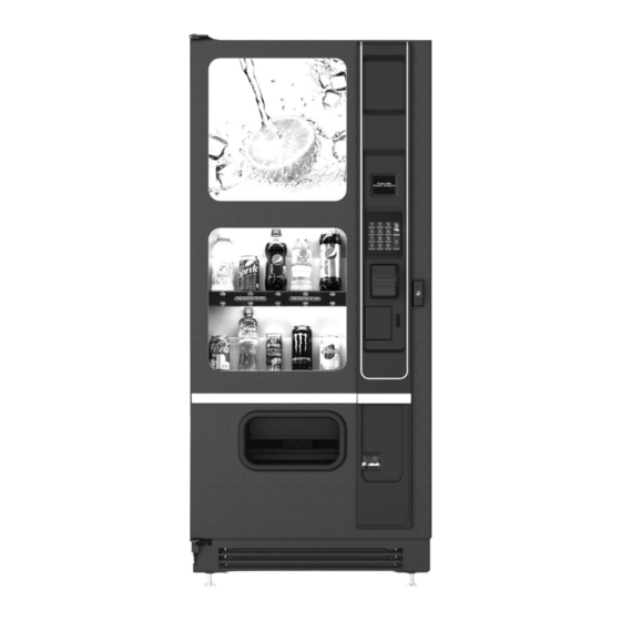
- Page 1 CB500-SA CAN/BOTTLE VENDOR MODEL: 3578 / 3578A 3578G SERVICE VendNet MANUAL 8040 University Boulevard Des Moines, IOWA 50235 United States of America 4214690 • E OCT 2021...
-
Page 3: Table Of Contents
TABLE OF CONTENTS INTRODUCTION ........................1 SPECIFICATIONS ......................... 2 ELECTRICAL ..............................2 REFRIGERATION ............................2 CAPACITY ..............................2 SIZE ................................2 FEATURES ..............................2 UNPACKING ......................... 3 INSTALLATION ........................3 INSTALLATION CHECKLIST ........................3 INITIAL INSTALLATION (Model # 3578 & 3578G) ..................4 GROUNDING (EARTHING) & ELECTRICAL ....................5 INSTALL BOTTOM KICK PANEL ........................6 LOADING .......................... -
Page 5: Introduction
Phone: (515) 274-3641 minimize set-up time. Parts Fax: (515) 987-4447 Sales Fax: (515) 274-0390 Email: vendnet@vendnetusa.com Website: http://www.vendnetusa.com MODEL & SERIAL NUMBER Please find the identification plate located on the backside of the cabinet and record the Model and Serial Number of your vending machine (vendor) on the space below. -
Page 6: Specifications
SPECIFICATIONS Model 3578/3578G 3578A Model 3578/3578G 3578A ELECTRICAL REFRIGERATION Voltage 115 VAC 230 VAC Unit Size 1/3 HP Hermetically Sealed Frequency 60 Hz 50 Hz Refrigerant R-134a / R-513a Current 9 Amps 5 Amps Charge 6.0 Oz / 4.6 Oz CAPACITY SIZE Selections... -
Page 7: Unpacking
UNPACKING This vending machine was thoroughly inspected before leaving the factory and the delivering carrier has accepted this vendor as their responsibility. Note any damage or irregularities at the time of delivery and report them to the carrier. Request a written inspection report from the claims inspector to file any claim for damage. -
Page 8: Initial Installation (Model # 3578 & 3578G)
□ The correct vend prices have been programmed into the controller. Refer to Set Price section in the programming manual supplied with the service package. □ Each price scroll agrees with the vend price. □ Each coin tube has at least 12 coins and no tube is filled above the fill level line. -
Page 9: Grounding (Earthing) & Electrical
If it’s 18” metal structure and has 4 holes (same CTC as in machine leg levelers) then remove 4 x leg levelers from the machine and use 4 x ½”-13 bolts (from local hardware) from bottom of the structure to secure the machine to this 18”... -
Page 10: Install Bottom Kick Panel
A noise suppresser has been installed in this vendor to compensate for any signal noise that could interfere with the normal operation of the control board. Vendor WARNING: DO NOT USE EXTENSION CORDS must be grounded for noise suppressor to work. INSTALL BOTTOM KICK PANEL Open main door. - Page 11 CB500-SA. Use a dry erase marker to avoid making a permanent mark. If refilling with the same product size into the same column, then load products into the columns.
- Page 12 The vend rack has been factory set for most 20-oz bottles or 12-oz cans. Figure 4. Column Depth Adjust the back spacer, latch striker or gate assembly to achieve the required dimension. The Vend Rack has been factory set for most 20-oz. bottles or 12-oz. cans. If vending 16.9-oz water bottles, remove Filler (4211816) from the back of the inner door and install it in the Vend Rack.
-
Page 13: Live Display
To adjust the back spacer: Lift the back spacer and reposition it in the adjustment slots. Use notch markers as reference points to align it vertically. See Figure 4. To adjust the latch striker and gate assembly: Pull and lift up on the lower end of the gate assembly (or latch striker). -
Page 14: Drop Sensor
DROP SENSOR A drop (vibration) sensor on the delivery chute detects if a product has been vended after a selection is made. The control board located on the back of the main door controls the drop sensor sensitivity. The drop sensor sensitivity is factory calibrated and should need adjustment. -
Page 15: Refrigeration
Refer to Can/Bottle Menu section in the Programming Manual for additional features. REFRIGERATION CAUTION: Do not place any object in the evaporator assembly area or inside the cabinet area that will block the airflow. This may damage the refrigeration system, which may void the refrigeration warranty. - Page 16 COMPRESSOR WILL NOT START Vendor not plugged in. G. Overload defective: Trips too Tripped breaker or blown fuse. fast. Check overload with the C. Faulty wall outlet. Multi-Meter. D. Short or tear in power cord. H. Start relay defective: Check start Improper wiring.
-
Page 17: Troubleshooting Circuits With Multi-Meter
• Air flow blocked by product in Shortage of refrigerant or restriction front of evaporator or air duct Check target temperature openings. setting. REFRIGERATED SPACE TOO COLD • Target temperature set too cold. REFRIGERATED SPACE TOO WARM • Compressor - bad valves. Target temperature set too warm. -
Page 18: Refrigeration Unit Removal
WARNING: Disconnect power before servicing. unit can be removed if there is a service problem. Unplug the CB500-SA power cord from the electrical wall outlet. Remove condenser assembly mounting screws. Refer to Figure 13. Remove bottom condenser assembly screws. Remove power panel screws (4 places). Remove power panel. -
Page 19: Care & Cleaning
A. Gently remove hopper and set it on the right side. B. Remove hopper bracket screws (2 places). Remove hopper bracket. C. Remove the clamp screw holding the temperature sensor. Remove the temperature sensor. D. Remove evaporator screws. Carefully move wire harness and cables out of the way. -
Page 20: Parts Ordering Procedure
• www.vendnetusa.com or contact If ordering by mail, need a VendNet™ and we will provide a copy signature and date. • for you. If a purchase order number is used, be sure that it is visible and NOTE: When "Right"... - Page 21 • the condenser coils and see if it Is the vendor plugged directly into draws the paper to it. the outlet? • Is the shelf in front of the evaporator coil clear? (No tools or WARNING: other air restricting items). DO NOT USE EXTENSION •...
- Page 22 We reserve the right to modify or improve the designs or specifications of such products at any time without notice. VendNet™ 8040 University Boulevard Des Moines, IOWA 50235 United States of America USA &...
Need help?
Do you have a question about the CB500-SA and is the answer not in the manual?
Questions and answers