Table of Contents
Advertisement
Advertisement
Table of Contents

Related Manuals for LivaNova 3T Heater-Cooler System


Summary of Contents for LivaNova 3T Heater-Cooler System
- Page 1 Heater-Cooler System 3T Operating Instructions...
- Page 2 Heater-Cooler System 3T • Operating Instructions Copyright © 2007-2023 LivaNova Deutschland GmbH Lindberghstrasse 25 D-80939 Munich, Germany Tel.: +49/(0)89/32301-0 Fax: +49/(0)89/32301-555 All rights reserved, especially the right to reproduction and distribution as well as translation. No part of this document may be reproduced – by photocopy, microfilm or any other process – nor may any part of it be stored, edited, duplicated or distributed by electronic means without the written permission of LivaNova Deutschland GmbH.
-
Page 3: Table Of Contents
Heater-Cooler System 3T • Table of contents Table of contents Introduction 1.1 Introduction ............6 Safety 2.1 Safety information . - Page 4 Heater-Cooler System 3T • Table of contents Maintaining the heater-cooler 6.1 General maintenance precautions ........92 6.2 Maintenance schedule and checklists .
-
Page 5: Introduction
1 Introduction This chapter provides an overview of the device, including indications for use and contraindications. This chapter also provides an explanation of each chapter, technical terms and symbols used in this operating manual, and a definition of the filtered water required for use in the heater-cooler. -
Page 6: Introduction
Heater-Cooler System 3T • Introduction Introduction 1.1 Introduction 1.1.1 Device summary The Heater-Cooler System 3T is an independent 3-circuit-heating/cooling system which is suitable for continuous use. The heater-cooler has three circuits that you control from the control display panel: Cardioplegia circuit, whose temperature can be controlled from independent ●... - Page 7 1.1.4 Legal disclaimer LivaNova Deutschland GmbH will not assume any liability for any injuries and/or damage to property caused by failure to observe the safety or operating instructions or by failure to exercise due care. This also applies even if the duty to exercise due care has not been expressly stated.
- Page 8 Heater-Cooler System 3T • Introduction Introduction 1.1.6 Symbols used in these operating instructions WARNING Indicates a hazardous situation that, if not avoided, could result in death or serious injury. CAUTION Indicates a hazardous situation that, if not avoided, could result in minor or moderate injury.
- Page 9 Heater-Cooler System 3T • Introduction Introduction 1.1.7 The chapters in these operating instructions Introduction This chapter provides an overview of the device, including indications for use, contraindications. This chapter also provides an explanation of each chapter, technical terms and symbols used in this operating manual, and a definition of the filtered water required for use in the heater-cooler.
- Page 10 This applies to the routine maintenance performed by the responsible organization as defined in IEC 60601-1 or the equivalent national standard, as well as to the preventive maintenance and safety checks performed by LivaNova representatives or competent service personnel. Technical specifications This chapter provides technical specifications including information about the heater-cooler’s physical characteristics, labeling, part numbers, accessories, and...
- Page 11 Heater-Cooler System 3T • Introduction Introduction 1.1.8 Terminology and abbreviations Terminology Abbreviated term Full term Heater-cooler Stöckert Heater-Cooler System 3T S5 System Stöckert S5 System, modular heart-lung machine C5 System Sorin Compact 5 System, compact heart- lung machine Aerosol collection set 3T Aerosol Collection Set Abbreviations Abbreviated term...
- Page 12 Heater-Cooler System 3T • Introduction Introduction 1.1.9 Requirement for filtered tap water Tap water used to fill the heater-cooler must be filtered using the following filter and specifications: Disposable Pall-Aquasafe water filter with an 0.2 μm membrane (Pall part reference in the U.S.: “AQINA”; “AQIN” in other countries) or a filter of equivalent performance that meets the requirements for bacterial retention of Brevundimonas diminuta to ≥...
-
Page 13: Safety
2 Safety This chapter provides general safety information that you must follow to ensure safe and effective use. Additional safety information, such as Warnings and Cautions, are included throughout the instructions in this manual. CP_IFU_16-XX-XX_USA_023... -
Page 14: Safety Information
Heater-Cooler System 3T • Safety Safety information 2.1 Safety information 2.1.1 General safety Read and understand the instructions for use before operating the heater- ● cooler. Disinfect the external surfaces and water circuits per chapter 6 prior to first use. ●... - Page 15 Heater-Cooler System 3T • Safety Safety information 2.1.2 Information on diffusion of hydrogen peroxide through the oxygenator heat exchanger The water in the heater-cooler contains approximately 330 ppm of hydrogen peroxide when prepared per these operating instructions. Contact the manufacturer of the disposable oxygenator for information specific to the hydrogen peroxide permeability of the heat exchanger for concentrations at or below this level.
- Page 16 Do not empty the external circuits until the patient has been discharged from ● the OR. LivaNova recommends always having a replacement heater-cooler available in ● case the heater-cooler in use is no longer functional (e.g., due to a total system failure).
- Page 17 Safety information If you have any questions about the integration of the Heater-Cooler System 3T into your facility, please contact your LivaNova sales representative. Human Factors Testing and clinical experience have shown that operators are most likely to have issues understanding or performing the critical tasks in the following table.
- Page 18 Heater-Cooler System 3T • Safety Safety information Task Location of Potential consequences of incorrect task instructions performance or omission Do not use disinfectant during Chapter 6.4.1 Use of disinfectant in the water during a a procedure. procedure could lead to failure of the heater-cooler and the attached accessory devices.
-
Page 19: System Description
3 System description This chapter describes the system’s features and components, and the controls that you will use to control the system’s circuits. CP_IFU_16-XX-XX_USA_023... -
Page 20: General Description
Heater-Cooler System 3T • System description General description 3.1 General description 3.1.1 Device summary The Heater-Cooler System 3T is an independent 3-circuit-heating/cooling system which is suitable for continuous use. The heater-cooler has three circuits that you control from the control display panel: Cardioplegia circuit, whose temperature can be controlled from independent ●... - Page 21 3.1.2 System components Below are lists of standard components, mandatory components, and optional components that can be used with the heater-cooler. To obtain additional components, contact LivaNova Deutschland GmbH or your local LivaNova distributor. Standard components (included in delivery) Heater-Cooler System 3T ●...
- Page 22 Heater-Cooler System 3T • System description General description 3.1.3 Explanation of the heater-cooler circuits and tanks The heater-cooler has three circuits: the cardioplegia circuit, the patient 1 circuit, and the patient 2 circuit. See chapter 3.2.2 for more details on the control panel which you will use to control each circuit.
- Page 23 Heater-Cooler System 3T • System description General description The two patient circuits use one tank There are two patient circuits, accessed from the patient 1 and patient 2 inlet ● and outlet valves on the back of the heater-cooler. These circuits can be used with the oxygenator and/or the single-use heating/cooling blanket.
- Page 24 Heater-Cooler System 3T • System description General description How the heater-cooler’s three tanks fill As you pour water into the single filler neck, all three tanks will fill in the following order: 1. Cold cardioplegia tank 2. Warm cardioplegia tank 3.
-
Page 25: Structure Of The Heater-Cooler
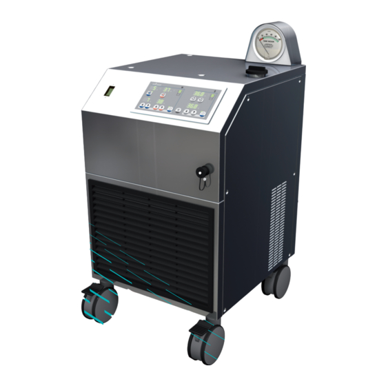
Heater-Cooler System 3T • System description Structure of the heater-cooler 3.2 Structure of the heater-cooler 3.2.1 Heater-cooler overview 9 10 CP_IFU_16-XX-XX_USA_023... - Page 26 Heater-Cooler System 3T • System description Structure of the heater-cooler Items depicted in heater-cooler overview Item Name Function Mains power switch For powering the heater-cooler on/off ● Integrated automatic circuit breaker ● Control panel For separated operation and configuration of the three circuits Two patient circuits ●...
- Page 27 Heater-Cooler System 3T • System description Structure of the heater-cooler Items depicted in heater-cooler overview (continued) Item Name Function Connection line (short line) For connecting the aerosol collection container to the heater-cooler Vacuum port (V) Connection point on the aerosol collection container for the vacuum source line Vacuum source line (long line) For connecting the aerosol collection...
- Page 28 Heater-Cooler System 3T • System description Structure of the heater-cooler 3.2.2 Heater-cooler control panel overview The control panel manages all control and monitoring functions of the heater- cooler. Specifically, the control panel: Is used to adjust the temperature set values ●...
- Page 29 Heater-Cooler System 3T • System description Structure of the heater-cooler Cardioplegia circuit controls Cold Warm ° ° ° ° ° ° Item Name Function Actual temperature display Display the actual tank temperatures Cold cardioplegia circuit Stop/Stop For starting and stopping the circuit and for switching from the warm to the cold tank button Warm cardioplegia circuit Stop/Stop...
- Page 30 Heater-Cooler System 3T • System description Structure of the heater-cooler Patient 1 and patient 2 circuit controls ° ° ° ° ° ° Item Name Function Actual temperature display Display the actual tank temperatures Patient 1 circuit Start/Stop button For starting and stopping the patient 1 circuit Patient 2 circuit Start/Stop button For starting and stopping the patient 2...
- Page 31 Heater-Cooler System 3T • System description Structure of the heater-cooler Explanation of the water level display Water level displays ° ° ° Display Segment color Water level meaning Second green Maximum capacity First green Full Orange Solid: Low level Blinking: Low level warning. Refill recommended.
- Page 32 Heater-Cooler System 3T • System description Structure of the heater-cooler Explanation of special Set value button operations ° ° ° Set value buttons For the cardioplegia Set values, pressing and holding a Set value button ● changes the temperature value by 1°C. Continuing to hold the Set value button will increase or decrease the set value more rapidly.
-
Page 33: Preparing The Heater-Cooler For A Procedure
4 Preparing the heater-cooler for a procedure Read the following chapter This chapter provides instructions for thoroughly before operating the preparing the heater-cooler for use. heater-cooler for the first time. See chapter 5 for detailed instructions for positioning and using the heater-cooler during a procedure. -
Page 34: General Technical Requirements
Heater-Cooler System 3T • Preparing the heater-cooler for a procedure General technical requirements 4.1 General technical requirements 4.1.1 General use requirements Operate the heater-cooler only at ambient temperatures between 10 °C and ● 30 °C. Operate the heater-cooler in a spacious area. The heater-cooler can overheat if ●... - Page 35 3T Aerosol Collection Set (part number 050900100) ● Important LivaNova recommends always having a replacement heater-cooler available in case the heater-cooler in use is no longer functional (e.g., due to a total system failure). The replacement heater-cooler must have compatible connectors.
-
Page 36: Conducting Any Required Disinfection And Maintenance
Heater-Cooler System 3T • Preparing the heater-cooler for a procedure Conducting any required disinfection and maintenance 4.2 Conducting any required disinfection and maintenance Before first-time use of the heater-cooler Complete the following procedures per the maintenance schedule in chapter 6.2.1 “Schedule: Disinfection and maintenance”: Disinfect the external surfaces Disinfect the water circuits... -
Page 37: Connecting The Procedural Tubing
Heater-Cooler System 3T • Preparing the heater-cooler for a procedure Connecting the procedural tubing 4.3 Connecting the procedural tubing Important Follow your hospital’s policies regarding the use of personal protective ● equipment (PPE). Before connecting any tubings to the heater-cooler: ●... - Page 38 Heater-Cooler System 3T • Preparing the heater-cooler for a procedure Connecting the procedural tubing Connect tubing to the water circuits 1 Before connecting any tubing to the heater-cooler, disinfect the following items: all heater-cooler connectors ○ all tubing fittings and connectors ○...
- Page 39 Heater-Cooler System 3T • Preparing the heater-cooler for a procedure Connecting the procedural tubing 2 Connect the procedural tubing to Circuit inlet and outlet ports the circuit inlet and outlet ports: Push and hold the quick release Quick release ring ○...
-
Page 40: Connecting The Potential Equalization Cable And The Power Supply
Heater-Cooler System 3T • Preparing the heater-cooler for a procedure Connecting the potential equalization cable and the power supply 4.4 Connecting the potential equalization cable and the power supply Summary of steps you will complete in this section Connect the potential equalization cable Connect the power cable Connect the potential equalization cable ... - Page 41 Heater-Cooler System 3T • Preparing the heater-cooler for a procedure Connecting the potential equalization cable and the power supply Connect the power cable 1 Connect the AC power cable Power cable to an appropriate outlet. WARNING Do not connect the heater-cooler to a heart-lung machine’s auxiliary outlet. The heater-cooler should be connected to a separate dedicated AC line.
-
Page 42: Connecting The Aerosol Collection Set
Heater-Cooler System 3T • Preparing the heater-cooler for a procedure Connecting the aerosol collection set 4.5 Connecting the aerosol collection set WARNING Operation of the heater-cooler without an applied vacuum source will stop the collection of aerosol from the water tanks. Summary of steps you will complete in this section Dispose of the aerosol collection set after 7 days Prepare the heater-cooler... - Page 43 Heater-Cooler System 3T • Preparing the heater-cooler for a procedure Connecting the aerosol collection set Dispose of the aerosol collection set after 7 days If an aerosol collection set is already attached to the heater-cooler (e.g., from a previous procedure), check the installation date written on the aerosol collection canister lid: If the aerosol collection set is more Installation date...
- Page 44 Heater-Cooler System 3T • Preparing the heater-cooler for a procedure Connecting the aerosol collection set Prepare the heater-cooler 1 Make sure that the heater-cooler is powered off. 2 Verify that the vacuum gauge Vacuum = 0 Pa reads 0 Pa. If the vacuum gauge does not read 0 Pa, use the provided screwdriver to turn the adjustment screw near...
- Page 45 Heater-Cooler System 3T • Preparing the heater-cooler for a procedure Connecting the aerosol collection set Prepare the aerosol collection canister 1 Gather a new aerosol collection set, and remove the components from the packaging: Aerosol collection canister ○ Canister lid ○...
- Page 46 Heater-Cooler System 3T • Preparing the heater-cooler for a procedure Connecting the aerosol collection set Connect the aerosol collection set to the heater-cooler 1 Connect the heater-cooler Heater-cooler connection line (the short line) to overflow outlet the heater-cooler overflow outlet. CAUTION Do not connect the heater-cooler connection line to the vacuum service port or the drain valve.
- Page 47 5 Connect the vacuum source line’s External vacuum source (the long line) other end to the external vacuum source. NOTE: LivaNova recommends connecting an overflow safety trap to the external vacuum source. Vacuum source line This will avoid liquid introduction into the external vacuum source’s...
- Page 48 Heater-Cooler System 3T • Preparing the heater-cooler for a procedure Connecting the aerosol collection set 6 Check that all lid caps and Top view of lid connections are secure: Vacuum source line (a) Heater-cooler connection line (b) Tandem port cap (c) Pour spout cap (d) Vacuum source extension line (if applicable)
-
Page 49: Connecting To The S5/C5 System (If Applicable)
Heater-Cooler System 3T • Preparing the heater-cooler for a procedure Connecting to the S5/C5 System (if applicable) 4.6 Connecting to the S5/C5 System (if applicable) Connect the heater-cooler to the S5/C5 System Connect the heater-cooler to the S5/C5 System according to the separate S5/C5 System’s operating instructions. -
Page 50: Filling And Mixing Water Tanks
Heater-Cooler System 3T • Preparing the heater-cooler for a procedure Filling and mixing water tanks 4.7 Filling and mixing water tanks Important Follow your hospital’s policies regarding the use of personal protective ● equipment (PPE). Do not use de-ionized or reverse osmosis processed water. These types of ●... - Page 51 Heater-Cooler System 3T • Preparing the heater-cooler for a procedure Filling and mixing water tanks Prepare for filling 1 Make sure that you have access to filtered tap water that has been filtered using the following filter and specifications: Important Disposable Pall-Aquasafe water filter with an 0.2 μm membrane (Pall part reference in the U.S.: “AQINA”;...
- Page 52 Heater-Cooler System 3T • Preparing the heater-cooler for a procedure Filling and mixing water tanks 6 Make sure that both drain valves are fully closed so that water does not flow out when filling the water tanks. 7 Press the mains power switch to power on the heater-cooler.
- Page 53 Heater-Cooler System 3T • Preparing the heater-cooler for a procedure Filling and mixing water tanks Fill the water tanks Important As you pour water into the single filler neck, all three tanks will fill in the following order: Cold cardioplegia tank ●...
- Page 54 Heater-Cooler System 3T • Preparing the heater-cooler for a procedure Filling and mixing water tanks 2 Pause filling when the orange Patient circuit segment on the patient circuit ° water level display lights up. ° 3 Pour 150 mL of medical grade 3% 150 mL hydrogen peroxide hydrogen peroxide solution into the tank.
- Page 55 Heater-Cooler System 3T • Preparing the heater-cooler for a procedure Filling and mixing water tanks Prepare for mixing 1 On the back of the heater-cooler, Close all valves make sure that the three red valve levers are closed. Turn clockwise to close.
- Page 56 Heater-Cooler System 3T • Preparing the heater-cooler for a procedure Filling and mixing water tanks Mix the tank contents 1 Press the cold cardioplegia circuit Press cold cardioplegia to start Start/Stop button to start mixing. NOTE: The green LEDs will flash alternately to indicate the circuit is running.
-
Page 57: Using The Heater-Cooler During A Procedure
5 Using the heater-cooler during a procedure Read the following chapter This chapter provides instructions for thoroughly before operating the positioning the heater-cooler in the heater-cooler for the first time. OR and using the heater-cooler’s controls during a procedure. See chapter 4 for detailed instructions for preparing the heater- cooler for use. -
Page 58: Positioning The Heater-Cooler In The Or
Heater-Cooler System 3T • Using the heater-cooler during a procedure Positioning the heater-cooler in the OR 5.1 Positioning the heater-cooler in the OR Important Do not cover the ventilation grills. ● Maintain at least 70 cm clearance from walls and other devices to prevent the ●... - Page 59 Heater-Cooler System 3T • Using the heater-cooler during a procedure Positioning the heater-cooler in the OR Place the heater-cooler in a safe position 1 Place the heater-cooler at a sufficient distance (at least 70 cm) from walls and other devices. Make sure that the ventilation grills are not covered.
- Page 60 Heater-Cooler System 3T • Using the heater-cooler during a procedure Positioning the heater-cooler in the OR 3 Step down on the brakes and lock the castors. Lock brakes Connect a portable vacuum source, if needed If you are using a portable vacuum source, mount and operate the device according to its instructions for use.
-
Page 61: Connecting The Procedural Tubing To External Devices
Heater-Cooler System 3T • Using the heater-cooler during a procedure Connecting the procedural tubing to external devices 5.2 Connecting the procedural tubing to external devices Summary of steps you will complete in this section Connect the procedural tubing to the external devices Check the procedural tubing and connections to all devices Connect the procedural tubing to the external devices ... - Page 62 Heater-Cooler System 3T • Using the heater-cooler during a procedure Connecting the procedural tubing to external devices Overview of a typical circuit Cardioplegic solution Heating/cooling blankets Cardioplegia Patient (single-use) heat exchanger Oxygenator Patient Oxygenator heat exchanger Connection patient circuit 1 Connection Connection patient circuit 2...
-
Page 63: Powering On And Checking The Panel
Heater-Cooler System 3T • Using the heater-cooler during a procedure Powering on and checking the panel 5.3 Powering on and checking the panel WARNING Operation of the heater-cooler without an applied vacuum source will stop the collection of aerosol from the water tanks. Summary of steps you will complete in this section Connect the vacuum source Power on the heater-cooler and observe the self-test... - Page 64 Heater-Cooler System 3T • Using the heater-cooler during a procedure Powering on and checking the panel 2 Check the installation date on the No more than 7 days old aerosol collection canister. If more than 7 days have passed since the installation date, dispose of the aerosol collection canister and install a new one...
- Page 65 Heater-Cooler System 3T • Using the heater-cooler during a procedure Powering on and checking the panel Power on the heater-cooler and observe the self-test 1 Press the mains power switch to power on the heater-cooler. 2 The heater-cooler will run a self-test while powering up. All of the control panel’s LEDs and 7-segment displays will illuminate for 2 seconds, and a tone will sound.
- Page 66 Heater-Cooler System 3T • Using the heater-cooler during a procedure Powering on and checking the panel Check the control panel to confirm the heater-cooler is ready for use Important Do not use the heater-cooler if the elements on the control panel are flashing. If the control panel is flashing, the heater-cooler is in service mode.
- Page 67 Heater-Cooler System 3T • Using the heater-cooler during a procedure Powering on and checking the panel If errors EE(E) appear on control panel If a circuit’s set point display flashes between “EE(E)” and a number, this is an error code: Error code E08, E19, or E23 might ●...
-
Page 68: Performing A Functional Check Prior To Operation
Heater-Cooler System 3T • Using the heater-cooler during a procedure Performing a functional check prior to operation 5.4 Performing a functional check prior to operation Important Perform the steps outlined in this chapter before every time you use the ● heater-cooler. - Page 69 Heater-Cooler System 3T • Using the heater-cooler during a procedure Performing a functional check prior to operation Check the setup Confirm the heater-cooler’s and portable vacuum source’s (if applicable) exhaust is pointed away from the operating field. WARNING Do not position the heater-cooler’s and portable vacuum source’s (if applicable) exhaust flow directed toward the operating field.
- Page 70 Heater-Cooler System 3T • Using the heater-cooler during a procedure Performing a functional check prior to operation Check when first switching power on Confirm that all LEDs and temperature displays on the control panel are illuminated. Confirm that a tone sounded. Confirm that the control panel is reflective of a functioning heater-cooler (i.e., the heater-cooler is not in service mode and does not display errors).
-
Page 71: Priming The Complete Circuit
Heater-Cooler System 3T • Using the heater-cooler during a procedure Priming the complete circuit 5.5 Priming the complete circuit Summary of steps you will complete in this section Adjust the set values as needed Place unused circuits in standby mode Prime the external circuits Adjust the set values as needed Important... - Page 72 Heater-Cooler System 3T • Using the heater-cooler during a procedure Priming the complete circuit Prime the external circuits Important Prime the circuits’ tubings and heat exchanger before using the heater-cooler. When you power on a circuit for the first time, an error code might appear ●...
- Page 73 Heater-Cooler System 3T • Using the heater-cooler during a procedure Priming the complete circuit 3 Prime the patient circuit(s) using Prime patient 1 and patient 2 circuits the associated pump(s). NOTE: Do not run a pump if there is no tubing connected. °...
-
Page 74: Using The Device Controls During A Procedure
Heater-Cooler System 3T • Using the heater-cooler during a procedure Using the device controls during a procedure 5.6 Using the device controls during a procedure 5.6.1 Checking the vacuum Checking the vacuum Adjust the external vacuum source to full Vacuum > 50 Pa open vacuum flow to check that the heater-cooler operates at vacuum levels greater than 50 Pa. - Page 75 Heater-Cooler System 3T • Using the heater-cooler during a procedure Using the device controls during a procedure 5.6.2 Opening and closing the circuit valves Important To fill the tubing and to run water through the circuits, the valves must be ●...
- Page 76 Heater-Cooler System 3T • Using the heater-cooler during a procedure Using the device controls during a procedure 5.6.3 Using the circuit controls Adjusting the set values Important The heater-cooler will begin adjusting temperatures to the set values 2 seconds after the last Set value button press. To adjust the set values: Up buttons Press the Set value up button to raise...
- Page 77 Heater-Cooler System 3T • Using the heater-cooler during a procedure Using the device controls during a procedure Operating the cardioplegia circuit How the cardioplegia circuit works: One circuit The cardioplegia circuit has two tanks: a Cold cardioplegia Warm warm tank and a cold tank. The warm cardioplegia and cold cardioplegia tanks operate using a single circuit.
- Page 78 Heater-Cooler System 3T • Using the heater-cooler during a procedure Using the device controls during a procedure Switching between cardioplegia tanks Start one cardioplegia circuit and the other will stop (warm or cold): Press the Start/Stop button of the inactive cardioplegia tank to run the circuit.
- Page 79 Heater-Cooler System 3T • Using the heater-cooler during a procedure Using the device controls during a procedure Operating the patient circuits How the patient circuits work: Patient 1 Patient 2 The patient 1 and patient 2 circuits operate using separate circuit valves and pumps.
-
Page 80: Completing A Procedure
Heater-Cooler System 3T • Using the heater-cooler during a procedure Completing a procedure 5.7 Completing a procedure WARNING Do not empty the external circuits until the patient has been discharged from the OR environment to reduce the potential of exposure to aerosol. 5.7.1 Drain and disconnect tubing Summary of steps you will complete in this section Confirm the patient is not in the room... - Page 81 Heater-Cooler System 3T • Using the heater-cooler during a procedure Completing a procedure Confirm the patient is not in the room Confirm that the patient has been discharged from the OR before conducting any further steps. Patient must NOT be in the room CP_IFU_16-XX-XX_USA_023...
- Page 82 Heater-Cooler System 3T • Using the heater-cooler during a procedure Completing a procedure Prepare the heater-cooler for draining 1 Make sure that the heater-cooler is powered on when draining. If needed, press the mains power switch to power on the heater- cooler.
- Page 83 Heater-Cooler System 3T • Using the heater-cooler during a procedure Completing a procedure 3 To prevent excess overflow, drain water from the patient circuit tank until the orange segment on the patient circuit water level display Drain patient circuit until orange segment flashes.
- Page 84 Heater-Cooler System 3T • Using the heater-cooler during a procedure Completing a procedure 2 With either cardioplegia pump Close cardioplegia valve, wait to drain running, turn the cardioplegia circuit’s red valve lever clockwise to close the valve. Allow the external water circuit volume to enter the tank before closing the next valve.
- Page 85 Heater-Cooler System 3T • Using the heater-cooler during a procedure Completing a procedure Disconnect the tubing from the external devices 1 Make sure that the circuits are Connect tubing drained before disconnecting any tubing. 2 Disconnect all procedural tubing from external devices.
- Page 86 Heater-Cooler System 3T • Using the heater-cooler during a procedure Completing a procedure 5.7.2 Emptying and/or disposing of the aerosol collection set Summary of steps you will complete in this section Empty the aerosol collection canister Dispose of and replace, or reconnect the aerosol collection set based on the date it was installed Empty the aerosol collection canister WARNING...
- Page 87 Heater-Cooler System 3T • Using the heater-cooler during a procedure Completing a procedure CAUTION Do not disconnect the vacuum source if the heater-cooler is powered on. 2 Disconnect the vacuum source line (the long line) from the vacuum regulator. Disconnect vacuum ...
- Page 88 Heater-Cooler System 3T • Using the heater-cooler during a procedure Completing a procedure 6 Uncap the pour spout on the Uncap pour spot aerosol collection canister. CAUTION Do not expose hydrophobic filter in Canister Lid to water when emptying the canister.
- Page 89 Heater-Cooler System 3T • Using the heater-cooler during a procedure Completing a procedure Dispose of and replace, or reconnect the aerosol collection set based on the date it was installed 1 Check the installation date written Installation date on the aerosol collection canister lid: If the aerosol collection set is less ○...
- Page 90 Heater-Cooler System 3T • Using the heater-cooler during a procedure Completing a procedure 5.7.3 Conducting any required maintenance according to schedule Clean and disinfect the heater-cooler surfaces after every use Clean and disinfect the heater- cooler surfaces after every use according to the instructions in chapter 6.3.
-
Page 91: Maintaining The Heater-Cooler
This applies to the increased service life. routine maintenance performed by the responsible organization as defined in IEC 60601-1 or the equivalent national standard, as well as to the preventive maintenance and safety checks performed by LivaNova representatives or competent service personnel. CP_IFU_16-XX-XX_USA_023... -
Page 92: General Maintenance Precautions
Only refrigerant systems experts are authorized to repair the cooling circuit. ● Do not service the internal components of the heater-cooler. Only LivaNova ● representatives — or other service personnel deemed qualified by LivaNova — are authorized to maintain, service, and repair internal components of the heater-cooler. - Page 93 The medical device log should be presented to authorized service personnel upon request. NOTE: LivaNova recommends documenting this information regardless of local regulations. Providing this information to LivaNova will assist with maintenance and support activities. Exposing the heater-cooler to disinfectant for longer than its intended ●...
-
Page 94: Maintenance Schedule And Checklists
Heater-Cooler System 3T • Maintaining the heater-cooler Maintenance schedule and checklists 6.2 Maintenance schedule and checklists This chapter includes a schedule of maintenance tasks and several checklists you should use to make sure that the heater-cooler is properly maintained, disinfected, and functioning. 6.2.1 Schedule: Disinfection and maintenance Timing Task... - Page 95 If 7 days or fewer have passed, check the fill level on the aerosol collection ○ set and empty it if needed, according to instructions in chapter 5.7.2. Contact LivaNova if the heater-cooler or any of its components are defective or damaged. CP_IFU_16-XX-XX_USA_023...
- Page 96 Do not use the heater-cooler if the heater-cooler does not meet all the ● conditions listed in this chapter. Contact LivaNova if the heater-cooler or any of its components are damaged or ● require service. Check the heater-cooler’s main power, potential equalization, and CAN cable ...
- Page 97 You/your organization is responsible for scheduling maintenance checks from a LivaNova service technician. Only LivaNova representatives — or other service personnel deemed qualified by LivaNova — are authorized to perform maintenance checks of the heater-cooler. Maintenance checks by LivaNova service technicians include, but are not limited...
- Page 98 Record or estimate the operating hours Where required by local regulations, record the operating hours of the heater- cooler. If local regulations do not require tracking of operating hours, LivaNova recommends estimating the operating hours. Schedule a maintenance check ...
-
Page 99: Cleaning And Disinfecting External Surfaces, Connectors, And Fittings
Heater-Cooler System 3T • Maintaining the heater-cooler Cleaning and disinfecting external surfaces, connectors, and fittings 6.3 Cleaning and disinfecting external surfaces, connectors, and fittings Cleaning and disinfecting schedule After every use, clean and disinfect the device surfaces ● Upon every connection, disinfect the tubing connectors on the heater-cooler ●... - Page 100 Heater-Cooler System 3T • Maintaining the heater-cooler Cleaning and disinfecting external surfaces, connectors, and fittings 6.3.1 Cleaning and disinfecting heater-cooler external surfaces Summary of steps you will complete in this section: Clean and disinfect the vacuum gauge Clean all accessible device surfaces Disinfect all accessible device surfaces Clean and disinfect the vacuum gauge ...
- Page 101 Heater-Cooler System 3T • Maintaining the heater-cooler Cleaning and disinfecting external surfaces, connectors, and fittings Clean all accessible device surfaces 1 Remove liquid spills (such as Clean all surfaces blood) from the device surfaces as quickly as possible. 2 Remove any surface contamination using pre-soaked disinfectant wipes.
- Page 102 Heater-Cooler System 3T • Maintaining the heater-cooler Cleaning and disinfecting external surfaces, connectors, and fittings 6.3.2 Disinfecting the tubing connectors on the heater-cooler Disinfect tubing connectors on the heater-cooler Important Make sure that no liquids enter the housing of the heater-cooler when spraying disinfectant.
- Page 103 Heater-Cooler System 3T • Maintaining the heater-cooler Cleaning and disinfecting external surfaces, connectors, and fittings 6.3.3 Disinfecting the fittings and connectors on the tubing Disinfect all connectors and fittings on the tubing 1 Conduct steps 2 through 4 on all fittings and connectors on short circuit and procedural tubing.
-
Page 104: Disinfecting The Water Circuits Every 14 Days
Heater-Cooler System 3T • Maintaining the heater-cooler Disinfecting the water circuits every 14 days 6.4 Disinfecting the water circuits every 14 days Water circuit disinfecting schedule Disinfect the water circuits every 14 days, regardless of water changes. ● Take water samples before and after disinfecting the system if you are ●... - Page 105 Do not use disinfectants in the water circuits during a surgical intervention. Only use disinfectants preoperatively and postoperatively. Important Use only LivaNova-approved disinfectants to disinfect the water circuits. The ● use of any other disinfectant is explicitly not recommended. Other...
- Page 106 Heater-Cooler System 3T • Maintaining the heater-cooler Disinfecting the water circuits every 14 days List of the approved disinfectants Product name Manufacturer EPA Reg. No. Clorox Germicidal Bleach Clorox Company 5813-100-67619 (8.25% sodium hypochlorite) Minncare Cold Sterilant Minntech Corporation 52252-4 Check the availability of the recommended disinfectants in your country, if applicable.
- Page 107 Heater-Cooler System 3T • Maintaining the heater-cooler Disinfecting the water circuits every 14 days 6.4.2 Disinfecting the water circuits Important During the disinfection procedure, leave the used 3T Aerosol Collection Set ● connected to the heater-cooler. Make sure procedural tubing is disconnected from the heater-cooler prior to ●...
- Page 108 Heater-Cooler System 3T • Maintaining the heater-cooler Disinfecting the water circuits every 14 days Prepare for the disinfection procedure 1 Press the mains power switch to power off the heater-cooler. 2 Disconnect the aerosol collection canister’s vacuum line from the external vacuum source.
- Page 109 Heater-Cooler System 3T • Maintaining the heater-cooler Disinfecting the water circuits every 14 days Drain the water tanks Important When draining the water tanks, drain the solution into buckets or directly into floor drains. 1 Twist both drain valve knobs counterclockwise until the drain valves are fully open.
- Page 110 Heater-Cooler System 3T • Maintaining the heater-cooler Disinfecting the water circuits every 14 days Prepare for filling 1 Make sure that both drain valves are fully closed so that water does not flow out when filling the water tanks. Important Make sure to completely drain the water tanks prior to filling with water and disinfectant.
- Page 111 Heater-Cooler System 3T • Maintaining the heater-cooler Disinfecting the water circuits every 14 days 4 Apply four sprays of disinfectant on the cap until all surfaces are wet, including the cap’s underside and sealing surface. All cap surfaces 5 Wait for 5 minutes. Ensure that all surfaces remain wet with Wait for 5 minutes, then wipe disinfectant during this time.
- Page 112 Heater-Cooler System 3T • Maintaining the heater-cooler Disinfecting the water circuits every 14 days 2 Pause filling when the orange Patient circuit segment on the patient circuit ° water level display lights up. ° 3 Add one disinfectant to the tank contents using the appropriate amount: WARNING Use only one disinfectant.
- Page 113 Heater-Cooler System 3T • Maintaining the heater-cooler Disinfecting the water circuits every 14 days 4 Continue filling the tanks with Patient circuit filtered tap water until the second ° green segment of the patient circuit water level display lights °...
- Page 114 Heater-Cooler System 3T • Maintaining the heater-cooler Disinfecting the water circuits every 14 days 3 Connect the short-circuit tubing Patient 1 Cardioplegia between the cardioplegia circuit inlet and the patient 1 circuit inlet. 4 To avoid triggering a high temperature warning while mixing: Set the cold cardioplegia Set the...
- Page 115 Heater-Cooler System 3T • Maintaining the heater-cooler Disinfecting the water circuits every 14 days Mix the tank contents 1 Press the cold cardioplegia circuit Press cold cardioplegia to start Start/Stop button to start mixing. NOTE: The green LEDs will flash alternately to indicate the circuit is running.
- Page 116 Heater-Cooler System 3T • Maintaining the heater-cooler Disinfecting the water circuits every 14 days Prepare to run the disinfectant solution through the system Important All circuits, including those not used during procedures, must be connected to tubing in order to disinfect the system: Make sure to connect procedural tubing to any circuits that are used during ●...
- Page 117 Heater-Cooler System 3T • Maintaining the heater-cooler Disinfecting the water circuits every 14 days 3 Connect the procedural tubing Connect tubing between the circuits using the suitable short-circuit connectors: Cardioplegia circuit’s inlet and ○ outlet Patient 1 circuit’s inlet and outlet ○...
- Page 118 Heater-Cooler System 3T • Maintaining the heater-cooler Disinfecting the water circuits every 14 days Run the disinfectant solution through the system 1 Start running the circuit pumps: Press the warm cardioplegia circuit Press the patient 1 and patient 2 Start/Stop button.
- Page 119 Heater-Cooler System 3T • Maintaining the heater-cooler Disinfecting the water circuits every 14 days 3 After 10 minutes, turn the three Close valves red valve levers clockwise to close the valves. Allow the circuit pumps to run until the tubing is drained. CAUTION Running the circuit pumps with disinfectant solution for more than 11 minutes might damage the heater- cooler.
- Page 120 Heater-Cooler System 3T • Maintaining the heater-cooler Disinfecting the water circuits every 14 days Drain the disinfectant from the water tanks Important When draining the water tanks, drain the solution into buckets or directly into floor drains. 1 Twist both drain valve knobs counterclockwise until the drain valves are fully open.
- Page 121 Heater-Cooler System 3T • Maintaining the heater-cooler Disinfecting the water circuits every 14 days Rinse the tanks and tubing two (2) times CAUTION To remove residual disinfectant solution from the system, rinse the tanks and tubing after every disinfection cycle two (2) times as described below. ...
- Page 122 Heater-Cooler System 3T • Maintaining the heater-cooler Disinfecting the water circuits every 14 days 4 Start running the circuit pumps: Press warm Press patient 1, cardioplegia patient 2 Press the warm cardioplegia ○ circuit Start/Stop button Press the patient 1 and patient 2 ○...
- Page 123 Heater-Cooler System 3T • Maintaining the heater-cooler Disinfecting the water circuits every 14 days Important When draining the water tanks, drain the solution into buckets or directly into floor drains. 7 Twist both drain valve knobs counterclockwise until the drain valves are fully open.
- Page 124 Heater-Cooler System 3T • Maintaining the heater-cooler Disinfecting the water circuits every 14 days Replace the aerosol collection set Replace the aerosol collection set according to chapter 5.7.2. The disinfection procedure is now complete. The heater-cooler may now be prepared for a procedure (see chapter 4) or placed in storage (see chapter 6.7).
-
Page 125: Monitoring The Tank Water
Heater-Cooler System 3T • Maintaining the heater-cooler Monitoring the tank water 6.5 Monitoring the tank water 6.5.1 Monitoring the hydrogen peroxide concentration daily Hydrogen peroxide monitoring schedule Check hydrogen peroxide concentration daily, before heater-cooler use. ● Check daily, even if the heater-cooler is not in use. ●... - Page 126 Heater-Cooler System 3T • Maintaining the heater-cooler Monitoring the tank water Summary of steps you will complete in this section: Collect a sample Interpret the hydrogen peroxide concentration Take action based on the hydrogen peroxide concentration Make sure the water tanks are full CP_IFU_16-XX-XX_USA_023...
- Page 127 Heater-Cooler System 3T • Maintaining the heater-cooler Monitoring the tank water Collect a sample 1 Twist the patient circuit drain valve knob counterclockwise to open the patient circuit drain valve. 2 Drain at least 100 mL of solution from the drain valve and discard.
- Page 128 Heater-Cooler System 3T • Maintaining the heater-cooler Monitoring the tank water Interpret the hydrogen peroxide concentration 1 Immerse the test strip in the sample container for the time specified in the test strip Test strip instructions. 2 Then, remove the strip and shake any excess liquid from the test Shake off strip.
- Page 129 Heater-Cooler System 3T • Maintaining the heater-cooler Monitoring the tank water Take action based on the hydrogen peroxide concentration Acceptable concentration: greater than or equal to 100 mg/L H There is no additional action to be taken other than to monitor the concentration daily.
- Page 130 Heater-Cooler System 3T • Maintaining the heater-cooler Monitoring the tank water (Continued) Unacceptable concentration: less than 100 mg/L H 4 Wait for 5 minutes. Ensure that all surfaces remain wet with Wait for 5 minutes, then wipe disinfectant during this time. off excess for 2 minutes Apply additional disinfectant if necessary.
- Page 131 Heater-Cooler System 3T • Maintaining the heater-cooler Monitoring the tank water Make sure the water tanks are full Important Do not add volume to the tanks until you complete the hydrogen peroxide test and adjustment procedures. 1 Determine if the water tank Acceptable volume volume is acceptable by checking Cardioplegia or patient circuits...
- Page 132 Heater-Cooler System 3T • Maintaining the heater-cooler Monitoring the tank water 6.5.2 Monitoring the water for bacteria and NTM Bacteria and NTM monitoring schedule At least once a month, monitor the tanks’ water for bacteria and NTM. ● When you monitor the tanks for bacteria and NTM, do so when you are ●...
- Page 133 Heater-Cooler System 3T • Maintaining the heater-cooler Monitoring the tank water Prepare to collect a water sample 1 Label the samples with the serial Serial number location number or internal identification number of the heater-cooler based on your hospital’s policies. Label with serial number ...
- Page 134 Heater-Cooler System 3T • Maintaining the heater-cooler Monitoring the tank water 4 Disinfect the procedural tubing connectors and a suitable short-circuit connector (part number 73-300-160). Important Disinfect the connectors and fittings every time you make a connection according to chapter 6.3.2 and chapter 6.3.3. ...
- Page 135 Heater-Cooler System 3T • Maintaining the heater-cooler Monitoring the tank water 7 If the heater-cooler is powered off, press the mains power switch to power on the heater-cooler. 8 Start running the circuit pumps: Press warm Press patient 1, cardioplegia patient 2 Press the...
- Page 136 Heater-Cooler System 3T • Maintaining the heater-cooler Monitoring the tank water Collect the sample 1 Check to make sure the disinfectant is completely dry. Do Make sure valve is dry not take water samples until the disinfectant has completely dried. Important When draining the water tank, drain the solution into buckets or directly into floor drains.
- Page 137 Heater-Cooler System 3T • Maintaining the heater-cooler Monitoring the tank water 5 Before closing the drain valve, fill each sample container needed for the test you are running. Bacteria check, every month: ○ Fill one 50 mL container. NTM check, every month: ○...
- Page 138 Contact your hygiene officer and your authorized service technician. LivaNova can provide an optional Deep Cleaning service for the system. Please contact your service technician or sales representative to request this service.
- Page 139 Contact your hygiene officer and your authorized service technician. LivaNova can provide an optional Deep Cleaning service for the system. Please contact your service technician or sales representative to request this service.
-
Page 140: Changing The Water And Adding Hydrogen Peroxide
Heater-Cooler System 3T • Maintaining the heater-cooler Changing the water and adding hydrogen peroxide 6.6 Changing the water and adding hydrogen peroxide Water change schedule: At least once a week ● Important Follow your hospital’s policies regarding the use of personal protective ●... - Page 141 Heater-Cooler System 3T • Maintaining the heater-cooler Changing the water and adding hydrogen peroxide Drain the water tanks Important When draining the water tanks, drain the solution into buckets or directly into floor drains. 1 Twist both drain valve knobs counterclockwise until the drain valves are fully open.
- Page 142 Heater-Cooler System 3T • Maintaining the heater-cooler Changing the water and adding hydrogen peroxide 2 Make sure that both drain valves are fully closed so that water does not flow out when filling the water tanks. 3 Press the mains power switch to power on the heater-cooler.
- Page 143 Heater-Cooler System 3T • Maintaining the heater-cooler Changing the water and adding hydrogen peroxide Fill the water tanks Important As you pour water into the single filler neck, all three tanks will fill in the following order: Cold cardioplegia tank ●...
- Page 144 Heater-Cooler System 3T • Maintaining the heater-cooler Changing the water and adding hydrogen peroxide 4 Continue filling the tanks with Patient circuit filtered tap water until the second ° green segment of the patient circuit water level display lights °...
- Page 145 Heater-Cooler System 3T • Maintaining the heater-cooler Changing the water and adding hydrogen peroxide 2 Apply four sprays of disinfectant on the short-circuit tubing’s male connectors until all surfaces are wet. 3 Wait for 5 minutes. Ensure that all surfaces remain wet with disinfectant during this time.
- Page 146 Heater-Cooler System 3T • Maintaining the heater-cooler Changing the water and adding hydrogen peroxide 7 Connect the short-circuit tubing Patient 1 Cardioplegia between the cardioplegia circuit inlet and the patient 1 circuit inlet. 8 To avoid triggering a high temperature warning while mixing: Set the cold cardioplegia Set the...
- Page 147 Heater-Cooler System 3T • Maintaining the heater-cooler Changing the water and adding hydrogen peroxide 2 After 5 minutes, press the cold After 5 minutes, press to stop cardioplegia circuit Start/Stop button again to stop mixing. ° ° 3 Disconnect the short-circuit tubing between the cardioplegia circuit inlet and the patient 1 circuit inlet.
-
Page 148: Preparing The Heater-Cooler For Storage
Heater-Cooler System 3T • Maintaining the heater-cooler Preparing the heater-cooler for storage 6.7 Preparing the heater-cooler for storage Important Disinfect the heater-cooler every 14 days during storage. Summary of steps you will complete in this section: Clean and disinfect the entire system Make sure all tanks are drained Disconnect and store all tubings Clean and disinfect the entire system... - Page 149 Heater-Cooler System 3T • Maintaining the heater-cooler Preparing the heater-cooler for storage Make sure all tanks are drained Important When draining the water tanks, drain the solution into buckets or directly into floor drains. 1 Twist both drain valve knobs counterclockwise until the drain valves are fully open.
-
Page 150: Cleaning The Heater-Cooler Interior
Heater-Cooler System 3T • Maintaining the heater-cooler Cleaning the heater-cooler interior 6.8 Cleaning the heater-cooler interior Important Clean the interior of your heater-cooler regularly or if the fan behind the front ventilation grill is running too quickly and/or too loudly. Cleaning the interior of the heater-cooler will eliminate any dust that has collected inside the heater- cooler and has inhibited air circulation. - Page 151 Heater-Cooler System 3T • Maintaining the heater-cooler Cleaning the heater-cooler interior Disconnect from the power supply Disconnect the heater-cooler’s power cable from the power supply outlet. Clean the accessible areas behind the front grill 1 Unscrew the four screws on the front ventilation grill.
-
Page 152: Replacing The Tubings Once A Year
Heater-Cooler System 3T • Maintaining the heater-cooler Replacing the tubings once a year 6.9 Replacing the tubings once a year Replace the procedural tubing at least once a year Use only tubing that is approved for use with the heater-cooler (i.e. part number 75-510-218). -
Page 153: Technical Specifications
7 Technical specifications This chapter provides technical specifications including information about the heater-cooler’s physical characteristics, labeling, part numbers, accessories, and electromagnetic compatibility. This chapter also includes warranty information. CP_IFU_16-XX-XX_USA_023... -
Page 154: Specifications
Heater-Cooler System 3T • Technical specifications Specifications 7.1 Specifications 7.1.1 Dimensions and weights Heater-cooler Width 500 mm Height 975 mm Depth 680 mm Weight (when empty) 100 kg Max. weight of equipped device 125 kg 7.1.2 Operating, storage and transport conditions Operating conditions Operating temperature 10 °C through 30 °C... - Page 155 Heater-Cooler System 3T • Technical specifications Specifications 7.1.3 Electrical specifications Heater-cooler Drip-proof IPX1 Input current 16 A 13 A for devices with a BS 1363 (type G) mains plug Input voltage (variants Mains Voltage, Mains Frequency, Maximum Current are device-specific) Nominal (V) Nominal (Hz) Draw (A)
- Page 156 Heater-Cooler System 3T • Technical specifications Specifications 7.1.4 General performance data General data Heating element performance 3 x 650 W (input voltage 120/127 V ~) (2 x patient, 1 x cardioplegia) 3 x 900 W (input voltage 200 V ~) 3 x 1,000 W (input voltage 200/208 V ~) 3 x 1,150 W (input voltage 220 V ~) 3 x 1,250 W (input voltage 230 V ~)
- Page 157 Heater-Cooler System 3T • Technical specifications Specifications Cleaning and disinfection process Disinfection Effectiveness Devices were inoculated with at least Test devices achieved the following CFU/ml or greater levels of results: organisms prior to executing the P. aeruginosa: 99.9999% reduction ● disinfection process described in chapter 6.4 of the operating M.
- Page 158 Heater-Cooler System 3T • Technical specifications Specifications Aerosol collection set effectiveness Physical Assay Devices with the Aerosol Collection Aerosol Collection Sets reduced particle Set were studied using aerosol emission in excess of 99.0% during the particle sizing (APS) methodology to water warming phase and water circuit determine the effectiveness of the valve closure phase in the following tests:...
- Page 159 Heater-Cooler System 3T • Technical specifications Specifications 7.1.5 Information about global warming potentials The cooling circuit of the heater-cooler is filled with a CFC-free HFC- (hydrofluorocarbons) refrigerant. Refer to the device label and chapter 7.2 for further information about the type and volume of the refrigerant. Global warming potentials Refrigerant R-134/HFC-134a...
-
Page 160: Icons And Labels
Heater-Cooler System 3T • Technical specifications Icons and labels 7.2 Icons and labels 7.2.1 Icons and designations on the nameplates Regulatory symbols and quality marks This device complies with the requirements of EU Directive 93/42/EEC of the European Council for Medical Devices. 0123 Only applies in the U.S.A. - Page 161 Heater-Cooler System 3T • Technical specifications Icons and labels Additional icons and designations Purchase order number Serial number Date of manufacture Manufacturer Unique Device Identifier (UDI) 125 kg Maximum permitted load: A primed and filled heater-cooler must not exceed a total weight of 125 kg.
- Page 162 Heater-Cooler System 3T • Technical specifications Icons and labels 7.2.2 Icons and additional labels on the housing Follow instructions for use General warning sign Potential equalization point Outlets and inlets of the patient circuits and cardioplegia circuit Drain valve of the patient circuits Drain valve of the cardioplegia circuit This cooling system contains fluorinated This cooling system contains fluorinated...
- Page 163 Heater-Cooler System 3T • Technical specifications Icons and labels 7.2.3 Icons on the packaging Fragile item Packaged item is extremely sensitive. Handle with care. This side up Always keep in upright position. Keep dry Keep out of precipitation. Temperature limitation Transport and store within the permissible temperature range.
-
Page 164: Part Numbers
Part numbers 7.3 Part numbers Refer to chapter 6 in these operating instructions for the cleaning and disinfection instructions of reusable products manufactured by LivaNova. Additionally, refer to chapter 6 for disposal instructions for disposables products manufactured by LivaNova. For other products that are delivered with separate instructions for use, refer to the manufacturer’s instructions on the cleaning and disinfection of reusable... - Page 165 Heater-Cooler System 3T • Technical specifications Part numbers Other parts Part name Part number Manufacturer Use type Tubing connector ½", 90° angle 16-10-17* LivaNova Reusable Tubing connector ½", straight 73-300-019* LivaNova Reusable Water tubing ½", blue (25 m) 75-510-218* LivaNova Reusable Hansen coupling ⅜"...
-
Page 166: Tested Accessories
7.4 Tested accessories Compatibility of the Heater-Cooler System 3T with the products listed in the table below has been tested by LivaNova Deutschland GmbH and is thus guaranteed. The products listed below must be used in compliance with the separate instructions for use provided by the manufacturer. -
Page 167: Information On Electromagnetic Compatibility (Emc)
Heater-Cooler System 3T • Technical specifications Information on electromagnetic compatibility (EMC) according to IEC 60601-1-2 (4th edition) 7.6 Information on electromagnetic compatibility (EMC) according to IEC 60601-1-2 (4th edition) 7.6.1 Guidance and manufacturer’s declaration Medical electrical equipment needs precautions regarding electromagnetic compatibility and has to be installed and put into service according to the EMC information provided in the following guidance and the manufacturer’s declaration. - Page 168 Heater-Cooler System 3T • Technical specifications Information on electromagnetic compatibility (EMC) according to IEC 60601-1-2 (4th edition) Guidance and manufacturer’s declaration – electromagnetic emission The Heater-Cooler System 3T is intended for use in the professional healthcare facility environment specified below. In order to prevent adverse advents to the patient and operator due to electromagnetic disturbances, the Heater-Cooler System 3T must not be operated outside its intended EMC environment.
- Page 169 Heater-Cooler System 3T • Technical specifications Information on electromagnetic compatibility (EMC) according to IEC 60601-1-2 (4th edition) Guidance and manufacturer’s declaration – electromagnetic immunity The Heater-Cooler System 3T is intended for use in the professional healthcare facility environment specified below. In order to prevent adverse advents to the patient and operator due to electromagnetic disturbances, the Heater-Cooler System 3T must not be operated outside its intended EMC environment.
- Page 170 Heater-Cooler System 3T • Technical specifications Information on electromagnetic compatibility (EMC) according to IEC 60601-1-2 (4th edition) Test specifications for enclosure port immunity to RF wireless communications equipment Test Band (MHz) Service Modulation Maximum Distance Immunity frequency power (W) test level (MHz) (V/m) 380–390...
- Page 171 Heater-Cooler System 3T • Technical specifications Information on electromagnetic compatibility (EMC) according to IEC 60601-1-2 (4th edition) Note: If necessary to achieve the immunity test level, the distance between the transmitting antenna and the Heater-Cooler System 3T may be reduced to 1 m. The 1 m test distance is permitted by IEC 61000-4-3.
- Page 172 Heater-Cooler System 3T • Technical specifications Information on electromagnetic compatibility (EMC) according to IEC 60601-1-2 (4th edition) Table 5: Patient coupling port Phenomenon Basic EMC standard Immunity test levels Professional healthcare facility environment Electrostatic discharge IEC 61000-4-2 ± 8 kV contact ±2 kV, ±4 kV, ±8 kV, ±...
- Page 173 Heater-Cooler System 3T • Technical specifications Information on electromagnetic compatibility (EMC) according to IEC 60601-1-2 (4th edition) The emissions limits, IEC 60601 test levels and tests specified by this collateral standard do not address electromagnetic compatibility of electrical equipment at very close distances.
- Page 174 Heater-Cooler System 3T • Technical specifications Information on electromagnetic compatibility (EMC) according to IEC 60601-1-2 (4th edition) 7.6.2 Technical description Note: The use of cables other than those specified below may result in increased emissions or decreased immunity of the heater-cooler and/or the heart-lung machine.
-
Page 175: Troubleshooting
8 Troubleshooting This chapter provides troubleshooting for warnings and error codes you might see on the control panel, and troubleshooting related to the aerosol collection set. CP_IFU_16-XX-XX_USA_023... -
Page 176: Control Panel Warnings And Error Code Displays
Power off the heater-cooler and power it on again to exit service mode. NOTE: LivaNova recommends documenting all maintenance procedures and any operating failures in a medical device log regardless of local regulations. Provide this information to LivaNova when they perform service activities. CP_IFU_16-XX-XX_USA_023... - Page 177 Heater-Cooler System 3T • Troubleshooting Control panel warnings and error code displays 8.1.1 General errors Display Possible cause(s) Effects Corrective measures Display is dark Defective fuse D 31 Affected circuit Have the heater- ● (F3) cannot be operated cooler checked by your service Defective mains ●...
- Page 178 Heater-Cooler System 3T • Troubleshooting Control panel warnings and error code displays 8.1.2 Low water level display NOTE: Refilling the water tanks to maximum water level will have a brief influence upon the actual temperature of all circuits (dependent on the temperature of the refilled water).
- Page 179 Heater-Cooler System 3T • Troubleshooting Control panel warnings and error code displays 8.1.3 High temperature display Display Possible cause(s) Effects Corrective measures The symbol of the Maximum The pumps of the You can keep the water corresponding deviations corresponding circuit running (if patient circuit lights between the circuit stop.
- Page 180 Heater-Cooler System 3T • Troubleshooting Control panel warnings and error code displays 8.1.4 Error code displays An error code consists of a series of the capital letter “E” followed by a two-digit number. An error code is usually displayed in the Set Temperatures display of the circuit in which the error has occurred and will stop the function of that circuit.
- Page 181 If the error code is cleared, you may complete the current procedure, but ● LivaNova strongly recommends the heater-cooler be taken out of service and checked by an authorized service technician as soon as possible. If the error code persists, there is a defect and the heater-cooler should not be ●...
- Page 182 Heater-Cooler System 3T • Troubleshooting Control panel warnings and error code displays Display Description of error cause Pump (stirring mechanism) is blocked. The affected component will vary depending on which display presents the error: Patient tank display: stirring mechanism ● Cold cardioplegia display: cold cardioplegia pump ●...
- Page 183 Heater-Cooler System 3T • Troubleshooting Control panel warnings and error code displays Display Description of error cause Cooler: defective fan cooler or defective rpm sensor (= Hall sensor) Fan: defective motor ● Symptoms: Fan is not running or is too slow; fan voltage ≥ mains voltage Hardware activation: error (e.g.
- Page 184 Heater-Cooler System 3T • Troubleshooting Control panel warnings and error code displays Display Description of error cause Start test (warm cardioplegia): Triac does not open Start test (warm cardioplegia): Relay or Triac does not close ● Start test for warm cardioplegia heating interrupted ●...
-
Page 185: Troubleshooting Or Returning The 3T Aerosol Collection Set
Secure filler neck cap ● removed or loose Check filler neck and cap sealing ● surfaces for debris Contact LivaNova for a replacement cap ● Circuit tanks are empty Fill tanks and recheck vacuum ● (allowing air to enter Connect procedural tubing and recheck ●... - Page 186 6 Apply air pressure through the service port using a 30 cc or larger sterile syringe 7 Replace service port cap Vacuum gauge failure Contact your LivaNova service technician Vacuum drops below Overflow safety trap Empty the overflow safety trap 50 Pa during the (“water trap”) in the...
- Page 187 Returned CV Products 14401 West 65th Way Arvada, CO 80004-3599 Instructions for cleaning and materials, including appropriate shipping containers, proper labeling, and an RGA number may be obtained from the LivaNova USA, Inc. Returned Goods Coordinator, Quality Assurance Department (phone: 800-650-2623). CP_IFU_16-XX-XX_USA_023...
- Page 188 Heater-Cooler System 3T • Troubleshooting Troubleshooting or returning the 3T Aerosol Collection Set For customers outside the United States: Contact your sales representative for specific instructions. Clean and disinfect the aerosol collection container if it has been in contact with blood or body fluids.
Need help?
Do you have a question about the 3T Heater-Cooler System and is the answer not in the manual?
Questions and answers