Table of Contents
Advertisement
Quick Links
Advertisement
Table of Contents

Summary of Contents for RefPlus Guardian+ RC-S
- Page 1 PROGRAMMING MANUAL SMART EVAPORATOR CONTROL RC-S...
-
Page 3: Table Of Contents
able of onTenTs SPECIFICATI0NS ..................................3 ACCESSORIES ..................................... 4 DIMENSIONS ....................................5 COIL SENSOR LOCATION ................................5 NAVIGATION USING THE BASIC (REMOTE) DISPLAY ......................6 MENUS AND PARAMETERS BASIC SETPOINTS MENU ..............................7 ADVANCED SETPOINTS MENU ............................7 TYPES OF CONTROL - FIRST TIME SETUP MENU ......................9 SYSTEM MODES ................................ -
Page 4: Accessories
CCessories Remote Displays Part # Description 21232 Basic (Remote) Display w/ 15 ft. cable 21324 Snap track - 12” (305 mm) 21320 Combo Display (no accessories included) 21786 Combo Display - 25 ft. Cable (762 cm) 21320 Combo Display - Junction Box 21781 9V Rechargeable Battery for Combo Display Temperature Sensors... -
Page 5: Dimensions
After the sensors are mounted, they are routed back to the controller. If the wires must be extended,use 18 gauge twisted shielded pair. Maximum, combined length, for extension: 100 ft. Contact RefPlus Therm if planning to extend sensor wires beyond 100 ft. -
Page 6: Navigation Using The Basic (Remote) Display
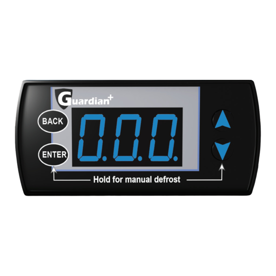
avigaTion sing The asiC emoTe isplay Basic (Remote) Display User Interface Changing Setpoints Most Guardian+ controllers ship with the Basic Display. The Pressing and holding the button will enter the Basic ENTER display allows service technicians to change the major setpoints. Setpoints menu. -
Page 7: Menus And Parameters Basic Setpoints Menu
& p enus arameTers... - Page 8 & p enus arameTers...
-
Page 9: Types Of Control - First Time Setup Menu
& p enus arameTers... -
Page 10: Alarm Status Menu
& p enus arameTers... - Page 11 & p enus arameTers...
- Page 12 & p enus arameTers...
-
Page 13: Introduction To Smart Access
Please refer to the Replacement Parts Catalogue available online at www.refplus.com (https://refplus.com/en/parts-services/) All RefPlus products have a nameplate with a QR code that you can scan to obtain the unit’s technical pedigree as well as a list of replacement parts. -
Page 14: Wiring Diagram - Powered By External Source (Pilot Duty)
iring iagram oWereD by xTernal ourCe iloT USE COPPER CONDUCTOR ONLY KE404 GUARDIAN 1 L2/N LIQUID LINE SOLENOID/ COMP CONTACTOR RELAY FAN RELAY R212 DEFROST RELAY COMPRESSOR RELAY AUX2 AUX3 TSUCT LEGEND - - - - : BY OTHERS □ TAIR TERMINAL BLOCK RSV - HSV... -
Page 15: Wiring Diagram - Powered By Condensing Unit (Line Duty)
iring iagram oWereD by onDensing 240/1/60 FROM COND. UNIT USE COPPER CONDUCTOR ONLY KE2 GUARDIAN L2/N LIQUID LINE SOLENOID/ COMP CONTACTOR RELAY BLACK RELAY WHITE DEFROST RELAY AUX2 BLACK GREEN AUX3 TSUCT LEGEND - - - - : BY OTHERS □... - Page 16 CERTIFIED ISO-9001 IOM_GUARDIAN+ RC-S CONTROLLER_EN-R4 RefPlus Inc. reserves the right to make any changes in the design or specifications of any product at any time without notice. USA & CANADA 1-888-816-2665 / refplus.com © Copyright 2023 by RefPlus Inc.
Need help?
Do you have a question about the Guardian+ RC-S and is the answer not in the manual?
Questions and answers