Table of Contents
Advertisement
Quick Links
Advertisement
Table of Contents

Related Manuals for BLACK NOISE COSMOS

Summary of Contents for BLACK NOISE COSMOS
- Page 1 COSMOS User Manual V1.0...
- Page 2 Thank you for purchasing the Cosmos. Waranty Cosmos is a new kind of module that will help you to BLACK NOISE warrants is products to be free of creating complex modulation, sounds, patterns with ease defects in materials or workmanship and to be and will lead you to new sounds territories.
-
Page 3: Table Of Contents
Envelope combiner Looking through the Cosmos . . . . . . . . . . . . . . . . . -
Page 4: Starting The Cosmos
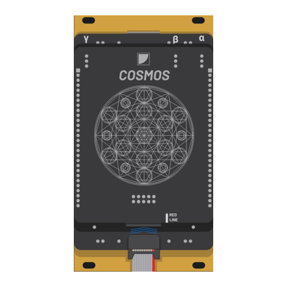
Cosmos, making sure the red stripe matches the one indicated on the bus. Place the Cosmos on the rails of your system and attach it with the included screws. Put your system’s power cord back in and turn it Test the module by pushing firmly on the tactile pads. - Page 5 Starting the Cosmos Calibration monitor This step is only in case of unexpected behavior. The module comes fully calibrated and ready to use. As the circuit is analog, some adjustment might be required over time. The trimmers on the top of the back are adjusting the threshold of their respective outputs to be converted into gates.
-
Page 6: A Map Of The Cosmos
A map of the Cosmos XOR gate XOR trig TZ CLIPPER Cheat sheet OR gate AND gate input analog out inverted analog out gate out NOT gate out OR trig AND trig X IN Y IN diff NOR trig NAND trig... -
Page 7: Looking Through The Cosmos
Looking through the Cosmos The Cosmos is large, but its structure is simple: Two inputs with normalized touch pads A top hemisphere that provides all kind of CV combination, with their logic gates and rising edge trigger counterparts A lower hemisphere that provides a phase-inverted version of the top hemisphere, with their NOT gates logic and fall trigger counterparts. -
Page 8: Entering The Cosmos
Entering the Cosmos The Cosmos has two inputs: X and Y. They can process any eurorack signal. Fixed or controlled voltage; positive, negative or bipolar signals; triggers, gates or audio signal. - Page 9 Entering the Cosmos When an input is not connected, it is replaced by the corresponding pad on the faceplate, providing a performance oriented voltage depending on the surface of skin in contact with the pad.
-
Page 10: Exploring The Cosmos
Exploring the Cosmos 1:1 buffered copy of the corresponding signal Phase-inverted copy of the corresponding signal phase inv. - Page 11 Exploring the Cosmos ( X + Y ) X and Y signal’s value are added together and then averaged fixed voltage cv - audio X IN Y IN ( X - Y ) X signal value is added to an inverted version of Y...
- Page 12 Exploring the Cosmos The Cosmos has 6 processing analog outputs: The top hemisphere’s analog outputs provide an analog processing of the two input signals A phase-inverted version is mirrored in the lower hemisphere. phase inv.
- Page 13 Exploring the Cosmos A gate output going high whenever the CV output is above 0V A trigger output firing on the rising edge of the gate high when cv > 0 volts triggers when cv passes through 0 volts...
- Page 14 Exploring the Cosmos This allows a complete set of features: All gate outputs are the binary logic version of the analog processing. Any gate output has its NOT version in the mirrored hemisphere gate output logic gate...
- Page 15 Exploring the Cosmos Any gate output finds the corresponding trigger output acting as its rising edge detector, while the mirrored trigger output acts as its falling edge detector rising edge trig falling edge trig...
- Page 16 Exploring the Cosmos Max - OR: highest value of the two signals fixed voltage cv - audio gates A fixed voltage sets the lowest value for the other signal Two waveforms combine themselves with one another Gate is high when any input is high (OR logic).
- Page 17 Exploring the Cosmos Though-zero clipper - XOR: a positive input inverts the other one and keeps the value closer to zero, producing a unique “analog XOR”, somewhere in between bipolar clipping and ring modulation. neg. voltage pos. voltage cv - audio...
- Page 18 Exploring the Cosmos The gates outputs are high when their corresponding analog output is above zero. Consequently, they cover all classic binary logic functions. INPUT INPUT X IN Y IN NAND XNOR...
-
Page 19: Controlling The Cosmos
This is why the Cosmos comes with an extensive and growing patch library for audio processing or generation, ad for CV and gate applications. -
Page 20: Half-Wave Rectifier
CV control In this patch uses analog logic to exclude or isolate Patch a signal into any input of the COSMOS, the MAX The source signal can be sent though an offset negative CV. -
Page 21: Full-Wave Rectifier
CV control In this patch uses analog logic to reflect all negative Patch a signal into any input of the COSMOS and patch The source signal can be sent though an offset values in the positive domain. Consequently a a full- the corresponding inverted output to the second input. -
Page 22: Comparator
The OR gate output channel unpatched, the knob can be used as a variable device CV controllable. of COSMOS works as an “over zero” comparator, so threshold. the original signal has to be offset by the opposite of the desired threshold beforehand. -
Page 23: Window Comparator
When setting the width (B) very low, this patch can minimum and maximum value. This window is defined by the X input of the COSMOS. This offset sets the opposite be used to an “equal” comparator, getting a high gate its center and its width. -
Page 24: Clamping Vca
Clamping VCA VCA with wave shaping for audio and CV This patch turns the COSMOS into a VCA with character. Patch a signal to the X input. Patch a modulation source The modulation signal can be sent through an offset While the VCA is transparent at max level, a lower level such as an envelope into the Y input. -
Page 25: Clamping Ring Modulation
This patch takes advantage of the TZ clipper circuit of Patch each VCO to the input of COSMOS. The TZ inv The TZ inv gate output provides a digital ring COSMOS with waveforms clamping and inverting each output provides a rich clamping ring modulation effect. -
Page 26: Complex Ring Modulation
Unlike classic ring modulation, attenuating the source modulation system for more control over the harmonic GOMA and then into COSMOS. The TZ inv output provides signals affects the harmonic content of the sound. content. The frequency of one VCO can take the high a rich clamping ring modulation effect. -
Page 27: Oscillator
- lpf Oscillator self patched squarewave CV controled oscillator Cosmos can self-oscillate by feeding its own XNOR gate Insert a slew or a filter feedback in the feedback path to The slew time will define the pitch of the oscillator. -
Page 28: Triangle Or Saw To Variable Pulse Width
Patch triangle or saw wave VCO trough an offset generator Patching a CV signal to GOMA’s 2nd input makes the width modulation to a simple VCO. and then into any input of COSMOS. This offset defines the device CV controllable. amount of signal that triggers the “over zero” comparator... -
Page 29: Saw Wave To Triangle Wave
Using COSMOS as a full-wave rectifier can turn a saw Patch a bipolar saw wave into the X input of the COSMOS The source signal can be sent through an offset wave into a triangle wave or anything in between like the and patch the corresponding inverted output to the Y input. -
Page 30: Triangle Wave To + 1 Oct Vco
The source signal can be sent though an offset VCO into a copy playing one octave higher. A square COSMOS and patch the corresponding inverted output to generator from -5 to +5V such as a GOMA, providing wave VCO can also be obtained and then mixed back the Y input. -
Page 31: Harmonic Wave Shaper
This patch uses the self-oscillating capabilities of the Patch an oscillator into the X input of Cosmos, patch the The Rise parameter sets the smoothness of the COSMOS to add harmonics to a simple oscillator, with TZ clipper gate output thought a Slew LFO, add a negative harmonics. -
Page 32: Phase Locked Loop: Vco Tracking
Patch the main VCO (controlled by a keyboard or a Fine-tuning the slew offers several timbre options. The for dubbing an oscillator with any oscillating device sequencer) and the dubbing VCO into the COSMOS. Send slew parameter can also be modulated. (VCO, audio-rate ran LFO) with perfect pitch tracking the Inv. -
Page 33: Phase Locked Loop: Looping Envelope
looping env. - vco slew - lpf offset mult mixer V/OCT Phase locked loop: looping envelope vco tracking with an audio rate looping envelope In this patch uses the previous PPL tracking concept The patch is very similar to the phase locked loop: VCO The Inv. -
Page 34: Phase Locked Loop: External Tracking
env. follower slew - lpf offset VOLTAGE PROCESSOR OFFSET OFFSET OFFSET GAIN GAIN GAIN INPUT INPUT INPUT V/OCT CURVE CURVE CURVE CV L CV L OUT L OUT L CV R IN L IN L OUT R IN R Phase locked loop: external tracking pitch tracking an external audio source In this patch uses the previous PPL concept for tracking The patch is very similar to the phase locked loop: VCO... -
Page 35: Envelope To Lfo
This patch loops an envelope by triggering at the end Patch an envelope into any input of COSMOS and use the The envelope signal can be sent through an offset of its cycle. It requires an envelope that performs both... -
Page 36: Envelope Combiner
An interesting burst envelope can be made with the two envelopes together. Patch the two envelopes into of a short envelope and a longer attenuated slewed MIN combination of a decaying envelope and a fast COSMOS and use the MIN and MAX outputs as complex gate. LFO. envelopes. -
Page 37: Envelope Follower
Patch an audio signal into the X input of the COSMOS and positive range to be converted in CV. patch the corresponding inverted output to the Y input. -
Page 38: Random Gates
Patch the S&H output through the probability to have the random gates coming from The other available outputs extend the COSMOS as a an offset generator such as GOMA, then into COSMOS XOR or AND. -
Page 39: Clock Multiplier With Swing
This patch is a 2x clock multiplier with the ability to Patch a pulse wave LFO to any input of COSMOS, mix the Adjusting the pulse width of the source signal adjusts adjust the swing effect of the double stroke. -
Page 40: Trigger Multiplier With Delay
decay mixer Trigger multiplier with delay converting triggers to double triggers with voltage controlled delay This patch offers a similar result than the previous one, Patch a clock into a slew and set the fall to a short setting. Adjusting the fall of the slew adjusts the delay of the with triggers as sources instead of gates.
Need help?
Do you have a question about the COSMOS and is the answer not in the manual?
Questions and answers