Advertisement
Quick Links
Quick guide
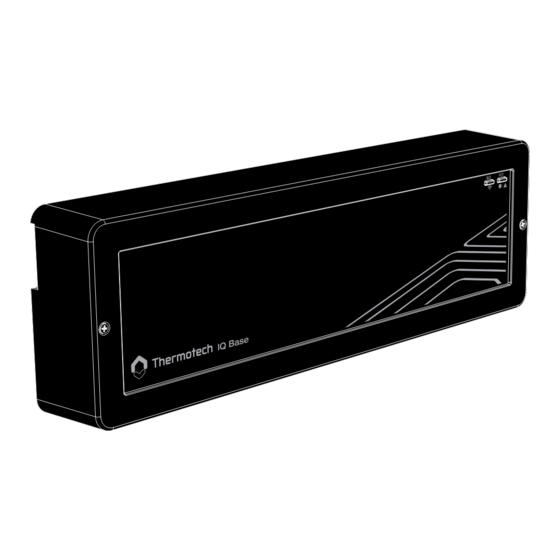
IQ Base
Wireless control unit
(24 VDC)
1
b.
3
01
02
L
L (pump)
N
N
Power
supply
230V~50Hz
230V~50Hz
300W / 500VA max.
4
02
L (pump)
N
230VAC~50Hz
300W / 500VA max.
Warning for pump connection:
electrical hazard, always remove
the power supply from the product
before opening the casing.
Mounting and installation
1
• Only a professional installer is authorised to install and service
the product. Control unit is intended for fixed installation only.
• Loosen the screw in the centre of the connection unit.
• Remove the front cover.
• Remove the lower casing and attach the control unit to the wall
using the attached screws, you can also mount the unit on a
DIN rail.
Connection of thermal actuators
2
• Connect actuators to desired channels on the control unit.
• C1 to C12: only 1 actuator connected per channel.
a.
03
04
µ 2A
C/O
24...230V~
C1
C2
COM NO NC
= Heat.
= Cool.
+24V GND
+24V GND
Pump
5
L
N
Output
contact
L
N
Thermotech - Spårvägen 8 - S-90131 Umeå Sweden
67912
2
C2
C3
C4
a.
+24V GND
+24V GND
+24V GND
05-16
24V DC 3W max. per actuator outputs
C3
C4
C5
C6
C7
C8
C9
C10
+24V GND
+24V GND
+24V GND
+24V GND
+24V GND
+24V GND
+24V GND
+24V GND
6
IQ Base
23
Eco
/
: Bluetooth pairing button / Pairing status indicator (Blue)
(function) /
cator (Green, orange or red)
Pump control
4
• Circulation pump can be connected to the control unit.
• Pump output is turned on when at least one channel is in heat
demand.
ECO-Mode
5
• An external clock could be installed with a time controlled low-
ering of the preset temperature by 3ºC.
Power up
• Once all the wiring is made and the front cover is back on, plug
the control unit on a socket.
IQ Home
C5
C6
C1
C7
C2
C8
C3
C9
C4
+24V GND
+24V GND
+24V GND
+24V GND
+24V GND
+24V GND
+24V GND
+24V GND
+24V GND
Sensors x3
17
20
21
T1
Input
C11
C12
24V DC 2.5W max.
0 -10V/PWM
18
0 -10V
GND
24V DC
T2
+24V GND
+24V GND
19
T3
IQ Room
: Factory reset button / Installation status indi-
MATERIAL
WEIGHT
REVISION
PROJECT
Spårvägen 8
901 31 Umeå
NAME
DATE
TITLE
Sweden
+46620-683330
DRAWN BY
jens
2018-12-05
DWG NO.
APPV'D BY
ENG
C10
C5
C11
C6
C12
C7
+24V GND
+24V GND
+24V GND
+24V GND
+24V GND
+24V GND +24V
BLE
FCT
23
Eco
22
= Comfort
= Eco
Leakage
sensor
GND
IQ Home
SHEET
1 of 1
SCALE
1:1
A3
Advertisement

Summary of Contents for ThermoTec 67912
- Page 1 Quick guide 67912 IQ Base Wireless control unit (24 VDC) IQ Home +24V GND +24V GND +24V GND +24V GND +24V GND +24V GND +24V GND +24V GND +24V GND +24V GND +24V GND +24V GND +24V GND +24V GND...
- Page 2 80% at +25°C (non condensing) SIMPLIFIED EU DECLARATION OF CONFORMITY : Hereby, Thermotech declares that the radio equipment type, Wireless control unit IQ Base/67912, is in compliance with Directive 2014/53/EU. The full text of the EU declaration of conformity is available at the following internet address: https://www.thermotech.se/dokumentation/...
Need help?
Do you have a question about the 67912 and is the answer not in the manual?
Questions and answers