Table of Contents
Advertisement
Quick Links
CONTROLLER MANUAL FOR CHILLERS AND INVERTER
AIR/WATER HEAT PUMPS WITH AXIAL FANS
Models
THRON AGR2
This manual has been created for informative purpose. The company declines any responsibility for the results of any projecting or any installation based on the explanations and/or on
the technical specifications provided in this manual. It is besides forbidden the reproduction under any form of the texts and of the figures contained in this manual.
"This manual is a translation from the official italian language version. For reasons of environmental respect the Company will not provide the hard copy in the original language which
could be directly requested or downloaded from the Company website at any time. In case of any dispute, the original language manual will be the trusted one".
Advertisement
Table of Contents

Summary of Contents for JustFire THRON AGR2
- Page 1 AIR/WATER HEAT PUMPS WITH AXIAL FANS Models THRON AGR2 This manual has been created for informative purpose. The company declines any responsibility for the results of any projecting or any installation based on the explanations and/or on the technical specifications provided in this manual. It is besides forbidden the reproduction under any form of the texts and of the figures contained in this manual.
- Page 2 Controller for Chillers and inverter air / water heat pumps with axial fans 03-2017 08-2014 Date Author Supervisor Serie / Series / Serie / Serie / Série Catalogo / Catalogue / Katalog / Catalogue CONTROLLER FOR CHILLERS AND INVERTER AIR/WATER HEAT PUMPS MCO14124H7820-01 WITH AXIAL FANS Possible wasted electrical or electronic devices/products should not be located together with normal domestic waste, but disposed according to the...
-
Page 3: Table Of Contents
Controller for Chillers and inverter air / water heat pumps with axial fans INDEX CONSERVATION OF THE MANUAL ............................4 GRAPHIC SYMBOLS................................4 PERMITTED USES ................................... 4 GENERAL SAFETY RULES ................................. 4 PERSONAL SAFETY EQUIPMENTS ............................. 4 WORKERS’ HEALTH AND SAFETY ............................4 PURPOSES AND CONTENTS OF THE MANUAL ......................... - Page 4 Controller for Chillers and inverter air / water heat pumps with axial fans 10.12 OPERATION AREA - ACTIVATION OF THE AUXILIARY ELECTRIC HEATER AND BOILER (P LANT CIRCUIT WATER TEMPERATURE SENSOR ) ................................... 20 IS NOT ENABLED 10.12.1 AUXILIARY SYSTEMS OFFSET MANAGEMENT ...................... 23 10.13 SUMMER/WINTER OPERATION INDICATION ........................
-
Page 5: Conservation Of The Manual
Controller for Chillers and inverter air / water heat pumps with axial fans 1 CONSERVATION OF THE MANUAL The manual has to be always kept for future reference. It has to be stored in a safe place, away from dusts and moisture. It has to be also available and accessible to all users who shall consult it any time they are in doubt on how to operate the equipment. - Page 6 Controller for Chillers and inverter air / water heat pumps with axial fans • To step with your feet on the appliance, sit down and/or place any type of object. • To spray or pour water directly on the unit. •...
-
Page 7: Purposes And Contents Of The Manual
Controller for Chillers and inverter air / water heat pumps with axial fans 4 PURPOSES AND CONTENTS OF THE MANUAL This manual provides basic information for the installation, operation and maintenance of CHIP units. It is addressed to machine operators and it enables them to use the equipment efficiently, even if they do not have any previous specific knowledge of it. -
Page 8: Analog Input Menu
Controller for Chillers and inverter air / water heat pumps with axial fans Level 2 (C) = it appears if you enter the manufacturer password. Level 3 (A) = it appears only via Modbus. 5.1.1 ANALOG INPUT MENU By entering the maintainer password in the menu of analog inputs "tP", at the level 1 of the menu structure diagram of the unit control board, you can read the values of the current probes: DESCRIPTION Measurement unit... -
Page 9: Display
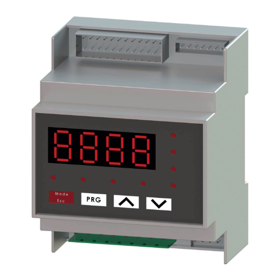
Controller for Chillers and inverter air / water heat pumps with axial fans DISPLAY In Normal view displays the outlet water temperature reported to tenths of degrees, or the alarm code if at least an alarm is active. In case of multiple alarms activation, it will display the first alarm, while the second appears when the first is reset. Into the menu mode, the display depends on the current position where you are. -
Page 10: Dynamic Set-Point Adjustment
Controller for Chillers and inverter air / water heat pumps with axial fans Note: Note that with the adoption of the optional “KIE” module helps to increase the input/output (I/O) ports. For more information, please refer to the related manual of this module. 6 DYNAMIC SET-POINT ADJUSTMENT The controller can change the set-point by adding a value depending on the outdoor air temperature sensor. -
Page 11: Circulator
Controller for Chillers and inverter air / water heat pumps with axial fans - b20=0 when the input is at the actual set point is: set point (Coo/Hea) - b15/2. - b20=0 when the set point will be the set of (Coo/Hea) mode. the input is at 50%, - b20=0... -
Page 12: Operation By Thermoregulator With Periodic Activation
Controller for Chillers and inverter air / water heat pumps with axial fans OPERATION BY THERMOREGULATOR WITH PERIODIC ACTIVATION The function is disabled if P17= 0 (default). If the pump is set to operate by thermoregulation call (P03 = 1, default), it will be activated periodically for a time period defined by the parameter P17 (in seconds) after a counting time set by the parameter P16 (in minutes), activated when the pump is turned off for satisfied thermoregulation. -
Page 13: Purging The System
Controller for Chillers and inverter air / water heat pumps with axial fans In domestic hot water production mode, the pump will operate at the maximum speed. Note: If the parameter r33>0, then the circulator can start operations under call also for the activation of the plant resistance and/or sanitary mode operation, see paragraph.Errore. -
Page 14: Fan Speed Control In Heating Mode
Controller for Chillers and inverter air / water heat pumps with axial fans run at preset minimum fan speed. This function has the purpose to prevent the compressor startup at very high condensation temperatures. FAN SPEED CONTROL IN HEATING MODE The fan speed control in heating mode occurs depending on the diagram shown below, where: F17 = Pressure set for the minimum speed of the fan motor in heating mode F18 = Fan motor proportional band in heating mode... -
Page 15: Sensor Memorization In Heating Mode
Controller for Chillers and inverter air / water heat pumps with axial fans I/O Ports - Parameter Value Function 0 (default) Disenabled function Function is active in heating and cooling mode. The remote on-off function doesn’t disenable the DHW production. Function is active in heating and cooling mode. -
Page 16: Heating Mode On Sanitary Accumulation
Controller for Chillers and inverter air / water heat pumps with axial fans i-HWAK 4 i-HWAK 4 i-HWAK 4 i-HWAK 4 10.4 HEATING MODE ON SANITARY ACCUMULATION If the parameter H83=1, the appliance exploits the accumulation tank for sanitary hot water also to heat the plant side. In these conditions, the relay which controls the sanitary valve will be also energized during heating operation and not only in sanitary mode. -
Page 17: Remote Functions
Controller for Chillers and inverter air / water heat pumps with axial fans 10.5 REMOTE FUNCTIONS The terminal block provides the digital inputs to control the unit via an external consent. 10.5.1ON/OFF The ON/OFF function is enabled by default on the digital input “ID2” (terminals: ON/OFF-ON/OFF). Remove the bridge of the terminal block then the unit will be placed in stand-by mode (in such status the display of the on-board unit controller will show the "E00"... -
Page 18: Remote Sensor For The Water Temperature Of The Plant Circuit
Controller for Chillers and inverter air / water heat pumps with axial fans 10.6 REMOTE SENSOR FOR THE WATER TEMPERATURE OF THE PLANT CIRCUIT In some configurations of systems (example: heat pump in parallel with a boiler on the same hydronic circuit and diverter valve of exclusion) it could be necessary to enable a plant temperature sensor to allow the on-board unit controller to correctly process the management. -
Page 19: Electric Heater Of Sanitary Water Production
Controller for Chillers and inverter air / water heat pumps with axial fans 10.7.3ELECTRIC HEATER OF SANITARY WATER PRODUCTION It is an additional energy resource for the sanitary water tank heating when the compressor is not able to reach the set temperature within a reasonable time. -
Page 20: Activation Of Auxiliary Electric Heaters And Boiler During The Joint And In Substitution Operation To The Compressor Of The Heat Pump
Controller for Chillers and inverter air / water heat pumps with axial fans - r32 = 0: boiler without a circulating pump with thermoregulation to be performed by the heat pump unit. - r32 = 1: boiler equipped with independent circulating pump with thermoregulation to be performed by the heat pump unit. - r32 = 2: boiler without circulating pump with independent thermoregulation. -
Page 21: In Substitution Operation
Controller for Chillers and inverter air / water heat pumps with axial fans activated, and then will be deactivated when the measured temperature by the remote sensor is greater than setpoint Hea. The heat pump follows the activation logic described in paragraph 10.6. The boiler will be managed by the outlet temperature sensor of the heat pump if the water plant circuit remote sensor is not active. - Page 22 Controller for Chillers and inverter air / water heat pumps with axial fans TABLE 2. JOINT OPERATION, AREA 1 ORDER OF INTERVENTION OF N° HEATING SYSTEMS (when the set- MODE OPERATION point is not achieved) 1) Heat pump HEAT / Set up of 2) After r12 minutes, auxiliary HEAT...
- Page 23 Controller for Chillers and inverter air / water heat pumps with axial fans 1) Boiler Set up of 2) After r15 minutes, auxiliary electric HEAT+SAN SANITARY minutes heater of sanitary 3) After r15 minutes later, heat pump 1) Boiler 2) After r15 minutes, heat pump Set up of HEAT+SAN SANITARY...
-
Page 24: Auxiliary Systems Offset Management
Controller for Chillers and inverter air / water heat pumps with axial fans The below Table (5) shows the parameter to be set in order to enable the auxiliary electric heaters in "Summer and sanitary" mode (in this case, the only available auxiliary electric heater is the one of sanitary side and the subdivision between normal/joint/substitution operation is not valid). -
Page 25: Summer/Winter Operation Indication
Controller for Chillers and inverter air / water heat pumps with axial fans In this way, the heat pump will stop when achieving the set-point (G02, G03, G05) and the temperature difference can be supplemented by the boiler and/or electric heaters according to the selected temperature offset. 10.13SUMMER/WINTER OPERATION INDICATION It is possible to set a digital output in order to indicate the operating mode of the unit, plant side. -
Page 26: Maximum Hz
Controller for Chillers and inverter air / water heat pumps with axial fans 10.17Maximum Hz This function is disabled by default. To activate the Maximum Hz function, you should set the parameter L02 to the value L02=1, the cooling and heating capacities will increase with 10% (depending on the heat pump model and working conditions). -
Page 27: Humidistat Operation
Controller for Chillers and inverter air / water heat pumps with axial fans The 3-way valve with 2 or 3 contacts for power supply connection The 3-way valve is applied to divert the water flow between floor plant and fan coil units. In the case of a 3-way valve with 2 contacts for power supply (with return spring), when the 3-way valve is not activated, the outlet of the valve that is opened must be connected to the floor plant. -
Page 28: Humidistat Wiring
Controller for Chillers and inverter air / water heat pumps with axial fans 10.18.6 HUMIDISTAT WIRING Carry out the following connections between the humidistat and the terminal block of the minichiller unit: • Connect POWER SUPPLY to 12V+ and 12V-. •... -
Page 34: Alarms
15 ALARMS 15.1 WATER FLOW SWITCH ALARM E06 The water side flow switch is already installed inside the unit and DOES NOT HAVE to be tampered with or by-passed in any way. The flow switch is by-passed for 10 seconds after the unit’s start up. The alarm signal occurs after 5 seconds of the error appearance (lack of water flow, air inside the circuit, etc.). -
Page 35: Power Failure
Controller for Chillers and inverter air / water heat pumps with axial fans 15.12POWER FAILURE After power supply reset: 1. The system comes back to the previous state before the power failure. 2. If the system is defrosting, this mode will be cancelled after power supply reset. 3.
Need help?
Do you have a question about the THRON AGR2 and is the answer not in the manual?
Questions and answers