
Summary of Contents for Messana ATU150H
- Page 1 Vertical and horizontal Air Treatment Units (ATU) Neutral Temperature Dehumidifier (NTD) with high efficiency heat recovery ventilation (HRV) M A I N T E N A N C E , I N S T A L L A T I O N A N D U S E R M A N U A L...
- Page 2 Each unit comes with “Installation and Operation Manual” (this manual) and additional documents: Cutsheet (it includes dimensional drawings and clearances) Wiring diagram The reproduction of this document, even partial, without Messana Inc. written authorization, is strictly forbidden Maintenance, installation and user manual – Rev 03...
- Page 3 For necessary ordinary or extraordinary maintenance operations, we remain at your disposal with our Technical support Service, to assist you and supply the spare parts. For a quicker assistance, please contact us at the following references: MESSANA RADIANT COOLING radiantcooling.com 4105 Soquel Ste B, Soquel CA 95073 +1 (855) RAY-MAGIC (729-6244) Maintenance, installation and user manual –...
-
Page 4: Table Of Contents
Air Treatment Unit SUMMARY INTRODUCTION ..........................5 RESPONSABILITIES ................................. 5 SERVICE RULES ..................................7 USES ...................................... 7 RESIDUAL RISK AREAS ................................8 INTERVENTION AND MAINTENANCE ............................. 8 GENERAL SAFETY RULES ................................ 9 PRODUCT DESCRIPTION ........................ 10 SERIES ....................................11 AIR FLUXES ................................... 12 STRUCTURE .................................. -
Page 5: Introduction
Air Treatment Units INTRODUCTION The present MIUM indicates the uses of the unit and gives instructions for transport, installation, assembling and regulation of the unit. It gives directions about maintenance, spare parts’ request, residual risks presence and staff education. This manual should be read and used in the following way: Each operator and person concerned with the use and maintenance of the unit, should read it carefully and follow the instructions it gives;... - Page 6 Air Treatment Unit Maintenance, installation and user manual – Rev 03...
-
Page 7: Service Rules
Air Treatment Units SERVICE RULES The service rules described in this manual have to be considered as integral part of the unit supplied. Moreover, these rules are reserved to the operator, who has previously been instructed about the unit in object and they provide necessary information about safety and correct use of the machine. -
Page 8: Residual Risk Areas
Air Treatment Unit RESIDUAL RISK AREAS Due to the peculiar functionality of the unit, in some areas of it, there are residual risks which was not possible to elude during the project neither to reduce. Each operator should be aware of the residual risks in this unit and to follow the safety rules, in order to avoid accidents. -
Page 9: General Safety Rules
Air Treatment Units Pay attention to under-pressure pipes integrity and check that there are not liquid losses. Check that there are no liquid or dangerous substances losses. If this happens, the operator should not turn the unit on before having solved the problem. GENERAL SAFETY RULES Safety clothes Operators should wear safety... -
Page 10: Product Description
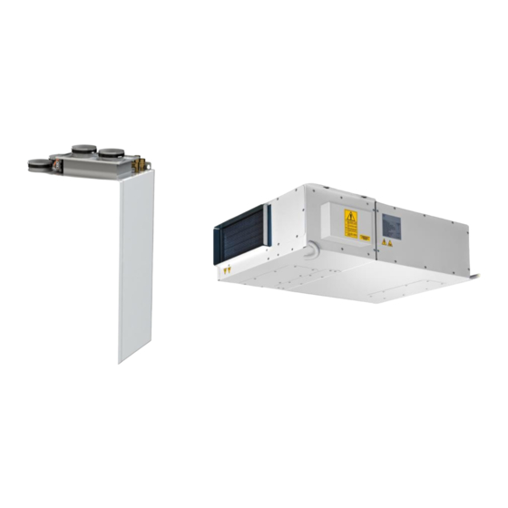
Air Treatment Unit PRODUCT DESCRIPTION Messana ATU units are conceived for a use in civil, residential and commercial ambiences, with high latent load and for a 24h/day functioning. They are strongly suggested for places where there are cooling radiant systems: underfloor, walls, ceiling. -
Page 11: Series
Air Treatment Units SERIES There are 21 available models, classified according to the dehumidification capacity (150, 230, 300...) and to the version (W-A-I): ATU150H W ATU150H A ATU150H I ATU230H W ATU230H A ATU230H I ATU300H W ATU300H A ATU300H I... -
Page 12: Air Fluxes
Return from ambient (normally the corridor) for recirculation within the house Exhausted air extraction (from “dirty” ambient such as bathrooms, kitchens, laundry...) Fresh air inlet Exhausted air expulsion outside Airflows vary according to the model: ATU150H/V ATU230H/V Supply in ambient max 150 CFM max 230 CFM... - Page 13 Air Treatment Units ATU 150 H and ATU 230 H – only recirculation mode Return from ambient Supply in ambient ATU 150 H and ATU 230 H – only renewal mode Supply in ambient Exhausted air extraction Fresh air inlet Exhausted air expulsion ATU 150 H and ATU 230 H –...
- Page 14 Air Treatment Unit ATU 300 H – only recirculation mode Return from ambient Supply in ambient ATU 300 H – only renewal mode Exhausted air Supply in ambient extraction Fresh air inlet Exhausted air expulsion ATU 300 H – recirculation + renewal mode Return from ambient Exhausted air Supply in ambient...
- Page 15 Air Treatment Units ATU 600 H – only recirculation mode Return from ambient Supply in ambient ATU 600 H – only renewal mode Exhausted air extraction Supply in ambient Exhausted air Fresh air inlet expulsion ATU 600 H – recirculation + renewal Exhausted air Return from ambient extraction...
- Page 16 Air Treatment Unit ATU 150 V – only recirculation mode ATU 150 V – only renewal mode Supply in Exhausted air Fresh air ambient expulsion inlet Exhausted air extraction Supply in ambient Return from ambient ATU 150 V – recirculation + renewal Exhausted air expulsion Fresh...
- Page 17 Air Treatment Units ATU 230 V – recirculation mode ATU 230 V – renewal mode Fresh air inlet Ambient supply Ambient supply Exhausted air extraction Exhausted air expulsion Return from ambient Fresh air inlet ATU 230 V – renewal and recirculation mode Ambient supply Exhausted air extraction Exhausted air expulsion...
- Page 18 Air Treatment Unit ATU 300 V – recirculation mode ATU 300 V – renewal mode Exhausted air expulsion Return from ambient Ambient supply Return from ambient Ambient supply Fresh air inlet ATU 300 V – renewal and recirculation mode Exhausted air extraction Exhausted air expulsion Ambient supply Fresh air inlet...
- Page 19 Air Treatment Units General air treatments and air fluxes scheme FRESH AIR AIR TREATMENT active (max 5/5) active (min 1/5) inactive (0/5) Heating Cooling Cooling eco Dehumidification Dehumidification & Cooling RECIRCULATION (50% fresh air + (10% fresh air + (100% recirculation + 0% fresh air) 50% recirculation) 90% recirculation) Treatment...
-
Page 20: Structure
Air Treatment Unit STRUCTURE The unit is realized with an exclusive design which grants the complete inaccessibility, when the unit is closed. This, together with the use of sound absorbent material, helps in the reduction of the sound level of the unit. The majority of the panels, are removable ones, in order to grant a complete accessibility to the unit, even if for ordinary maintenance, the accessibility is from the lower part of the unit. -
Page 21: Functions
Air Treatment Units FUNCTIONS Electronic fans with brushless motor and inverter integrated Regulation graphic display with temperature and humidity probes 5 speeds regulation for fresh air Dirty filter timed signal Detailed anomaly signal Boost mode ... -
Page 22: Refrigerant And Hydraulic Circuits
Air Treatment Unit REFRIGERANT AND HYDRAULIC CIRCUITS FUNCTIONAL SCHEMES Model W (water) Model A (isothermal) Model I (hybrid) LEGEND Compressor Pre-cooling water coil Evaporator Condenser Post-cooling water coil High pressure safety switch Throttling device Two ways water valve 10. Water condenser 11. -
Page 23: Electrical Circuits
Air Treatment Units ELECTRICAL CIRCUITS ELECTRICAL DEVICES The electrical panel is realized and wired according to the Regulations mentioned in the Declaration of Conformity. You should add a fuse to the domestic electrical implant, in order to protect the unit. All the remote commands are realized with low tension, supplied by an insulation transformer. -
Page 24: Main Screen
Air Treatment Unit MAIN SCREEN KEYS’ USE OFF to turn off the unit Keep pressed EXIT to display temporarily software version MENU to enter the user menu Operating mode on the top, indicates the current day 08:22 on the right top, indicates the current None symbol: manual mode time time bands active... - Page 25 Air Treatment Units Now we see in detail the possible screens of the ‘user menu’: Screen 1 allows to set the functioning of the unit: MANUAL: desired humidity, desired temperature, on/off, fresh air: they are all values modifiable from the dedicated screens TIME-BANDS: on/off of the unit, desired humidity, desired temperature, fresh air: these values are going to function according to the time-bands program you set AUTOMATIC: humidity and temperature are pre-set to optimal values and are not...
- Page 26 Air Treatment Unit Screen 5 allows to set the desired humidity (the screen appears if: there are alarms) press OK to enter the alarm menu press EXIT to exit and come back to the main screen press UP to come back to the previous screen press DOWN to go to the next screen Screen 6 allows to program time-bands (the screen does not appear if: the unit is managed from a serial Modbus or if it is not set in time-...
-
Page 27: Alarms Menu
Air Treatment Units ALARMS MENU This menu is available only if there is an alarm on the unit and it allows to display the active alarm and, if possible, to reset it. The screen allows to choose whether to display the alarm or to reset it: press EXIT to exit and come back to the main screen press UP and DOWN to select what to do press OK to confirm the choice and to shift to the following screen... -
Page 28: Time Bands Menu
Air Treatment Unit TIME BANDS MENU This menu is accessible only if the unit is set in time-bands mode and allows to program the bands which manage the on/off of the unit, the summer temperature, the winter temperature, the humidity and the fresh air. It is fundamental to set the current date and time, go to screen 7 of the User menu (additional information in the previous chapter) Default values are:... -
Page 29: Other Screens
Air Treatment Units Guide Selecting this guide, you have access to 5 screens which explain how to realize the time bands program. KEYS’ USE: - With UP and DOWN you slide from a screen to another (5 total screens) - With EXIT you come back to the previous screen Default recovery The first time you program the time bands, it may occur that you make something wrong or that you program the time bands but, after a while, you realize that the program is not the most suitable: in both these cases you have the possibility to delete the whole... -
Page 30: Technical Data
Air Treatment Unit TECHNICAL DATA TECHNICAL DATA SHEET ATU150H COMPRESSOR reciprocating reciprocating type REFRIGERANT CIRCUITS REFRIGERANT GAS R134a R134a type REFRIGERANT CHARGE DEHUMIDIFICATION CAPACITY (1) US pints/day EFFICIENCY HEAT RECOVERY IN WINTER (2) EFFICIENCY HEAT RECOVERY IN SUMMER (3) TOTAL COOLING CAPACITY... - Page 31 Air Treatment Units ATU230H ATU300H COMPRESSOR reciprocating reciprocating reciprocating reciprocating type REFRIGERANT CIRCUITS REFRIGERANT GAS R134a R134a R134a R134a type REFRIGERANT CHARGE DEHUMIDIFICATION CAPACITY (1) US pints/day EFFICIENCY HEAT RECOVERY IN WINTER (2) EFFICIENCY HEAT RECOVERY IN SUMMER TOTAL COOLING CAPACITY 9200 8100 12400...
- Page 32 Air Treatment Unit ATU600H ATU150V COMPRESSOR rotary rotary reciprocating reciprocating type REFRIGERANT CIRCUITS REFRIGERANT GAS R410A R410A R134a R134a type REFRIGERANT CHARGE DEHUMIDIFICATION CAPACITY (1) US pints/day EFFICIENCY HEAT RECOVERY IN WINTER (2) EFFICIENCY HEAT RECOVERY IN SUMMER TOTAL COOLING CAPACITY 26000 23000 6500...
- Page 33 Air Treatment Units ATU230V ATU300V COMPRESSOR reciprocating reciprocating reciprocating reciprocating type REFRIGERANT CIRCUITS REFRIGERANT R134a R134a R134a R134a type REFRIGERANT CHARGE DEHUMIDIFICATION CAPACITY (1) US pints/day EFFICIENCY HEAT RECOVERY IN WINTER (2) EFFICIENCY HEAT RECOVERY IN SUMMER TOTAL COOLING CAPACITY 9200 8100 12400...
-
Page 34: Airflows And Pressure
Air Treatment Unit AIRFLOWS AND PRESSURE All our horizontal ATU units mount electronic radial fans with inverter integrated and brushless engine. Please make reference to the installation paragraph to calibrate the unit. SUPPLY ATU150H/V EXTRACTION ATU150H/V SUPPLY ATU230H/V EXTRACTION ATU230H/V... - Page 35 Air Treatment Units SUPPLY ATU600H EXTRACTION ATU600H 1000 1500 On the vertical line you see the load losses, while on the horizontal one, you find the different airflows. Lower curve = suggested limitation Upper curve = max limitation Maintenance, installation and user manual – Rev 03...
-
Page 36: Dehumidification Performance
Air Treatment Unit DEHUMIDIFICATION PERFORMANCE ATU150H/V I 4000 86°F/65% 86°F/65% 86°F/55% 86°F/55% 3500 77°F/65% 77°F/65% 3000 77°F/55% 77°F/55% 2500 2000 1500 1000 42,5 47,5 52,5 57,5 62,5 42,5 47,5 52,5 57,5 62,5 Water temperature [°F] Water temperature [°F] ATU230H/V I 6500 86°F/65%... - Page 37 Air Treatment Units ATU600H I 20500 86°F/65% 86°F/65% 18500 86°F/55% 86°F/55% 77°F/65% 16500 77°F/65% 77°F/55% 77°F/55% 14500 12500 10500 8500 6500 4500 2500 42,5 47,5 52,5 57,5 62,5 42,5 47,5 52,5 57,5 62,5 Water temperature [°F] Water temperature [°F] Maintenance, installation and user manual – Rev 03...
-
Page 38: Hydraulic Circuit Load Losses
Air Treatment Unit HYDRAULIC CIRCUIT LOAD LOSSES ATU150H/V W ATU150V/H A/I ATU230H/V W ATU230H/V A/I ATU300H/V W ATU300H/V A/I Maintenance, installation and user manual – Rev 03... - Page 39 Air Treatment Units ATU600H W ATU600H A On the vertical line you see the load losses of water flow, while on the horizontal one you find the flows. Maintenance, installation and user manual – Rev 03...
-
Page 40: Heating Capacity - Model I
Air Treatment Unit HEATING CAPACITY – MODEL I Air ambient conditions: 68°F, 50% RH ATU150H/V I ATU230H/V I 5000 8000 7000 4000 6000 5000 3000 4000 2000 3000 2000 1000 1000 Water Temperature (°F) Water Temperature (°F) ATU300H/V I ATU600H I... -
Page 41: Maintenance And Troubleshooting
Air Treatment Units MAINTENANCE AND TROUBLESHOOTING FAULTS AND ANOMALIES In the following pages you find the more frequent possible causes of block or dysfunction of the unit. The classification is made on easy-to-identify signs. When executing the operations suggested to solve the problem, be careful: an excessive self- confiance can be dangerous. - Page 42 Air Treatment Unit ANOMALY POSSIBLE CAUSES WHAT TO DO Probe’s anomaly Check the status of the probe Water temperature probe’s (errors may be caused by short-circuit or If the problem is not solved, replace the alarm probe interruption) probe Probe’s anomaly Check the status of the probe Water coil anti-freeze (errors may be caused by short-circuit or...
-
Page 43: Maintenance Table
Air Treatment Units MAINTENANCE TABLE Units will operate correctly only if the maintenance operation suggested in the table are executed following the period indicated. Operation Period Air filters Visual check and cleaning every 6 months (or more frequently in case of dirty ambiences) ... -
Page 44: Ordinary Maintenance
By removing access’ panels, filters may fall down. Pay attention to avoid their fall out. ATU150H and ATU230H Panel with external air and exhaust air filters Panel with condensate tray and heat recovery unit Panel with supply air filter... - Page 45 Air Treatment Units ATU150V and ATU230V 1. External air and exhaust air filters 2. Condensate tray and heat recovery unit 3. Expulsion fan 4. Supply fan 5. Recirculation air filter ATU300V External air and exhaust air filters Extraction air filter Recirculation air filter Condensate tray and heat recovery unit Expulsion fan...
-
Page 46: Extraordinary Maintenance
Air Treatment Unit EXTRAORDINARY MAINTENANCE The extraordinary maintenance has to be done only by qualified staff. DO NOT IMPROVISE, WOUND OR DEATH DANGER Thermal exchange coil cleaning Remove the amassments of dust or crusts by washing the pack with compressed air in opposite sense according to air flux; or, as an alternative, wash it with water and non-corrosive products. -
Page 47: Installation
Type of installation Units ATU H have to be installed by hanging it; Units ATU150H and ATU230H have to be installed on the wall; Units ATU300H have to be installed on the floor. Installation of units ATU H and ATU150V and ATU230V have to be done using screws or bolts properly designed and it is necessary to evaluate the strength of the wall or the ceiling. -
Page 48: Clearances
10.3 CLEARANCES The clearances of all units are included in the “Cutsheet”. ATU UNITS (horizontal) For false-ceiling installations, consider the predisposition of a removable panel under the unit. Size ATU150H ATU230H ATU300H ATU600H ATU UNITS (vertical) AT SIGHT INSTALLATION (ATU150V and ATU230V) For on-wall on sight installations, respect the clearances indicated in the following pictures: Maintenance, installation and user manual –... - Page 49 Air Treatment Units FLOOR STANDING UNIT (model ATU300V) For floor standing unit, respect the clearances indicated in the following pictures: Maintenance, installation and user manual – Rev 03...
-
Page 50: Hydraulic Connections
Air Treatment Unit 10.4 HYDRAULIC CONNECTIONS WATER CIRCUIT CONNECTION When realizing the hydraulic circuit, it is compulsory to follow the below indications and also the national / local regulations Do not twine on the connections of the unit. With a key, block the connection and with another one, fix the adaptor. -
Page 51: Electrical Connections
Air Treatment Units 10.5 ELECTRICAL CONNECTIONS “Wiring diagram” of the unit is attached to this document, refers to it for all the information about the electrical connections. Open the electrical panel, introduce the supply cable and the other necessary cables on the dedicated holes, realize the connections on the clamps and close the panel. - Page 52 Air Treatment Unit CONFIGURABLE DRIVES Clamps (17-IC) - (18-IC) - (19-IC) - (20-IC) are the configurable drives; they are 4 digital inputs that you can configure to do several functions. ATTENTION: connect only the clean contacts and not the tension ones. POSSIBLE CONFIGURATIONS OPEN CONTACT CLOSED CONTACT...
- Page 53 Air Treatment Units DISPLAY The display and the cable are inside the electrical panel, pay attention not to make them fall. PLACING AND FIXING OF THE DISPLAY The display should be installed in a practical position, so that the user can execute the fundamental operations, display the functioning status of the unit and, eventually, the alarms.
-
Page 54: First Starting, Calibration And Configuration
Air Treatment Unit RS485 CONNECTION-MODBUS Connect the Modbus RS485 cable on the removable clamp indicated on the picture on the left. Respect on all the connected devices, the connection A and B and connect on the GND connection the shielded. For the Modbus parameters’... - Page 55 Air Treatment Units Here below you find the pictures with the points in which you have to measure during calibration. Make reference to this page during all the calibration process. ATU150H ATU230H DUCT 1 DUCT 1 DUCT 3 DUCT 3...
- Page 56 Air Treatment Unit ATU230V FROM THE TOP ATU230V FROM DOWN DUCT 3 DUCT 2 DUCT 1 DUCT 4 ATU300V FROM THE TOP ATU300V FRONT DUCT 3 DUCT 2 DUCT 1 DUCT 4 DUCT 4 DUCT 1 DUCT 2 – EXHAUSTED AIR EXPULSION FROM EXPULSION –...
- Page 57 Air Treatment Units CALIBRATION - PHASE 1 Place on the display; press EXIT (more times, if necessary) or press ON/OFF if the unit is turned off in order to enter the main screen. If for 30 seconds, on the installer menu, no key is pressed the main screen is displayed. In this case, repeat the process from phase 1.
- Page 58 Air Treatment Unit CALIBRATION - PHASE 3 Press DOWN to move to the phase 3 of the calibration: in this phase you will calibrate the unit in recirculation and renewal mode. To do this, you will have to modify the values of speeds for supply fan and the opening of the recirculation damper. The screen displays 2 parameters (the higher one indicates the % of supply fan rotation, while the lower one indicates the % of opening for the recirculation damper).
- Page 59 Air Treatment Units INSTALLER’S PARAMETERS CONFIGURATION To enter the installer menu: Place on the main screen (press EXIT if necessary) Keep pressed for 3 seconds UP, OK and DOWN Insert ‘0010’ as password and press OK to confirm If for 30 seconds, on the installer menu, you do not press any keys, the program will automatically exit and you will display the main screen.
- Page 60 Air Treatment Unit Possible configuration of the adjustable control for supply temperature: you can decide whether to do the regulation for the manual heating “from supply probe” or “from ambient probe”. default: from supply probe Possible modification of the cooling management. Possible configuration of the dew-point control (dew-point, condensation point) This function allows to the unit to control precisely when inside the habitation, in summer, there is the risk of condensation on the radiant panels and of soaking the involved surface of the panels.
- Page 61 Air Treatment Units Possibility to modify the reading of the temperature and humidity probes. Default: 0.0 °F and 0% Possibility to set the configurable output/exit: The exit could be inactive, set as ‘general alarm’ or as ‘dew-point alarm’. For each command set, it is possible to reverse the logic. For the electrical connection and other information, please make reference to the previous pages.
- Page 62 MESSANA RADIANT COOLING radiantcooling.com 4105 Soquel Ste B, Soquel CA 95073 +1 (855) RAY-MAGIC (729-6244)
Need help?
Do you have a question about the ATU150H and is the answer not in the manual?
Questions and answers