Table of Contents
Advertisement
Quick Links
Advertisement
Table of Contents

Summary of Contents for Hokuyo UGM-50LAP
- Page 1 2D Lidar Scanning Laser Range Finder UGM-50LAP...
-
Page 2: Detection Area
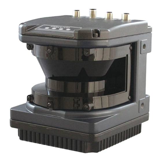
1. General The UGM-50LAP scans a semicircular field using a laser beam (λ= 905 nm), then calculates coordinates by measuring the distance to an object and its corresponding step angle and detects obstacles within the setting area. ・ This product can output distance data using the communication protocol SCIP. - Page 3 2. Disclaimer ・ The UGM-50LAP (hereafter referred as sensor) is not certified for functional safety. ・ This sensor cannot be used for human body detection as per the machinery directives. ・ This sensor emits laser for measurement. Sensor’s operation may become unstable under the influence of strong interference light or when emitted lights are not reflected back from object.
-
Page 4: Product Specs
UGM-50LAP 3. Product Specs Product Name 2D LiDAR Model UGM-50LAP Light source Laser semiconductor (905nm), FDA Laser Safety Class 1 (IEC60825-1:2014) Supply voltage DC 24V +/-10% Steady state current: 1A or less, Starting Current: 1.5A or less, without Heater *1... - Page 5 Specifications (continued) -10 to +50°C below 85%RH Ambient temperature and humidity -30 to +50°C below 85%RH (While using the heater) (Without dew, frost) A measured distance will be shorter than an actual distance under the influence of rain, Environment e ect snow and direct sunlight.*7 10 to 150Hz 5G Vibration resistance...
-
Page 6: Power Supply Connector
4. Connection 4.1 Power supply connector M12 4 core A-code socket (Female) PIN No. Function Sensor power supply +V (24V±10%) Sensor power supply GND -V (0V) Heater power supply (24V±10%) Heater power supply GND(0V) 4.2 Ethernet Connector M12 4 core D-code plug (Male) PIN No. -
Page 7: Input/Output Circuit
4.4 Input/output circuit Input: Photocoupler input (Cathode common, 5mA during each input ON, 0.5 mA or below during OFF) Output : Open-collector output Item Specification Maximum output current 50mA Maximum voltage Output residual voltage 1V or less +COM Power supply range 24±10%V Example of connecting the input/output circuit Internal Circuit... -
Page 8: Control Signal
SCIP. Refer to troubleshooting table in section 6 for error details. 5.2 Synchronization output The UGM-50LAP outputs a pulse of 1ms every one scan for synchronizing with the scanning. The timing of the synchronization signal is shown in the figure below. - Page 9 5.4 Synchronization input In a multiple connection of UGM-50LAP, you can synchronize with motor rotation inside each sensor. By connecting the synchronization input terminal of the slave to both synchronization master output terminal and the synchronization input terminal of the master, you can synchronize the motor rotation of the slave with the motor rotation of the master.
- Page 10 When the synchronization master output of the master is connected to the synchronization input of the slave, the master sensor can synchronize falling edges of the synchronization master output signal with falling edges of the synchronization output signal. When the phase value is set, the synchronization output with the phase is shifted by the set value only. Error of phase setting should be within 1ms.
- Page 11 5.10 Area input and selection area set The setting of three regions are available for one area. The three regions correspond to the detection output 1, output 2, and output 3 respectively. You can select an area set number by switching the area input 1 to input 4. The setting of 15 patterns are available.
- Page 12 ON (High level). In a malfunction state, each detection output is switched to OFF state. Example of detection outputs for object A, B and C are as shown below Detection Output 2 Detection Output 3 Position of objects Detection Output 1 UGM-50LAP...
-
Page 13: Troubleshooting
6. Troubleshooting 6.1 Error code table You can obtain the causes of errors from STAT line of the “II” command response in the communication protocol SCIP. The error codes and solutions from the STAT line are as follows in table. Message Meaning Solution... -
Page 14: Heater Function
7. Heater function The UGM-50LAP has a heater inside the product to prevent dew condensation on the optical window. You can select either “Active” or “Inactive” using the application software. The initial operation mode of the heater function is Inactive. When the heater function is activated, the heater will operate if the temperature inside the product decreases below 0° C. When the temperature inside the product increases more than 10° C, the heater will stop its operation automatically. 8. Optical window contamination warning function This function is enabled “Active” using the application software. When this function is enabled “Active”, contamination output will switch to ON (High) if the optical window is contaminated above certain level. The UGM-50LAP will continue to operate and there will be no malfunction stop. 9. Ethernet setting This function is enabled “Active” using the application software. When this function is enabled “Active”, contamination output will switch to ON (High) if the optical window is contaminated above certain level. The UGM-50LAP will continue to operate and there will be no malfunction stop. 9.1 Default value IP default value : 192.168.0.10 Port number : 10940 9.2 About changing IP address You can change IP address using a dedicated application software. 9.3 IP address initialization...
Need help?
Do you have a question about the UGM-50LAP and is the answer not in the manual?
Questions and answers