
Related Manuals for UTECH UT100

Summary of Contents for UTECH UT100
- Page 1 UT100 Handheld Pulse Oximeter Service Manual - English Version 1.0, June 2011 © 2011 UTECH Co., Ltd. All rights reserved.
-
Page 3: Table Of Contents
Table of Contents Table of Contents Chapter 1: Introduction ............1-1 1.1 About this Manual ..............1-1 1.2 Technical Description ............1-1 1.3 Manufacturing Quality & Safety..........1-1 1.4 Declaration of Conformity with European Union Directive ..1-1 1.5 Limited Warranty..............1-2 Service Support ................1-2 Chapter 2: General Description..........2-1 2.1 Intended Use ................ 2-1 2.2 Patient Safety ............... 2-1 2.3 Warning Information ............2-1 2.4 Definition of Symbols............2-3 2.5 Preparation for Use............... 2-4 2.5.1 Getting Acquainted ..............2-4 2.5.2 Power Supply Options ..............2-6 2.5.3 Power On/Off ................ - Page 4 Table of Contents 5.1 Standard Configuration ............5-1 5.2 Optional Accessories .............5-1 Chapter 6: Maintenance and Troubleshooting .......6-1 6.1 Schedule of Maintenance ............6-1 6.2 Cleaning and Sterilization ............6-1 6.2.1 Pulse oximeter ................6-1 6.2.2 SpO2 Finger Sensor ............... 6-1 6.3 Storage..................6-2 6.4 Assembly Exchanges ..............6-2 6.4.1 Internal Assemblies ..............6-2 6.4.2 Reassembling the oximeter............6-3 6.3 Troubleshooting ..............6-3 Chapter 7: Specification ............7-1 7.1 Equipment Classification ............7-1 7.2 SpO ..................7-1 7.3 Pulse Rate ................7-1 7.4 Default Settings of Alarms Limits ...........7-1 7.5 Power Requirements .............7-1 7.6 Battery Life................7-2 7.7 Dimensions................7-2 7.8 Environmental Specification ..........7-2 Chapter 8: Drawings ..............8-1...
-
Page 5: Chapter 1: Introduction
1.1 About this Manual This manual is written for technical personnel servicing the UT100 Handheld Pulse Oximeter. This document contains information which is proprietary and property of UTECH CO., LTD. And may not be reproduced, stored in a retrieval system, translated, transcribed, or transmitted, in any form, or by any means, without the prior explicit written permission of UTECH CO., LTD. UTECH reserves the right to change specification without notice. 1.2 Technical Description... -
Page 6: Limited Warranty
Except as set forth herein, seller makes no warranties, either expressed or implied, including the implied warranties of merchantability and fitness for a particular purpose. No warranty is provide if the products are modified without the express written consent of UTECH company and seller shall not be liable in any event for incidental or consequential damage. This warranty is not assignable. -
Page 7: Chapter 2: General Description
Chapter 2: General Description Chapter 2: General Description 2.1 Intended Use The UT100 Handheld Pulse Oximeter is a low cost monitor for spot checking, continuous, noninvasive monitoring or recording of functional oxygen saturation of arterial hemoglobin (SpO ), pulse rate and pulse strength. The monitor is a battery powered pulse oximeter. It may be used in the hospital, clinical environment, homecare, and during emergency land transportation. The oximeter works with given sensors providing SpO and pulse rate on all patients from neonatal to adult. - Page 8 Chapter 2: General Description KEYWORD DEFINITION WARNING Tells you something that could hurt the patient or hurt the operator. CAUTION Tells you something that could damage the device. NOTE Tells you other important information. Warnings WARNING! ELECTRICAL SHOCK HAZARD when cover is removed. Do not remove covers. Refer servicing to qualified personnel. WARNING! EXPLOSION HAZARD: Do NOT use the device in the presence of flammable anesthetics. Use of this instrument in such an environment may present an explosion hazard. WARNING! Failure of Operation: If the monitor fails to respond as described, do not use it until the situation has been corrected by qualified personnel. WARNING! Patient Safety: Care should be exercised to assure continued peripheral perfusion distal to the SpO2 sensor site after the application. WARNING! Do not position the sensor cable in any manner that may cause entanglement or strangulation. Cautions CAUTION! Do not operate the device when it is wet due to spills or condensation. CAUTION! Do not operate the product if it appears to have ben dropped or damaged.
-
Page 9: Definition Of Symbols
Chapter 2: General Description CAUTION! Avoid storing the monitor at temperatures less than -10C or greater than +55C (<14F or >131 F0) 10-95% R.H. non-condensing. Notes NOTE! Use only the manufacturer approved sensors and accessories with the device. NOTE! The product and its accessories with have patient contact are free of latex. NOTE! Data Validity: As with all pulse oximeters, inaccurate SpO2 and Pulse Rate values may be caused by: Incorrect application or use of a sensor Significant levels of dysfunctional hemoglobin; carboxyhemoglobin or methemoglobin Significant levels of indocyanine green, methylene blue, or other intravascular dyes Exposure to excessive illumination such as surgical lamps-especially ones with a xenon light source, or direct sunlight Excessive patient movement Venous pulsations Electrosurgical interference 2.4 Definition of Symbols SYMBOLS DEFINITION Attention, see in instructions for use Type BF Defibrillation Power on/off Alarm silence Up and Down Arrows Mode Change Key Menu Key Date of Manufacturing IPX1 Drip Proof (monitor only) -
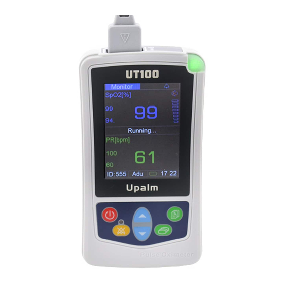
Page 10: Preparation For Use
Chapter 2: General Description CE Mark Indicates separate collection for electrical and electronic equipment. 2.5 Preparation for Use 2.5.1 Getting Acquainted Figure 2.1: Monitor Controls, and Features 1. Sensor Connector The sensor connects here, or an oximetry extension cable can be connected between the monitor and the sensor. 2. SpO Numeric Display A number shows the patient’s SpO value in percent. Dashes (- - -) mean the monitor is not able to calculate the SpO value. 3. Mute icon The mute icon is displayed at the status bar and it has three statuses: Handheld Pulse Oximeter Service Manual... - Page 11 Chapter 2: General Description “ ” this icon means the normal status of alarm sound. “ ” this icon is displayed during temporary 30sec, 60sec, 90sec, 120sec alarm silence. “ ” this icon is displayed steadily during permanent alarm silence. 4. Power Indicator This indicator lights steadily to inform the working status of the monitor. Green means the monitor working normally and red means alarm occurred. 5. Pulse Strength Bar Graph The pulse strength bar graph “sweeps” with the patient’ s pulse beat. The height of the bar graph shows the patient’ s pulse strength. 6. Speaker It provides audible indication of alarm conditions, pulse tone and feedback for key-presses. Ensure the speaker is not covered. 7. Pulse Rate Numeric Display A number shows the patient’ s pulse rate value in beats per minute. Dashes (- - -) mean the monitor is not able to calculate the pulse rate value 8. Information Bar The information bar displays patient’s ID/ type, battery level icon, date/time.
-
Page 12: Power Supply Options
Chapter 2: General Description 14. Silence Indicator This indicator flashes during temporary two-minute alarm silence. The indictor lights steadily during permanent/indefinite alarm silence. 15. Slot for hanging strap 2.5.2 Power Supply Options Batteries. Fresh disposable “AA” alkaline batteries provided approximately 10 hours of operation. Battery capacity maybe reduced in colder temperatures or with excessive power cycling. Figure 2.2: Installing the Batteries To install/replace the batteries: 1. Depress the battery door and remove it downward. 2. Install the negative end of each battery first, compressing the battery terminal spring until the positive terminal clears the positive tab. Press the battery down into place. 3. Place battery door into the slots of the monitor back panel, depress the door tab, and press the door into place. 2-6 Handheld Pulse Oximeter Service Manual... -
Page 13: Power On/Off
Chapter 2: General Description NOTE! If you install disposable batteries, be sure to dispose of them in compliance with your institution’s guidelines and local ordinances. NOTE! The unit will hold data for about one and a half minutes with no battery power. This will insure the safety of trend data during battery replacement. AC Charger. The AC adapter can be used to charge rechargeable batteries and used as a power supply without any battery. Figure 2.2: Connecting AC Charger 2.5.3 Power On/Off To turn the pulse oximeter on, press the power key. “Check ok” and software version will be displayed. An audible tone sounds. The power indicator is briefly illuminated. To turn the pulse oximeter off, press the power key. 2.5.4 Auto Power Off A battery power saving feature allows the pulse oximeter to shut itself off after waiting 5 minutes without detecting any pulsatile activity. Handheld Pulse Oximeter Service Manual... - Page 14 Chapter 2: General Description This page is intentionally left blank. 2-8 Handheld Pulse Oximeter Service Manual...
-
Page 15: Chapter 3: Theory Of Operation
Chapter 3: Theory of Operation Chapter 3: Theory of Operation 3.1 Theory of Operation The pulse oximeter determines %SpO and pulse rate by passing two wavelengths of low intensity light, one red and one infrared, through body tissue to a photodetector. Information about wavelength range can be especially useful to clinicians. Wavelength information for this device can be found in the SpO Specifications section of this manual. Pulse identification is accomplished by using plethysmographic techniques, and oxygen saturation measurements are determined using spectrophotometric oximetry principles. During measurement, the signal strength resulting from each light source depends on the color and thickness of the body tissue, the sensor placement, the intensity of the light sources, and the absorption of the arterial and venous blood (including the time varying effects of the pulse) in the body tissues. Figure 3.1: Theory of Operation 1. Low intensity Red and Infrared LED light sources 2. Detector Oximetry processes these signals, separating the time invariant parameters (tissue thickness, skin color, light intensity, and venous blood) from the time variant parameters (arterial volume and SpO ) to identify the pulses and calculate functional oxygen saturation. Oxygen saturation calculations can... -
Page 16: Circuit Structure Diagram
Chapter 3: Controls and Features WARNING! Under certain clinical conditions, pulse oximeters may display dashes if unable to display SpO and/or pulse rate values. Under these conditions, pulse oximeters may also display erroneous values. These conditions include, but are not limited to: patient motion, low perfusion, cardiac arrhythmias, high or low pulse rates or a combination of the above conditions. Failure of the clinician to recognize the effects of these conditions on pulse oximeter readings may result in patient injury. 3.2 Circuit Structure Diagram Figure 3.2: Circuit Structure Diagram 3.2.1 ON/OFF Switch When the monitor is turned ON (pressing the POWER key for 3 seconds) a positive pulse will make the signal of KEY_POWRE to a low level and the output signal PWR_STB of U4 to a high level. Then the monitor is starting to work. Press the POWER key for 3 seconds again which makes the output signal PWR_STB of U4 to a low level. Then turn the monitor off. 3.2.2 3.3V Digital Supply A switch-mode boost regulator U10 is used to generate the 3.3 volt digital supply (VCC_MCU) from the battery voltage. It is designed to operate over an input voltage range of 2.8V ~ 16.0V. The switch-mode controller U10 includes an Output Voltage Sense, and use the resistor R25, R26to adjust the output voltage. The output voltage can be calculated like this Vout = Vth (R25/R26 + 1). 3-2 Handheld Pulse Oximeter Service Manual... - Page 17 Chapter 3: Theory of Operation 3.2.3 5V SPO2 Power Supply A PWM Controlled Step-Up DC/DC Converters U1 transfers the charging voltage to +5.5V. Output +5V to supply power to the SpO2 board by a highly precise, low noise, positive voltage LDO regulators U9. 3.2.4 Battery Charging Circuit The Ni-MH battery controller IC U12 is used to charge full AA Ni-MH batteries. The highly precision ADC can judge the charging status precisely. 3.2.5 Micro controller The micro controller chosen for the pulse oximeter is the STMicroelectronics group of companies STM32F103VCT6. The core is an ARM 32-bit Cortex™-M3 CPU, capable of running off a 3.3V supply, at up to 72Mhz. Combined with it is ample internal program memory (512 Kbytes of Flash memory) and 64 Kbytes of SRAM. This device also includes a number of integrated peripherals, which make it ideal for this application. There are several timers, and a timing pattern generator, which will be used to generate the front end timing signals; an 8 bit A/D converter, which will be used to monitor the battery status; Two UART serial ports: one is used to communicate with SpO2 board, the other is used to communicate with PC. Two SPI interfaces: one connects the SPI Serial Flash, the other connects the Acceleration. The flexible static memory controller (FSMC) can be configured to interface seamlessly with most graphic LCD controllers. It supports the Intel 8080 and Motorola 6800 modes, and is flexible enough to adapt to specific LCD interfaces. This LCD parallel interface capability makes it easy to build cost-effective graphic applications using LCD modules with embedded controllers or high-performance solutions using external controllers with dedicated acceleration. 3.2.6 Real-time Clock The micro controller integrates RTC function. The real-time clock provides a set of continuously running counters which can be used with suitable software to provide a clock calendar function, and provides an alarm interrupt and a periodic interrupt. It is clocked by a 32.768 kHz external crystal, resonator or oscillator, the internal low power RC oscillator or the high-speed external clock divided by 128. The internal low-speed RC has a typical frequency of 40 kHz. Handheld Pulse Oximeter Service Manual 3-3...
- Page 18 Chapter 3: Controls and Features The RTC can be calibrated using an external 512 Hz output to compensate for any natural quartz deviation. The RTC features a 32-bit programmable counter for long term measurement using the Compare register to generate an alarm. A 20-bit prescaler is used for the time base clock and is by default configured to generate a time base of 1 second from a clock at 32.768 kHz. 3.2.7 Serial wire JTAG debug port (SWJ-DP) The ARM SWJ-DP Interface is embedded, and is a combined JTAG and serial wire debug port that enables either a serial wire debug or a JTAG probe to be connected to the target. The JTAG TMS and TCK pins are shared respectively with SWDIO and SWCLK and a specific sequence on the TMS pin is used to switch between JTAG-DP and SW-DP. 3.2.8 Audio The micro controller’s general-purpose timers used to generate a PWM signal. Use 1.1 Watt Audio Power Amplifier U7 to drive the speaker. 3.2.9 Control Keys Six user operated, control keys are provided (Power, Up, Down, Mode, Silence, Menu). The state of these keys can be read by the software GPIO, which are configured as inputs. The switch lines are normally pulled high, until a key is pressed. 3-4 Handheld Pulse Oximeter Service Manual...
-
Page 19: Chapter 4: Tests
Chapter 4: Tests Chapter 4: Tests 4.1 Function Tests The functional testing verifies overall functional integrity of the monitor and sensor. If the oximeter does not pass these tests, remove from use and contact the manufacturer service department for repair/replacement assistance. This procedure assumes the technician performs each as indicated-leaving the monitor in a know state prior to performing the next step. If the steps are omitted or performed out of order, be sure that the monitor is set to the correct state before continuing. 4.1.1 Equipment Required 1. SpO2 Finger Sensor, Adult. 2. (4) “AA” rechargeable batteries (Half charged) 3. AC Charger. 4. PC. 5. Date analysis software CD. 6. USB Cable. 4.1.2 Test Procedure 1. Visually inspect the monitor and verify that there are no cosmetic defects. 2. Verify all labels are properly placed. 3. Install four AA batteries into the battery compartment. Be careful to follow polarity markings. Close battery door. 4. Turn on the unit by pressing the power button. Verify the following power up sequence occurs: monitor will beep on power on, power indicator will be lit, and the current software revision will be displayed. 5. Adjust the measure mode from the defaulted “Spot-check” to the Handheld Pulse Oximeter Service Manual 4-1... -
Page 20: Checking Data Output
Chapter 4: Tests “Monitoring” mode. Verify that all the keys are usable. 6. Connect the SpO2 finger sensor to the unit and place the sensor over your finger. 7. Verify saturation and pulse rate values are displayed with no error messages displayed. 8. Verify the Battery level Icon is moving when connect the AC charger to the device. 9. Take off the AC charger and remove your finger from the sensor. Verify a “Sensor Offline” message is displayed. 10. Leave the unit running in this state for approximately 5 minutes. Verify after 5 minutes that the unit shuts off automatically. 11. The procedure is complete remove the batteries and disconnect the finger sensor from the unit. 4.1.2 Checking Data Output When you conduct the above fifth step, the measuring data have been store to the device. 1. Install the software. 2. Connect USB cable. 3. Download all the stored data. 4.2 Accuracy Tests The Accuracy Tests verified the performance accuracy of the device. This test is typically performed in conjunction with (after) the Functional Tests. If the monitor does not pass the Accuracy Tests, remove from use and contact the manufacturer service department. This procedure assumes the technician performs each steps as indicated-leaving the monitor in a known state prior to performing the next step. If steps are omitted or performed out of order, be sure that the monitor is set to the correct state before continuing. Handheld Pulse Oximeter Service Manual... -
Page 21: Equipment Required
Chapter 4: Tests 4.2.1 Equipment Required 1. (4) “AA” rechargeable batteries (fully charged) 2. FLUKE Saturation Sensor Simulator, PN: 1170018. 3. SpO2 Finger Sensor, Adult. 4.2.2 Procedure 1. Plug the four fully charged AA batteries into the battery compartment. Be sure to follow the correct polarity. Connect the battery door. 2. Press the power button. Verify the proper power up sequence is displayed. The monitor will beep. And the display shows software revision. 3. Verify the display shows “Sensor no connect”. 4. Turn on the FLUKE and set it to the settings listed in the chart below. Verify the saturation values are in the specified tolerance: FLUKE Settings Monitoring Settings Saturation Attenuation Saturation Pulse Rate 96-100 75±1 88-92 75±1 78-82 75±1 68-72 75±1 5. Connect the FLUKE to the monitor using the SpO2 sensor. Set the ATTENUATION to 3 and SATURATION to 98. 6. Verify the displayed saturation of 96-100 and a pulse of 75. 7. Change the FLUKE power switch to OFF. Verify “Sensor Offline” is displayed. 8. Change the FLUKE power switch to ON. Verify warning message clears and a saturation and pulse value are displayed. 9. Place the finger sensor on your finger. Verify the monitor is displaying a saturation and pulse value with no warning messages. Handheld Pulse Oximeter Service Manual 4-3... -
Page 22: Electronic Tests
Chapter 4: Tests 10. Verify the pulse bar is moving up and down smoothly. 11. Disconnect the finger sensor from the monitor. Verify the monitor delivers two short audio beeps every 10 seconds after the finger sensor is disconnected. Verify the monitor shuts off approximately 5 seconds after the beeping starts. 12. The Accuracy Test is complete. 4.3 Electronic Tests The Electronic Tests verify the calibration and operation of the electronic circuits within the monitor. These tests Do not need to be performed on a regular (preventative) basis. Perform these tests only if the monitor fails to operate as expected of fails the Accuracy Tests or the Functional Tests. The Electronic Tests should be performed only by qualified service personnel. The Electronic Tests require access to the internal components of the monitor. Refer to the Maintenance section for disassembly instructions. CAUTION! The monitor contains static sensitive devices. Be sure to follow proper grounding procedures when handling the internal components to avoid damage from static discharge. The procedure assumes the technician performs each step as indicated- leaving the monitor in a known state prior to performing the next step. If steps are omitted or performed out of order, be sure that the monitor is set to the correct state before continuing. 4.3.1 Equipment Required 1. DC Power Supply, model: PS-305D. PN: 010952932. 2. DC Current Meter 3. Multimeter. 4. 4 “AA” 2200mAh Ni-MH batteries. 5. AC Charger 4.3.2 Procedure 1. Resistance’s Tests: use to test the short circuit on the main board. Switch the Multimeter to . There are total 6 test points: 4-4 Handheld Pulse Oximeter Service Manual... - Page 23 Chapter 4: Tests Location Resistance Opposite of GND on TP1 >10K Opposite of GND on TP2 >500K Opposite of GND on TP3 >10K Opposite of GND on TP4 >50K Opposite of GND on TP10 >2.5 K Opposite of GND on TP13 >500K 2. Voltage Tests: Connect the AC charger to the J6 on the main board, and switch the Multimeter to DC voltage. There are total five test points. Location Nominal Value Voltage Range TP3 3.3V 3.12V-3.48V Hold the SW6 key 3.3V 3.12V-3.48V for 3 second, test TP1 TP3 3.3V 3.12V-3.48V TP2 4.8V-5.2V TP10 4.8V-5.2V 3. Electric Current Test Test the working current of the main board. 1) Connect the DC Current Meter to the BAT+ on the main board. 2) Hold the power key to turn on the monitor and plug the SpO2 sensor. 3) The reading on the DC Current Meter shoud be between 100mA-300mA, normally between 110mA-130mA. If the current is more than 1A, please cut down the power supply at once.
- Page 24 Chapter 4: Tests 2) Series connect the DC Current Meter. 3) Connect the AC charger to J6 of the main board. The reading on the DC Current Meter should be 680mA. It is abnormal if the current is more than 1A. 4. Electric Test is complete. 4-6 Handheld Pulse Oximeter Service Manual...
-
Page 25: Chapter 5: Accessories
Chapter 5: Accessories Chapter 5: Accessories 5.1 Standard Configuration CAT.NO DESCRIPTION QTY UT100B UT100 Handheld Pulse Oximeter Each US10BS Adult Finger SpO Sensor Each 1615 AA size Alkaline Batteries Four 5479 Hanging Strap Each 9230 Operation Manual Each 5.2 Optional Accessories DESCRIPTION QTY CAT.NO 1616 AA size Ni-MH Batteries Four 2319 Hanging Strap Each 1617 AC Charger Each 4210 Reusable sensor, Adult, Finger Each 4211 Reusable sensor, Pediatric, Finger... - Page 26 Chapter 5: Accessories This Page is intentionally left blank! 5-2 Handheld Pulse Oximeter Service Manual...
-
Page 27: Chapter 6: Maintenance And Troubleshooting
Chapter 6: Maintenance and Troubleshooting Chapter 6: Maintenance and Troubleshooting 6.1 Schedule of Maintenance The electronic circuits within the pulse oximeter do not require scheduled calibration or service. The pulse oximeter performs a diagnostic self-test at power-up that checks the internal electronics. If this self-test fails the normal monitoring display will not appear. Remove the oximeter from use and contact qualified service personnel. 6.2 Cleaning and Sterilization To clean and/or sterilize the oximeter and its accessories: 6.2.1 Pulse oximeter Do not immerse the oximeter. Do not sterilize the oximeter. Turn the oximeter off and upplug the external adapter (if used) from the AC power source before cleaning. The oximeter can be cleaned and disinfected with solutions such as a 70% isopropyl alcohol, 2% glutaraldehyde, or 10% bleach solution. Then wipe down with a water dampended clean cloth to rinse. Do before use. 6.2.2 SpO2 Finger Sensor Do not immerse the finger sensor. Do not sterilize the finger sensor. The oximeter can be cleaned and disinfected with solutions such as a 70% isopropyl alcohol, 2% glutaraldehyde, or 10% bleach solution. Then wipe down with a water dampended clean cloth to rinse. Do before use. Make certain that the finger sensor windows are clean and dry before use. After cleaning the finger sensor, perform a Quick Check to verify the sensor is functional. CAUTION! Do not allow isopropyl alcohol or water to enter any of the openings on the monitor. Evidence that liquid has been Handheld Pulse Oximeter Service Manual 6-1... -
Page 28: Storage
Chapter 6: Maintenance and Troubleshooting allowed to enter the monitor voids the warranty. 6.3 Storage WARNING! To ensure accurate performance and prevent device failure, do not subject the UT100 to extreme moisture such as direct exposure to rain. Such exposure may cause inaccurate performance or device failure. Whenever possible, the monitor should be stored at room temperature in a dry environment. If it is necessary to store the monitor for an extended period of time, the unit should be packed in its original shipping container. Storing the monitor for a long period of time may degrade the battery capacity. Batteries should be removed from the monitor before storing. Storage specifications are as follows: Temperature: -20oC to +55oC Relative Humidity: 10% to 95% (noncondensing) 6.4 Assembly Exchanges Disassembly should be performed by qualified service personnel only. 6.4.1 Internal Assemblies 1. Ensure that the monitor is OFF. Remove the battery compartment cover and place aside, remove the batteries. 2. Turn the monitor over and remove the six screws from the back cover 3. Carefully lift the back and front cover from the monitor. 4. Remove the two braces of LCD display on the Main board by a tweezers and take off the LCD display by welding the FPC. 5. The separate assemblies of the monitor can now be accessed. 6-2 Handheld Pulse Oximeter Service Manual... -
Page 29: Reassembling The Oximeter
Chapter 6: Maintenance and Troubleshooting Figure 6.1: Exploded Structure Drawing 6.4.2 Reassembling the oximeter 1. Reconnect the LCD display and main board by welding the FPC. 2. Reinstall the two braces of LCD display by a tweezers. 3. Seat the display/main board assembly into the back cover. 4. Replace the top cover and the six screws, batteries and battery compartment cover. 6.3 Troubleshooting Table 6.1: PROBLEM POSSIBLE CAUSE CORRECTIVE ACTION •Patient cable or sensor •Check sensor connections is disconnected from the to the patient cable and to oximeter. the oximeter. No pulse shown on •Sensor is incorrectly •Reposition the sensor. the bargraph. positioned on the patient. •Reposition the sensor. •Poor patient perfusion. - Page 30 Chapter 6: Maintenance and Troubleshooting Pulse rate is erratic, •Sensor incorrectly •Reposition the sensor. intermittent, or positioned. incorrect. •Patient motion •Patient must remain still to obtain an accurate measurement. SpO2 value is •Poor patient perfusion. •Reposition the sensor. erratic, intermittent, •Patient motion. •Patient must remain still to or incorrect. obtain an accurate measurement. • Defective sensor or •Try a new sensor or contact No PR and SpO2 patient cable or monitor. your authorized repair values. center for help. •Batteries incorrectly • Reposition batteries installed. correctly. Battery Abnormal •There are no batteries. •Equip with oximeter with batteries. •Batteries weak. •Replace the batteries. The oximeter •Batteries not installed •Ensure the batteries are doesn’t turn on.
- Page 31 Chapter 6: Maintenance and Troubleshooting Overload of the charging Test the resistance of R8. voltage and working current. Add tin to U13, U12, Q5 and Q8. Can not work with AC charger Welding the CPU again. but batteries. The resistance on TP1 or TP3 This is problem is caused by the is short circuit and no short circuit of CPU’s Pin. resistance. Welding the Pin on the welding table again.
- Page 32 Chapter 6: Maintenance and Troubleshooting This Page is intentionally left blank! 6-6 Handheld Pulse Oximeter Service Manual...
-
Page 33: Chapter 7: Specification
Chapter 7: Specifications Chapter 7: Specification 7.1 Equipment Classification Internally Powered Type of Protection Against Electric shock: Continuous Mode of operation: IPX1, drip proof Degree of Protection Against ingress of Liquids: Handheld Degree of Mobility: Type BF Degree of Protection Against Electric Shock: EN60601-1:1990 Safety Requirements: 7.2 SpO Range: 0-100% Accuracy: ±2 at 70 - 100% <70%, undefined Resolution: Display Response: The display is to functional saturation. The pulse strength bar graph is not proportional to pulse volume. 7.3 Pulse Rate Range: 30-250bpm Accuracy: ±2 at 30 – 250bpm Resolution: 1bpm 7.4 Default Settings of Alarms Limits High Alarm Limits Low Alarm Limits Adult Pediatric... -
Page 34: Battery Life
Chapter 7: Specifications 7.6 Battery Life Alkaline Cells: 20 hours 7.7 Dimensions Width: 75mm (2.95 inches) Height: 135mm (5.31 inches) Depth: 28mm (1.10 inches) Weight: 258grams (9.10 ounces) with batteries 7.8 Environmental Specification 0 to 45℃ Operating Temp.: -20 to +55℃ Storage Temp.: -40 to +55℃ Shipping Temp.: 30 to 95% (operating) Relative Humidity: 10 to 95% (storage) 0 to 95% (shipping) 7-2 Handheld Pulse Oximeter Service Manual... -
Page 35: Chapter 8: Drawings
Chapter 8: Drawings Chapter 8: Drawings No. Description Exploded Structure Drawing Schematic, Main Board Schematic, Power Schematic, Battery Charger Schematic, Acceleration Schematic, Key Handheld Pulse Oximeter Service Manual 8-1... - Page 36 Chapter 8: Drawings This page is intentionally left blank! 8-2 Handheld Pulse Oximeter Service Manual...
- Page 37 floor, NO.39, Jinqiao Road, Zhangjiawan, Shapingba District, Chongqing, China Phone (+86)23-6172-8390 Fax (+86)23-6172-8391 E-mail service@chinautech.com Web site www.chinautech.com...
Need help?
Do you have a question about the UT100 and is the answer not in the manual?
Questions and answers