Table of Contents
Advertisement
Quick Links
Advertisement
Table of Contents

Related Manuals for RAB EVC48


Summary of Contents for RAB EVC48
- Page 1 Welcome EVC48 Smart Charging Station INSTALL ATION INSTRUC TIONS...
-
Page 2: Safety Instructions
Safety Instructions Read all Important Safety Instructions as well as charging instructions in your vehicle owner’s manual before attempting to charge your electric vehicle. Failure to do so can result in death or severe injury. Save this user manual for future reference. There are many safety features built into the charger. - Page 3 • Do not forcefully pull the charging cable, damage it with sharp objects, or place fingers or insert foreign objects into any part of the charging connector. • Risk of explosion. This device has arcing or sparking parts that should not be exposed to flammable vapors.
- Page 4 Contents AC charger Wall-mount bracket (with charging cable) and inlet box Expansion M5 self-tapping Torx/ T30 M5 screw × 5 screw × 4 screws × 4 L-wrench Installation Product RFID card × 2 instructions Certification...
-
Page 5: Tools And Materials Required
Tools and Materials Required Tools required before installing the charger onto the Wall-Mount Bracket are: • Wire stripper • Crimpers for ring terminals • Phillips screwdriver for M4 – M6 1-3/8 inch or 34 mm drill bit • Voltmeter or digital multimeter (for measuring AC voltage at the installation site) •... - Page 6 EVC48 Installation Requirements To select the best location and position to install the wall-mount unit, you should first determine the parking position of the vehicle to ensure the charging connector can be easily inserted into the vehicle charging inlet. The wall-mount unit should be located: •...
-
Page 7: Setup And Installation
Setup & Installation Installation of the wall-mounted metal plate Take out the wall-mounted metal plate and locate all the installation holes. Use as a template to mark on the wall with a pencil or any tool, and insert 4 sets of expansion bolts (M5 X 40mm) into the wall, as shown in the figure. Install the wall-mounted metal plate on the cement wall. - Page 8 Setup & Installation (cont’ d ) Installation of the wire box First, remove the waterproof cover at the inlet end marked as “AC In”. Then, install the accessory “1-inch liquidtight flexible metal conduit” at the inlet of the power cord, and attach the wire box to the wall-mounted metal plate with screws.
- Page 9 Setup & Installation (cont’ d ) Installation and setting of the network cable Remove the waterproof plug from the Internet interface at the bottom left of the wire box. Feed the network cable into the wire box through the network cable entrance.
-
Page 10: Installation Of The Charger
Setup & Installation (cont’ d ) Installation of the SIM card Only available for 4G models Note: Confirm that the SIM card password has been removed prior to installation, as the charger post does not support SIM cards with passwords. Installation of the charger First, connect the network cable to the charger. - Page 11 Setup & Installation (cont’ d ) Next, move the charger equipment in a horizontal direction, so that the AC connector of the equipment can be inserted into the conductive spring plate of the wire box. Meanwhile, apply pressure to the equipment, so that the three screw holes of the equipment align with the three holes of the wall- mounted metal plate.
- Page 12 Setup & Installation (cont’ d ) Power on charger to provision charger settings For setting instructions refer to Charger Standard Setting on page 24. electric box Power off and unplug the connection Power off the machine and remove the network cable once setting is completed.
- Page 13 Setup & Installation (cont’ d ) Remove the three screws on the charger in the order bottom (1) – right (2) – left (3). Pull the network cable out of the wire box, then remove the network cable. Install the waterproof plug, then re-install the charger and wire box.
- Page 14 Setup & Installation (cont’ d ) Let the three screw holes of the equipment align with the three holes of the wall-mounted metal plate, then tighten with the M6 plum screws in the order left – right – bottom, with a tightening torque of 30 kg-cm.
- Page 15 Setup & Installation (cont’ d ) Installation of charging gun wiring Wrap the charging gun wire around the equipment (about two turns), so that the charging gun wire will not hang down to the ground. Once the wrapping is done, insert the charging gun head into the hole of the charging gun base on the front panel of the machine to complete the installation of the equipment.
-
Page 16: Safety Requirements
Setup & Installation (cont’ d ) Safety requirements • Read this user manual thoroughly and make sure to review all local building and electrical codes before installing the AC charger. A qualified technician should install the AC charger according to the user manual and local safety regulations. •... - Page 17 Setup & Installation (cont’ d ) Power grid connection and grounding type • This AC charger supports different power grid connections and grounding types. You can configure through the setting dip switch. Setting methods are shown below. • Before setting the dip switch, make sure the input power is turned OFF. •...
-
Page 18: Maximum Output Current
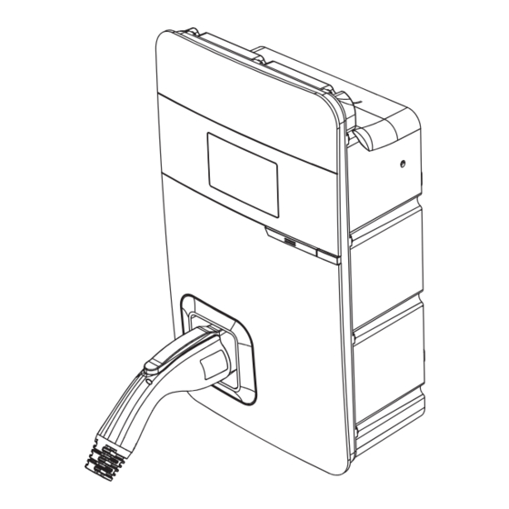
Setup & Installation (cont’ d ) Maximum output current This AC charger can support different maximum output current through the setting rotary switch. Setting methods are shown below. • Before setting the rotary switch, make sure the input power is turned OFF. •... - Page 19 Interface 5" LCD screen LED light indication SAE J1772 AC charging connector Wall-mount bracket with power box AC power inlet Charging cable inlet...
- Page 20 Interface (cont’ d ) Bottom Case and Wire Box Blade male connector Power and grounding setting For 4G SIM card Network and setting port Ethernet inlet AC inlet Blade female connector Ethernet inlet hole AC inlet hole...
- Page 21 Status Description of the Charger Indication Lights Work Status Blue Green Initial Constantly bright (white) Idle Backend connected Sleep – Breath – Constantly Idle Backend connected – – bright Idle Backend disconnected Sleep – Breathing (yellow) Idle Backend disconnected – Constantly bright (yellow) Authorize RFID authorization Pass Flicker 3 sec...
- Page 22 Screen Instructions Status Bar Ethernet connected Ethernet Status code with internet not connected Ethernet connected without internet WiFi connected WiFi not with internet connected WiFi connected without internet 4G connected 4G not with internet connected 4G connected without internet Backend online Backend offline Status Code Table Status Code...
- Page 23 Screen Instructions (cont’ d ) Status Code Table (cont’d) For latest status code, visit our website. Status Code Description 012241 WiFi module communication fail 3G/4G module communication fail 012242 012243 RFID module communication fail 012254 Fail to create share memory 012255 CSU initialization failed 012256...
-
Page 24: Time Setting
Charger Standard Setting Time setting Automatic setting The time will be adjusted automatically when the charger connects to the internet. Time server: • time.windows.com • cn.ntp.org.cn • tock.stdtime.gov.tw Note: Firewall and network environment may influence the time server connection. Connect the RJ45 cable to the charger. Connect the RJ45 cable to the notebook. - Page 25 Charger Standard Setting (cont’ d ) Open a browser and enter IP address 192.168.1.10 192.168.1.10 to log into the setup page. login https://192.168.1.10 Use the following credentials to log in. Account admin • Account: admin Password 1231231238 • Password: 1231231238 192.168.1.10 UPGRADE OTHER LANGUAGE Select “SET”...
-
Page 26: Wifi Setting
Charger Standard Setting (cont’ d ) WiFi setting Tools required before setting • Notebook with RJ45 interface • One RJ45 cable connector is male to male Select “SET” at the top of the webpage to enter the settings page. Select “Network” to enter the network settings page. - Page 27 Charger Standard Setting (cont’ d ) 4G setup For the optional 4G Edition Note: Confirm that the SIM card password has been removed prior to installation, as the charger post does not support SIM cards with passwords. Select “SET” at the top of the webpage to 192.168.1.10 enter the settings page.
-
Page 28: Checking Signal Strength
Charger Standard Setting (cont’ d ) Checking signal strength Re-checking WiFi and 4G signal strength on power-up. After restarting the charger, check the connection signal strength. The RSSI (Received Signal Strength Indication) should be higher than -65dBm. If the value is lower, you may experience a weak WiFi signal connection or even disconnection. - Page 29 Charger Standard Setting (cont’ d ) Select the WiFi and 3G/4G module to 192.168.1.10 enter the setting. Network Network Status Ethernet WiFi 3G/4G 192.168.1.10 Network Wi-Fi Mode SSID Confirm signal strength. RSSI -65dbm WiFi Version DHCP Client Make sure the WiFi strength is higher than -65dbm.
- Page 30 Local Load Balance Mode only) OFFLINE • When selecting Local Load Balance Mode,there must be a minimum of 2 and a maximum of 4 chargers of the same model, and no more than 5 including the master. • This mode is only available when there is no internet connection. •...
- Page 31 Local Load Balance Mode only) OFFLINE (cont’ d ) Usage example: LAN containing three devices Maximum output of devices: 48A Number of devices: 3 Example 1 If there is only one charging device in use in the charging LAN, the master will authorize maximum current output to the device in use, including if only the master is in use.
-
Page 32: Operating Procedure
Operating Procedure Select master If the charger still has the default factory settings, it can be used as the master without need for setup, but if other settings have already been completed on the charger, first refer to Master Setup below. Master Slave Slave... -
Page 33: Master Setup
Operating Procedure (cont’ d ) Master setup The rotary switch needs to be set to the default value B. Important! If the local mains power system does not support 48A, adjust according to the size of the local power load. The master will output current according to the set power level. - Page 34 Operating Procedure (cont’ d ) Master webpage WiFi setup Open a browser and enter the 192.168.1.10 IP address 192.168.1.10 to log into login https://192.168.1.10 the setup page. Use the following Account admin credentials to log in. Password 1231231238 • Account: admin •...
- Page 35 Operating Procedure (cont’ d ) Master webpage WiFi setup (cont’d) Select “SET” at the top of the 192.168.1.10 webpage to enter the settings page. UPGRADE OTHER LANGUAGE Select “Backend” to enter the System System network settings page. Charging Network Backend Select OCPP and set the Local load 192.168.1.10 balance to enable.
- Page 36 Operating Procedure (cont’ d ) Confirm model name and serial number of master Check the model name and S/N information on the model label located on the side of the device. When setting up connection on slave devices, the master device information will be used as the account password. Example: Slave SSID: AXLU111001D1P1D1616A001A1 Slave password: D1616A001A1AXLU111001D1P1...
- Page 37 Operating Procedure (cont’ d ) Select slave • Make sure that the number of slaves does not exceed 4 • There must be no walls or obstructions that affect communication between master and slaves • It is recommended that the master be located in the middle of all the slaves, to ensure the best signal reception Master Slave...
- Page 38 Operating Procedure (cont’ d ) Set rotary switch on slave Turn the charger around so that the rear side is facing you. Find the rotary switch and rotate it to the F position. Rotary switch...
- Page 39 Operating Procedure (cont’ d ) Set slaves to connect to master This setup procedure connects the slaves to the master to form a local area network (LAN). Open a browser and enter the 192.168.1.10 IP address 192.168.1.10 to log into login https://192.168.1.10 the setup page.
- Page 40 Operating Procedure (cont’ d ) Set slaves to connect to master (cont’d) Select “SET” at the top of the 192.168.1.10 webpage to enter the settings page. UPGRADE OTHER LANGUAGE Select “Backend” to enter the System System network settings page. Charging Network Backend Select OCPP and set the Local load...
-
Page 41: Setup Complete
Operating Procedure (cont’ d ) Check master and slave connection status Make sure that the WiFi strength is higher than -65dBm. 192.168.1.10 Network Wi-Fi Mode SSID Password RSSI -65dbm DHCP Client Wi-Fi Setup complete Master Slave Slave Slave Slave... - Page 42 Operating Instructions Standby – Green Light Wait to see the standby light show STEADY GREEN. When the charger is not operated for 120 seconds, it will enter sleep mode. When the machine is a connected to the backend, the standby light remains GREEN, and it becomes SLEEP GREEN when the machine enters sleep mode.
- Page 43 Operating Instructions (cont’ d ) Waiting for charging – Blue Light After the vehicle connector is connected to the vehicle inlet, the CHARGE light is constantly lit. Charging – Blue Light flashing The CHARGE light flashes while charging. Fault – Red Light The red light is lit when a fault occurs.
-
Page 44: Error And Warning Messages
Error and Warning Messages Status Remark One flash followed by a Measure the input voltage to see if it is higher Input OVP 3-sec pause than 275V Two flashes followed by a Measure the input voltage to see if it is lower Input UVP 3-sec pause than 160V... - Page 45 Error and Warning Messages (cont’ d ) Verify that the Wall Connector is properly grounded. The ground connection must be bonded in the upstream power supply for proper operation. Check all physical connections, including the wire box terminals, electrical panel(s), and wire box. In residential power supplies, check the bond between ground and neutral at the main panel.
-
Page 46: Maintenance And Repair
Maintenance and Repair Daily Maintenance Keep the charger clean and install it in a clean area with low humidity. Do not install it in an environment near the sea, with high levels of oil, humidity or dust. • Avoid moisture or water in the charger. If water or excess moisture gets into the charger, immediately power off the charger to avoid immediate danger. -
Page 47: Fcc Information
20 cm from all persons and must not be co-located or operating in conjunction with any other antenna or transmitter. CAUTION: Changes or modifications to this equipment not expressly approved by RAB Lighting may void the user’s authority to operate this equipment. - Page 48 Technical Support: ( 888 ) 728-4094 © 2023 RAB Lighting Inc.
Need help?
Do you have a question about the EVC48 and is the answer not in the manual?
Questions and answers