Advertisement
Quick Links
Maximum load current [A]
TECHNICAL DATA
External parts of the switch are made of non-combustible high impact ABS
plastic. Operating mechanism of the switch is equipped with screw contacts.
Screws with combination heads for use with a standard or a cross screwdriver.
Maximum supply voltage [V]
Maximum load current [A]
Cable cross section [mm
]
2
Temperature range [°C]
Humidity range [%]
Service life
Electrical protection class
Weight [g]
OVERALL AND CONNECTING DIMENSIONS
80.5
1
ON
OFF
2
INSTALLATION
MOUNTING AND CONNECTION OF THE ELECTRICAL
EQUIPMENT SHOULD BE PERFORMED ONLY WHEN THE POWER
ALL THE OPERATIONS WITH THE SPEED SWITCH MUST BE
PERFORMED BY QUALIFIED ELECTRICIANS WITH A WORK
PERMIT FOR ELECTRIC OPERATIONS AND AFTER CAREFUL
READING OF THE USER'S MANUAL.
ANY INTERNAL CONNECTION MODIFICATIONS ARE NOT
ALLOWED AND RESULT IN WARRANTY LOSS.
CAUTION!
Makes sure that the switch is intact. Do not use damaged speed switches.
Do not mount the speed switch onto an uneven surface.
While tightening the self-tapping screws do not apply excessive force to
prevent speed controller casing deformation.
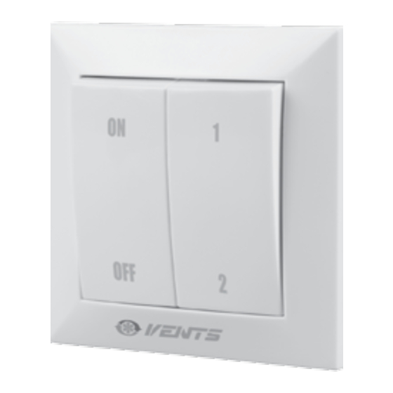
Speed switch P2-10
PURPOSE
Applied in ventilation systems for turning
the fans on/off and speed switch of multi-
speed fan motors.
DELIVERY SET
Speed switch
1 pc.
User's manual
1 pc.
Packing box
1 pc.
P2-10
Speed switch
Two speeds
250
10
from 0.35 up to 0.75
from -10 up to +45
5 - 80 (no condensation)
1 000 000 switching operations
IP40
98
52
SUPPLY IS SWITCHED OFF.
The speed switch is mounted into the mounting box using screws or fixing
lugs. A mounting box and fasteners are not included in the delivery set.
Mounting of the speed switch:
1. Make a niche in the wall for mounting of the speed switch, route the
necessary wires and cables to the mounting place. Insert the mounting box
in the niche.
2. Use a screwdriver to carefully remove the buttons.
3. Unlatch and remove the frame of the control unit.
4. Install the speed switch into the niche in the wall.
5. Install the frame and the buttons in the reverse order.
CONNECTION
CAUTION!
To avoid damaging the speed switch, prevent it from being
overloaded. The maximum permissible load current is shown in the «Technical
data» section. Protect the speed switch casing from ingress of foreign objects.
Check the contact arrangement before connecting the unit.
Connect the speed switch according to the wiring diagram:
L 1
L 2
N
CONTROL
The two speed fan can be manually switched ON to one of the two required
speeds or switched OFF using the speed switch buttons.
ON
OFF
N
L
L 2
L 1
L 3
First
1
ON
speed
Second
OFF
2
speed
Advertisement

Related Manuals for Vents P2-10


Summary of Contents for Vents P2-10
- Page 1 The speed switch is mounted into the mounting box using screws or fixing lugs. A mounting box and fasteners are not included in the delivery set. Speed switch P2-10 Mounting of the speed switch: 1. Make a niche in the wall for mounting of the speed switch, route the necessary wires and cables to the mounting place.
- Page 2 Violation of the unit transportation regulations by the user. • Violation of the unit storage regulations by the user. • Wrongful actions against the unit committed by third parties. SPEED SWITCH P2-10 is recognized as serviceable. Quality Inspector’s Stamp Manufacture Date __________________________________________ Seller...
Need help?
Do you have a question about the P2-10 and is the answer not in the manual?
Questions and answers