Table of Contents
Advertisement
Quick Links
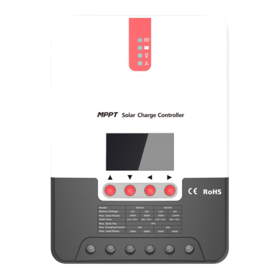
ML Maximum Power Point Tracking (MPPT) Series
Solar Charge and Discharge Controller User Manual
Model
Battery voltage
Max. solar panel voltage
Charging current
Discharging current
Dear users,
Thank you for choosing our product!
Safety Instructions
ML2420—ML2430—ML2440
ML2420
20A
ML2430
12V/ 24V
100V (25°C), 90V (-25°C)
30A
20A
ML2440
40A
Advertisement
Table of Contents

Summary of Contents for WATTUNEED ML Series
- Page 1 ML Maximum Power Point Tracking (MPPT) Series ML2420—ML2430—ML2440 Solar Charge and Discharge Controller User Manual Model ML2420 ML2430 ML2440 Battery voltage 12V/ 24V Max. solar panel voltage 100V (25°C), 90V (-25°C) Charging current Discharging current Dear users, Thank you for choosing our product! Safety Instructions...
-
Page 2: Table Of Contents
1. As this controller deals with voltages that exceed the top limit for human safety, do not operate it before reading this manual carefully and completing safety operation training. 2. The controller has no internal components that need maintenance or service, thus do not attempt to disassemble or repair the controller. -
Page 3: Product Features
battery in maximum power. It's designed to be used in off-grid solar photovoltaic systems to coordinate operation of the solar panel, battery and load, functioning as the core control unit in off-grid photovoltaic systems. This product features an LCD screen which can dynamically display the operating status, operating parameters, controller logs, control parameters, etc. -
Page 4: Exterior And Interfaces
of various occasions. The controller employs a built-in over-temperature protection mechanism. When ◆ temperature surpasses the set value, the charging current will decline in linear proportion to the temperature so as to curb the temperature rise of the controller, effectively keeping the controller from being damaged by overheat. Featuring a temperature compensation function, the controller can automatically adjust ◆... -
Page 5: Introduction To Maximum Power Point Tracking Technology
Item Item Charging indicator Battery "+" interface Battery indicator Battery "-" interface Load indicator Load "+" interface Abnormality indicator Load "-" interface LCD screen External temperature sampling interface Operating keys RS232 communication interface Installation hole Solar panel "+" interface Solar panel "-" interface 1.4 Introduction to Maximum Power Point Tracking Technology Maximum Power Point Tracking (MPPT) is an advanced charging technology that... -
Page 6: Charging Stages Introduction
settings according to the environmental conditions in real time, so as to always keep the system close to the max. operating point. The whole process is entirely automatic without the need of human intervention. I(A) 光 照 降 低,电 流 减小 U(V) 光... - Page 7 sustaining charging and floating charging. The charging curve is as shown below: Fig. 1-5 Battery charging stages diagram a) Fast charging At the fast charging stage, as the battery voltage has not reached the set value of full voltage (i.e. equalizing/ boost When the voltage) yet, the controller will perform MPPT charging on the battery with the maximum solar power.
-
Page 8: Product Installation
Note: risk of equipment damage! Overcharge or too much gas generated may damage battery plates and cause active material on the battery plates to scale off. Equalizing charging to an excessively high level or for too long a period may cause damage. Read carefully the actual requirements of the battery deployed in the system. -
Page 9: Wiring Specifications
may further melt the wire's insulation layer and burn surrounding materials, and even cause a fire, therefore make sure all connections are tightened securely. Wires had better be fixed properly with ties, and when needs arise to move things, avoid wire swaying so as to keep connections from loosening. - Page 10 Step 1: choose the installation site Do not install the controller at a place that is subject to direct sunlight, high temperature or water intrusion, and make sure the ambient environment is well ventilated. Step 2: first place the installation guide plate at a proper position, use a marking pen to mark the mounting points, then drill 4 mounting holes at the 4 marked points, and fit screws in.
- Page 11 Step 4: wire First remove the two screws on the controller, and then begin wiring operation. In order to guarantee installation safety, we recommend the following wiring order; however, you can choose not to follow this order and no damage will be incurred to the controller. Connecting to external temperature sampling interface Connecting communication cable Connecting power cable...
- Page 12 "+" and then "-". Power on Tips: ML Series controllers can only be started through wiring of the battery terminals, but ML-LI Series controllers can be started by switching on the power supply of the photovoltaic array. The latter case applies to starting the controller and activating the lithium battery when the lithium battery BMS is in protection state and therefore can't output power.
-
Page 13: Product Operation And Display
3. Product Operation and Display 3.1 LED Indicators Indicating the controller's current charging ---PV array indicator mode. ---BAT indicator Indicating the battery's current state. ---LOAD indicator Indicating the loads' On/ Off and state. Indicating whether the controller is ---ERROR indicator functioning normally. -
Page 14: Key Operations
(a cycle of 2s with on and off discharged each lasting for 1s) Quick flashing Battery over-voltage (a cycle of 0.2s with on and off each lasting for 0.1s) LOAD indicator: Indicator state Battery state Load turned off Quick flashing Load overloaded/ (a cycle of 0.2s with on and off short-circuited... -
Page 15: Lcd Startup And Main Interface
3.3 LCD Startup and Main Interface 3.3.1 Startup interface During startup, the 4 indicators will first flash successively, and after self- inspection, the LCD screen starts and displays the battery's voltage level which will be either a fixed voltage selected by the user or a voltage automatically recognized. -
Page 16: Load Mode Setting Interface
3.4 Load Mode Setting Interface 3.4.1 Load modes introduction This controller has 5 load operating modes which will be described below: Mode Descriptions When no sunlight is present, the solar panel voltage is lower than the light control on Sole light control voltage, and after a time delay, the controller will switch on the load;... -
Page 17: System Parameter Settings
Users can adjust the load mode as needed on their own, and the default mode is debugging mode (see "load modes introduction"). The method for adjusting load modes is as follows: 3.4.3 Manual load on/ off page Manual operation is effective only when the load mode is manual mode (15), and tap the Set key to switch on/ off the load under any main interface. -
Page 18: Product Protection Function And System Maintenance
Floating charging FLOAT CHG 9.0 to 17.0V 13.8V voltage Over-discharge LOW VOL RECT 9.0 to 17.0V 12.6V recovery voltage Over-discharge LOW VOL DISC 9.0 to 17.0V 11.0V voltage Table 3 4. Product Protection Function and System Maintenance 4.1 Protection Functions Waterproof ... -
Page 19: System Maintenance
power or halt charging. See the following diagram: Chg-P :/% 100% 67 68 69 70 71 72 73 74 75 76 77 78 79 Tem-MOS :/℃ Fig. 4-1 4.2 System Maintenance In order to always keep the controller's performance at its optimum level, we ◆... -
Page 20: Product Specification Parameters
Battery under- ERROR indicator voltage warning steady on LOAD indicator flashing quickly Load short circuit ERROR indicator steady on LOAD indicator flashing quickly Load overloaded ERROR indicator steady on Over-temperature ERROR indicator inside controller steady on Photovoltaic ERROR indicator component steady on overloaded Photovoltaic... -
Page 21: Battery Type Default Parameters (Parameters Set In Monitor Software)
Weight 1.4kg Communication method RS232 Altitude ≤ 3000m Product dimensions 210*151*59.5mm 238*173*72.5 238*173*72.5 5.2 Battery Type Default Parameters (parameters set in monitor software) Parameters cross-reference table for different types of batteries Sealed lead- Gel lead-acid Open lead-acid User (self- Voltage to set acid battery battery battery... -
Page 22: Conversion Efficiency Curve
voltage; Under-voltage warning return voltage > Under-voltage warning voltage ≥ Discharging limit voltage; Boost return voltage > Low-voltage cut-off return voltage 6. Conversion Efficiency Curve 6.1 12V System Conversion Efficiency 6.1 24V System Conversion Efficiency... -
Page 23: Product Dimensions
7. Product Dimensions...
Need help?
Do you have a question about the ML Series and is the answer not in the manual?
Questions and answers