
Related Manuals for Woodward easYgen LS-6XT

Summary of Contents for Woodward easYgen LS-6XT
- Page 1 easYgen|LS-6XT Technical Manual Circuit Breaker Control easYgen LS-612XT-P1 Release 2.10-1 Document ID: B37914, Revision: B - Build 50478...
- Page 2 This is no translation but the original Technical Manual in English. Designed in Germany. Woodward GmbH Handwerkstr. 29 70565 Stuttgart Germany Telephone: +49 (0) 711 789 54‑510 Fax: +49 (0) 711 789 54‑101 E-mail: stgt-info@woodward.com Internet: http://www.woodward.com © 2020 Woodward GmbH easYgen|LS-6XT B37914...
- Page 3 The LS-6XT Series are circuit breaker control units for engine-generator system management applications. The control units can be used stand-alone or in applications in combination with Woodward easYgen-3400/3500XT genset control units and/or easYgen | GC-3400XT . For a listing of all available application modes please refer to ╚═▷ “6 Application Field”.
- Page 4 Brief Overview QR Code To get access to the complete product documentation, scan this QR code or use the following link: ══▷ http://wwdmanuals.com/easygenlls-6xt. Naming convention To keep the simplicity in reading easYgen | LS-6XT is referred as "LS-6XT" easYgen|LS-6XT B37914...
-
Page 5: Table Of Contents
Table of Contents Table of Contents General Information ............17█... - Page 6 Table of Contents 3.2.6.2 Breaker mode CBA/CBB ............62█...
- Page 7 Table of Contents 4.1.5.9 LogicsManager ..............100█...
- Page 8 Table of Contents 4.4.2 Configure Breakers ............. . 170█...
- Page 9 Table of Contents 4.5.3.1 ................259█...
- Page 10 Table of Contents 4.6.3.2 External Active Power ............307█...
- Page 11 Table of Contents 6.1.1 Introduction ..............363█...
- Page 12 Table of Contents CANopen Application ............. 457█...
- Page 13 Table of Contents 8.1.2 Ambient Variables ............. . . 483█...
- Page 14 Table of Contents 9.4.2.5 Group 07: System A related alarms ..........578█...
- Page 15 Table of Contents 9.4.5 Factory Settings ..............617█...
- Page 16 Table of Contents 9.6.2 Event Message ..............640█...
-
Page 17: General Information
1 General Information 1.1 About This Manual General Information About This Manual 1.1.1 Revision History Rev. Date Editor Changes in chronological descending order 2020-09 NEW Software Revision Release 2.10-1 or higher Corrections/Repairs • Installation / Power Measuring Changed sign of the power measurement according to the CT connection of the easYgen platform. -
Page 18: Depiction Of Notes And Instructions
1 General Information 1.2 Depiction Of Notes And Instructions Depiction Of Notes And Instructions Safety instructions Safety instructions are marked with symbols in these instructions. The safety instructions are always introduced by signal words that express the extent of the danger. DANGER! This combination of symbol and signal word indicates an immediately-dangerous situation that could cause death or severe injuries if not avoided. -
Page 19: Copyright And Disclaimer
All information and instructions in this manual have been provided under due consideration of applicable guidelines and regulations, the current and known state of the art, as well as our many years of in-house experience. Woodward assumes no liability for any damages due to: •... -
Page 20: Service And Warranty
In addition, our employees are constantly interested in new information and experiences that arise from usage and could be valuable for the improvement of our products. Warranty terms Please enquire about the terms of warranty from your nearest Woodward representative. For our contact search webpage please go to: ══▷ http://www.woodward.com/ Directory.aspx... -
Page 21: General Safety Notes
1 General Information 1.3.2 General Safety Notes The qualified electrician has been specially trained for the work environment in which he is active and is familiar with all relevant standards and regulations. • User The user operates the device within the limits of its intended use, without additional previous knowledge but according to the instructions and safety notes in this manual. - Page 22 Device implemented self test this Woodward device has a self test check implemented. Permanently under control are: • processor function and • supply voltage. The internal signal "self check" is aligned in series with the inverse signal »Ready for op.
- Page 23 Unit includes a lithium backup battery for Real Time Clock. Field replacement of the battery is not allowed. In case of battery replacement please contact your Woodward service partner. Electrostatic discharge Before working with terminals please read the following instructions.
-
Page 24: Protective Equipment And Tools
For additional information on how to prevent damage to electronic components caused by improper handling, read and observe the precautions in: • "Woodward manual 82715, Guide for Handling and Protection of Electronic Controls, Printed Circuit Boards, and Modules". 1.3.3... - Page 25 1 General Information 1.3.3 Protective Equipment And Tools • Note the required torque range individually specified in the tasks listed in this manual. B37914 easYgen|LS-6XT...
-
Page 26: System Overview
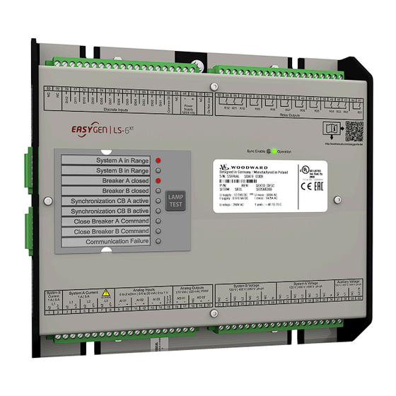
2 System Overview 2.1 Display And Status Indicators System Overview Display And Status Indicators HMI and ToolKit are aligned for the same sequence and structure of functions and parameters. Restrictions Full access to all parameters and settings with ToolKit only! LEDs Indicate State of Metal Housing Variant The LS-612XT-P1 variant is coming with two DUO LEDs red/green/orange (orange = red/ green simultaneously) and nine LEDs red. -
Page 27: Application Layer Overview
2 System Overview 2.2 Application Layer Overview ◦ Red: critical alarm (alarm class C, D, E or F) is active ◦ Toggling green/off: the "System update" procedure is active LEDs closed to the Paper strip • System A in range (pre-configured) •... -
Page 28: Operation Modes
2 System Overview 2.3 Operation Modes Operation Modes The LS-6XT offers two operation modes: • AUTO • MANUAL (MAN) • ... and an internal (non) operating phase during the start-up of the device. For more information about the operation modes please see ╚═▷... - Page 29 2 System Overview 2.4 Synch. Check Functionality • Voltage, • Frequency and • Phase angle. The command variable Sync Condition 02.29) is true, if the "System A is okay", "System B is okay" and the phase matching synchronisation conditions are met according to: The following parameters •...
-
Page 30: Installation
3 Installation 3.1 Mount Unit (Sheet Metal Housing) Installation Mount Unit (Sheet Metal Housing) Dimensions 227mm 250mm 50mm Fig. 3: Sheet metal housing - dimensions Mounting into a cabinet ⚙ ᐳ • Special tool: Torque screwdriver Proceed as follows to install the unit using the screw kit: easYgen|LS-6XT B37914... - Page 31 3 Installation 3.1 Mount Unit (Sheet Metal Housing) 1. ▷ Fig. 4: Sheet metal housing - drill plan Drill the holes according to the dimensions in ╚═▷ Fig. 4 (dimensions shown in mm). Ensure sufficient clearance for access to the terminals (top and bottom) and connectors located at the sides.
-
Page 32: Setup Connections
3 Installation 3.2 Setup Connections Setup Connections NOTICE! Avoid electrostatic discharge! Before working with terminals please read and follow the instructions of chapter ╚═▷ “Electrostatic discharge”. For CAN and RS485 shielded cabling, no more than 25 mm wiring exposed without shield coverage are allowed at terminal plug side. -
Page 33: Terminal Allocation
3 Installation 3.2.1 Terminal Allocation 3.2.1 Terminal Allocation NOTICE! Avoid electrostatic discharge! Before working with terminals please read and follow the instructions of chapter ╚═▷ “Electrostatic discharge”. For CAN and RS485 shielded cabling, no more than 25 mm wiring exposed without shield coverage are allowed at terminal plug side. - Page 34 3 Installation 3.2.2 Wiring Diagram Common terminal for AC measurement voltages System A, System B, and Auxiliary voltage measuring terminals no longer differentiate with separate terminals for each voltage range. General recommendations Ensure appropriate cable cross sections following the local standards and restrictions. The maximum cable cross section of the terminal blocks is 2.5 mm For every type of signal lines like power supply, DI, DO, AI, AO: •...
- Page 35 3 Installation 3.2.2 Wiring Diagram Ethernet Ethernet Ethernet Device 600 Vac Relay [R01] isolated Auxiliary voltage L2 / N [R 01] Fixed to Ready for operation LogicsManager Relay [R02] Preconfigured to Alarm Horn [01.02] 600 Vac [R 02] LogicsManager Auxiliary voltage Relay [R03] [R 03] Preconfigured to System B NOK [02.05] or...
-
Page 36: Power Supply
PE exceeds 100 V Woodward strictly recommends to use a power supply that is fulfilling the SELV restrictions (SELV = separated or safety extra-low voltage, see IEC) - Page 37 3 Installation 3.2.3 Power Supply Schematic and terminals Protective earth PE 12/24 Vdc (8 to 40 Vdc) Protective earth PE Power supply Fig. 8: Power supply – wiring Terminal Description PE (protective earth) - plastic housing ONLY 12/24Vdc (8 to 40.0 Vdc) 0 Vdc Table 2: Power supply - terminal assignment Characteristics...
-
Page 38: Voltage Measuring
3.2.4 Voltage Measuring General notes Woodward recommends protecting the voltage measuring inputs with slow-acting fuses rated for 2 to 6 A. The wide range terminals allow several voltages. The current voltage (range) of the application must be "told" to the LS-6XT. Settings are described in chapter ╚═▷... - Page 39 3 Installation 3.2.4.1.1 Parameter Setting '3Ph 4W OD' (3-phase, 4-wire, Open delta) Measuring input / Phase Terminal System A voltage - N Table 3: Voltage measuring - System A - terminal assignment 3.2.4.1.1 Parameter Setting '3Ph 4W OD' (3-phase, 4-wire, Open delta) System A windings A System A system that is connected to the load through a 3-phase, 4-wire connection but have the device wired for a 3-phase, 3-wire installation may have the L2 phase...
- Page 40 3 Installation 3.2.4.1.2 Parameter Setting '3Ph 4W' (3-phase, 4-wire) Measuring input / Phase Terminal System A voltage - L2 System A voltage - L3 System A voltage - N Table 4: System A terminal assignment 3Ph 4W OD 3.2.4.1.2 Parameter Setting '3Ph 4W' (3-phase, 4-wire) System A windings Fig.
- Page 41 3 Installation 3.2.4.1.3 Parameter Setting '3Ph 3W' (3-phase, 3-wire) Measuring input / Phase Terminal System A voltage - L2 System A voltage - L3 System A voltage - N Table 5: System A terminal assignment 3Ph 4W 3.2.4.1.3 Parameter Setting '3Ph 3W' (3-phase, 3-wire) System A windings B2 B1 B6 B5...
- Page 42 3 Installation 3.2.4.1.4 Parameter Setting '1Ph 3W' (1-phase, 3-wire) Measuring input / Phase Terminal System A voltage - L2 System A voltage - L3 Table 6: System A terminal assignment 3Ph 3W 3.2.4.1.4 Parameter Setting '1Ph 3W' (1-phase, 3-wire) System A windings A1 A2 A5 A6 Fig.
- Page 43 3 Installation 3.2.4.1.5 Parameter Setting '1Ph 2W' (1-phase, 2-wire) Terminal assignment Measuring input / Phase Terminal System A voltage - L1 System A voltage - L3 System A voltage - N Table 7: System A terminal assignment 1Ph 3W 3.2.4.1.5 Parameter Setting '1Ph 2W' (1-phase, 2-wire) The 1-phase, 2-wire measurement may be performed phase-neutral or phase-phase.
- Page 44 3 Installation 3.2.4.1.5.1 '1Ph 2W' Phase-Neutral Measuring Measuring inputs Fig. 20: Measuring inputs - 1Ph 2W (phase-neutral) Terminal assignment Measuring input / Phase Terminal System A voltage - L1 System A voltage - N Table 8: System A terminal assignment 1Ph 2W (phase neutral) Never configure the Auxiliary measurement for phase-neutral, if the other systems like System A and System B are configured as 3ph 3W or 3ph 4W without being the neutral in the middle of the triangle.
- Page 45 3 Installation 3.2.4.1.5.2 '1Ph 2W' Phase-Phase Measuring 3.2.4.1.5.2 '1Ph 2W' Phase-Phase Measuring System A windings A1 A2 A5 A6 Fig. 21: System A windings - 1Ph 2W (phase-phase) Measuring inputs Fig. 22: Measuring inputs - 1Ph 2W (phase-phase) Terminal assignment Measuring input / Phase Terminal System A voltage - L1...
-
Page 46: System B Voltage
3 Installation 3.2.4.2 System B Voltage 3.2.4.2 System B Voltage General notes The voltage measuring inputs for 120 V, 480 V, and 690 V are using the same terminals 22 to 28. The current voltage range must be selected by the corresponding settings via HMI and/or ToolKit. - Page 47 3 Installation 3.2.4.2.1 Parameter Setting '3Ph 4W' (3-phase, 4-wire) 3.2.4.2.1 Parameter Setting '3Ph 4W' (3-phase, 4-wire) System B windings Fig. 24: System B windings - 3Ph 4W Measuring inputs Fig. 25: Measuring inputs - 3Ph 4W Terminal assignment Measuring input / Phase Terminal System B voltage - L1 System B voltage - L2...
- Page 48 3 Installation 3.2.4.2.2 Parameter Setting '3Ph 3W' (3-phase, 3-wire) 3.2.4.2.2 Parameter Setting '3Ph 3W' (3-phase, 3-wire) System B windings B2 B1 B6 B5 B2 B1 Fig. 26: System B windings - 3Ph 3W Measuring inputs Fig. 27: Measuring inputs - 3Ph 3W Terminal assignment Measuring input / Phase Terminal...
- Page 49 3 Installation 3.2.4.2.3 Parameter Setting '1Ph 3W' (1-phase, 3-wire) 3.2.4.2.3 Parameter Setting '1Ph 3W' (1-phase, 3-wire) System B windings A1 A2 A5 A6 Fig. 28: System B windings - 1Ph 3W Measuring inputs Fig. 29: Measuring inputs - 1Ph 3W Terminal assignment Measuring input / Phase Terminal...
- Page 50 3 Installation 3.2.4.2.4 Parameter Setting '1Ph 2W' (1-phase, 2-wire) Measuring input / Phase Terminal Table 13: System B terminal assignment 1Ph 3W 3.2.4.2.4 Parameter Setting '1Ph 2W' (1-phase, 2-wire) The 1-phase, 2-wire measurement may be performed phase-neutral or phase-phase. • Please note to configure and wire the LS-6XT consistently. 3.2.4.2.4.1 '1Ph 2W' Phase-Neutral Measuring System B windings A1 A2...
- Page 51 3 Installation 3.2.4.2.4.2 '1Ph 2W' Phase-Phase Measuring Terminal assignment Measuring input / Phase Terminal System B voltage - L1 System B voltage - N Table 14: System B terminal assignment 1Ph 2W phase neutral 3.2.4.2.4.2 '1Ph 2W' Phase-Phase Measuring System B windings A1 A2 A5 A6 Fig.
-
Page 52: Auxiliary Voltage
3 Installation 3.2.4.3 Auxiliary Voltage Terminal assignment Measuring input / Phase Terminal System B voltage - L1 System B voltage - L2 26, 28 Table 15: System B terminal assignment 1Ph 2W phase-phase 3.2.4.3 Auxiliary Voltage General notes The voltage measuring inputs for 120 V, 480 V, and 690 V are using the same terminals 38 to 40. - Page 53 3 Installation 3.2.4.3.1 Parameter Setting '1Ph 2W' (1-phase, 2-wire) Measuring input / Phase Terminal Auxiliary voltage (system 1) - L2/N 2.5 mm² Table 16: Voltage measuring - Auxiliary - terminal assignment 3.2.4.3.1 Parameter Setting '1Ph 2W' (1-phase, 2-wire) The 1-phase, 2-wire measurement may be performed phase-neutral or phase-phase. •...
- Page 54 3 Installation 3.2.4.3.1.2 '1Ph 2W' Phase-Phase Measuring Terminal assignment Measuring input / Phase Terminal Auxiliary voltage - phaseL1 Auxiliary voltage - N Table 17: Auxiliary terminal assignment 1Ph 2W phase neutral 3.2.4.3.1.2 '1Ph 2W' Phase-Phase Measuring Auxiliary windings A1 A2 A5 A6 Fig.
-
Page 55: Current Measuring
3 Installation 3.2.5 Current Measuring Measuring input / Phase Terminal Auxiliary voltage - phase L2 Table 18: Auxiliary terminal assignment 1Ph 2W phase-phase 3.2.5 Current Measuring 3.2.5.1 System A Current General notes WARNING! Dangerous voltages due to missing load • Before disconnecting the device, ensure that the current transformer (CT) is short- circuited. - Page 56 3 Installation 3.2.5.1 System A Current Schematic and terminals Fig. 39: Current measuring - System A - wiring Terminal Description System A current - L3 - transformer terminal s1 (k) System A current - L3 - transformer terminal s2 (l) System A current - L2 - transformer terminal s1 (k) System A current - L2 - transformer terminal s2 (l) System A current - L1 - transformer terminal s1 (k)
- Page 57 3 Installation 3.2.5.1.1 Parameter Setting 'L1 L2 L3' 3.2.5.1.1 Parameter Setting 'L1 L2 L3' Schematic and terminals SyA L1 SyA L2 SyA L3 Fig. 40: Current measuring - System A, L1 L2 L3 Wiring terminals L1 L2 L3 Terminal Phase s2 (l) L1 s1 (k) L1 s2 (l) L2...
-
Page 58: System B Current
3 Installation 3.2.5.2 System B Current Wiring terminals Phase L1 Terminal Phase s2 (l) L1 s1 (k) L1 — — — — Phase L2 Terminal Phase — — s2 (l) L2 s1 (k) L2 — — Phase L3 Terminal Phase —... - Page 59 3 Installation 3.2.5.2.1 Parameter Setting 'Phase L1' 'Phase L2' 'Phase L3' Schematic and terminals Fig. 42: Current measuring - System B - wiring Terminal Description System B current - transformer terminal s1 (k) System B current - transformer terminal s2 (l) Table 20: Current measuring - System B - terminal assignment 3.2.5.2.1 Parameter Setting 'Phase L1' 'Phase L2' 'Phase L3'...
-
Page 60: Power Measuring
Software version 2.10-0 The CT mounting direction is located to System A. System A s1 (k) S1 (K) s2 (l) S2 (L) Woodward Controller System B Fig. 44: Power measuring (breaker mode CBA) - wiring Terminal Description System A current... - Page 61 Software version 2.10-1 or higher The CT mounting direction is located to System B. System A s2 (l) S2 (L) s1 (k) S1 (K) Woodward Controller System B Fig. 45: Power measuring (breaker mode CBA) - wiring Terminal Description System A current...
- Page 62 Software version 2.10-0 The CT mounting direction is located to System A. System A s1 (k) S1 (K) s2 (l) S2 (L) Load Woodward Controller s1 (k) S1 (K) s2 (l) S2 (L) System B Fig. 46: Power measuring (breaker mode CBA/CBB) - wiring...
- Page 63 Software version 2.10-1 or higher The CT mounting direction is located to System B. System A s2 (l) S2 (L) s1 (k) S1 (K) Load Woodward Controller s2 (l) S2 (L) s1 (k) S1 (K) System B Fig. 47: Power measuring (breaker mode CBA/CBB) - wiring...
-
Page 64: Power Factor Definition
3 Installation 3.2.7 Power Factor Definition System A System B Fig. 48: LS-6XT (breaker mode CBA/CBB) Power measuring CBA closed System A System B Fig. 49: LS-6XT (breaker mode CBA/CBB) Power measuring CBB closed 3.2.7 Power Factor Definition Definition Power Factor is defined as a ratio of the real power to apparent power. In a purely resistive circuit, the voltage and current waveforms are instep resulting in a ratio or power factor of 1.00 (often referred to as unity). -
Page 65: Discrete Inputs
3 Installation 3.2.8 Discrete Inputs Inductive Capacitive Reactive power 70 kvar (positive) -60 kvar (negative) display on the unit Output of the + (positive) - (negative) interface Current relation to Lagging Leading voltage Generator state Overexcited Underexcited Control signal If the control unit is equipped with a power factor controller while in parallel with the utility: A voltage lower "-"... - Page 66 3 Installation 3.2.8 Discrete Inputs Schematic and terminal assignment Power supply - Common Power supply + (8 to 40 Vdc) Discrete input Fig. 51: Discrete input - positive polarity signal Power supply + (8 to 40 Vdc) Common Power supply - Discrete input Fig.
-
Page 67: Relay Outputs (Logicsmanager)
3 Installation 3.2.9 Relay Outputs (LogicsManager) Vdc (GND) Discrete input (N.C.) GND (Vdc) Fig. 54: Discrete inputs - state N.C. In the state N.C., a potential is continuously present during normal operation; if an alarm is issued or control operation is performed, the input is de-energized. The N.O. -
Page 68: Connecting 24 V Relays
3 Installation 3.2.9.1 Connecting 24 V Relays Terminal Description Preconfiguration N.O. Common Form A "Command: CBA open relay" Relay output [R 06] Fixed to "CBA close relay" Relay output [R 07] LogicsManager "Command: CBB open relay" (breaker mode "CBA/ CBB") Relay output [R 08] LogicsManager Fixed to "CBB close relay"... - Page 69 3 Installation 3.2.9.1 Connecting 24 V Relays Relay Output Woodward Controller Power Supply Fig. 56: Protection circuit (example) Interferences in the interaction of all components may affect the function of electronic devices. One interference factor is disabling inductive loads, like coils of electromagnetic switching devices.
-
Page 70: Analog Inputs (0 To 2000 Ohm | 0/4 To 20 Ma | 0 To 1 V)
3 Installation 3.2.10 Analog Inputs (0 to 2000 Ohm | 0/4 to 20 mA | 0 to 1 V) Advantages and disadvantages of different interference suppressing circuits are as follows: Connection diagram Load current / voltage Advantages Disadvantages curve Uncritical dimensioning High release delay Lowest possible induced voltage... - Page 71 3 Installation 3.2.10 Analog Inputs (0 to 2000 Ohm | 0/4 to 20 mA | 0 to 1 V) • VDO 10 bar • VDO 5 bar The 9 setpoints of the free configurable Tables A and B can be selected for Type definition (parameters ╚═▷...
-
Page 72: Analog Outputs
3 Installation 3.2.11 Analog Outputs CAUTION! Mixed senders When both types resistive sender and single pole sender are connected to the device, connection from minus (pins 9, 11, 13) should be made with short wire to the Common GND (pin 15) on input connector. Wiring single and two-pole senders simultaneously It is possible to combine single- and two-pole senders but with the lower accuracy. -
Page 73: Setup Interfaces
3 Installation 3.3 Setup Interfaces Type Terminal Description Analog output [AO Current Voltage *) Internal shunt (resistor) is managed automatically. Setup Interfaces 3.3.1 Interfaces overview Unshielded cable length For CAN and RS-485: • Cabling without shield coverage should be less than 25 mm. The following drawing shows all available interfaces of the device: B37914 easYgen|LS-6XT... -
Page 74: Interface
3 Installation 3.3.2 RS-485 Interface Fig. 59: LS-612XT-P1 CAN bus interface connector CAN #1 RS-485 interface connector RS-485 #1 ETHERNET interface connector (RJ-45) LAN A ETHERNET interface connector (RJ-45) LAN B ETHERNET interface connector (RJ-45) LAN C USB interface connector (2.0, slave) SERVICE port 3.3.2 RS-485 Interface General notes... - Page 75 1.5 mm Table 22: Pin assignment RS-485 half-duplex External (Master) (TxD-RxD-) 120 Ω 120 Ω (TxD+RxD+) Woodward Controller Woodward Controller (Slave 1) (Slave n) Fig. 61: RS-485 - connection for half-duplex operation (120 Ohms termination resistor at both ends) B37914 easYgen|LS-6XT...
-
Page 76: Usb (2.0 Slave) Interface - Service Port
(Master) (TxD+) 120 Ω 120 Ω (TxD-) A B Y A B Y Woodward Controller Woodward Controller (Slave 1) (Slave n) Fig. 62: RS-485 - connection for full-duplex operation Shielding The LS-6XT is prepared for shielding: Terminal 4 and the connector housing are internally grounded via an RC element. -
Page 77: Can Bus Interfaces
It can be used for further service tasks from manufacturer's side. Connecting it to a PC/laptop will display the USB interface available and all files prepared from Woodward manufacturing side. Read/write attributes of this service port are restricted to read only. - Page 78 3 Installation 3.3.4 CAN Bus Interfaces Terminal Description CAN-L 1.5 mm Shield 1.5 mm CAN-H 1.5 mm Not connected 1.5 mm Not connected 1.5 mm Table 23: Pin assignment Topology Please note that the CAN bus must be terminated with a resistor, which corresponds to the impedance of the cable (e.g.
- Page 79 All bus connections of the LS-6XT are internally grounded via an RC element. Therefore, they may either be grounded directly (recommended) or also via an RC element on the opposite bus connection. A shielded cable with shielded plug is required. Woodward External Controller Device 3.3 nF...
-
Page 80: Ethernet Interface (Incl. Remote Panel)
3 Installation 3.3.5 Ethernet Interface (incl. Remote Panel) Woodward recommends the use of shielded, twisted-pair cables for the CAN bus (see examples). • Lappkabel Unitronic Bus CAN UL/CSA • UNITRONIC-Bus LD 2×2×0.22 3.3.5 Ethernet Interface (incl. Remote Panel) This Ethernet interface 10/100Base-T/-XT complies with the IEEE 802.3 specifications. - Page 81 Application Example: Simple constellation with LS-6XT and RP-3000XT Remote Control The Woodward Remote Control is able to visualize the display of the remotely controlled device and to make front button and soft key related functionality available. Access via Remote Panel RP-3000XT is described in chapter ╚═▷...
- Page 82 3 Installation 3.3.5 Ethernet Interface (incl. Remote Panel) LS-6XT Remote Panel RP-3000XT Switch Ethernet NW A PC Toolkit Ethernet LS-6XT Remote Panel RP-3000XT Ethernet NW A Fig. 69: Application Example: Multiple LS-6XT operation with a ToolKit access point Troubleshooting Check first the power supply of the switches. Check the IP addressed of the single devices.
-
Page 83: Configuration
4 Configuration Configuration Parameter Numbers All parameters are assigned a unique parameter identification number. The parameter identification number may be used to reference individual parameters listed in this manual. This parameter identification number • is also displayed in the ToolKit configuration screens next to the respective parameter •... - Page 84 4 Configuration Values and units ☼ V, kV, and % FLOAT, INTEGER Unit defined and definable Configuration and Re-Booting Wait before re-booting Changing configuration/parameters becomes effective immediately. To be sure that the changes have been saved internally in the device needs max. 20 seconds. Menu structure (menu tree) The menu structure of HMI/display and ToolKit is aligned.
- Page 85 4 Configuration Configure segment Alarm (Status) Configure inputs/outputs Configure breakers Configure application Configure operation modes Configure loadshare Configure description System A System B Configure Breakers monitoring Flexible Limits Miscellaneous Configuration General measurement settings System A Configure measurement Auxiliary voltage Parameter System B Configure RS485 interface Configure CAN interfaces...
-
Page 86: Front Panel Access
4 Configuration 4.1 Front Panel Access Front Panel Access Buttons can be disabled by ToolKit with parameter ╚═▷ 12978 »Lock keypad«. 4.1.1 Basic Navigation Main screen After power-up the control unit displays the main screen / HOME screen (╚═▷ Fig. 71). - Page 87 4 Configuration 4.1.1 Basic Navigation For a list of all operation states refer to ╚═▷ “9.6.1 Status messages”. Alarm messages »3« The "alarm message" section (╚═▷ Fig. 71/3) of the screen shows the last alarm message that is occurred and not yet acknowledged. For a list of all alarm messages refer to ╚═▷...
- Page 88 4 Configuration 4.1.1 Basic Navigation Group Softkey Caption Description Return Return to previous menu. Next Page Go to following page/screen of the current menu (measuring values, status screens and diagnostic screens). Parameter Screen Show parameter screen. Alarm Screen Show alarm screen. Status symbols Menu screen Symbol...
-
Page 89: The Home Screen
4 Configuration 4.1.2 The HOME Screen 4.1.2 The HOME Screen General notes Fig. 72: HOME page/screen • The “Home” button is a one-click way back to the overview starting point: the HOME page / HOME screen • Two customizable buttons enable selection of indications to display auxiliary values (full access via ToolKit, name/description cannot be changed via HMI) Find menu: [Parameter / Configure HMI / Configure customer screen x] •... -
Page 90: Customer Screen
4 Configuration 4.1.3 Customer Screen ◦ Current - System A and B ◦ Power - System A and B ◦ Power factor - System A and B ◦ Power - Load busbar 4.1.3 Customer Screen Fig. 73: Customer Screen sample: Available at HOME page, two softbuttons give one-click access to customer specific (monitoring) screens. -
Page 91: Standard Menu Screens
4 Configuration 4.1.4 Standard Menu Screens Two customer specific named screens enable flexible configuration of up to 18 values. Each displayed with Description (customer specific text), the result of a free configurable AM, and (a customer specific text for) Unit. Customize via Parameter Description... -
Page 92: Value Setting Screens
4 Configuration 4.1.4.2 Value Setting Screens Navigation screens samples: Parameter, Configuration, Measured values, Synchroscope, Diagnostic ... ⚙ Press the desired softkey to change to a sub-menu screen. 1. ▷ Sub-menu entries are only displayed if the code level needed to access them is the same/or higher than the displayed code level in the center of the navigation screen. -
Page 93: Status/Monitoring Screens
4 Configuration 4.1.4.3 Status/Monitoring Screens Softkey Description Confirm and store changed value. 4.1.4.3 Status/Monitoring Screens Fig. 77: Status/Monitoring screen (example) Status/Monitoring screens display monitored values or set parameters. Status/Monitoring screen Notes System A Which values are shown in the display and whether they are correct depends on the measurement type. -
Page 94: Specialized Menu Screens
4 Configuration 4.1.5 Specialized Menu Screens 4.1.5 Specialized Menu Screens 4.1.5.1 HOME Screen Voltage Display Fig. 78: Monitoring screen 2nd page (example) If a softkey appears with a wrench symbol it is possible to reset the peak hold value(s). 4.1.5.2 Alarm List Fig. -
Page 95: Event History
4 Configuration 4.1.5.3 Event History Symbol/Softkey Description Indicates that corresponding alarm condition (class C/D/E/F) is still present. Indicates that corresponding alarm condition (class C/D/E/F) is no longer present. Symbol with "!" indicates that an alarm of class A/B/C/D/E/F is present. •... -
Page 96: States Easygen
4 Configuration 4.1.5.4 States easYgen 4.1.5.4 States easYgen Fig. 81: States easYgen screen The states of the easYgen devices are displayed. The operation mode of each genset as well as the state of its GCB is shown on this screen. Symbol/Softkey Description AUTOMATIC Mode is active... -
Page 97: Diagnostic Devices
4 Configuration 4.1.5.6 Diagnostic devices The states of the LSx devices are displayed. Symbol/Softkey Description Segment numbers with switch in between Segment numbers and breaker switch: opened/closed Segment numbers and isolation switch: opened/closed Frame around number indicates voltage and frequency are in range Dotted frame around number indicates voltage or frequency are not in range but even not Dead busbar NO frame around number indicates dead busbar... -
Page 98: Synchroscope (System A/System B)
4 Configuration 4.1.5.7 Synchroscope (System A/System B) 4.1.5.7 Synchroscope (System A/System B) Fig. 84: Synchroscope screen (example) The needle indicates the actual phase angle between System A and System B. Please take care for compensation settings with parameters ╚═▷ 8841 »Phase angle compensation CBA«... -
Page 99: Logicsmanager Conditions
4 Configuration 4.1.5.8 LogicsManager Conditions 4.1.5.8 LogicsManager Conditions Fig. 85: LogicsManager conditions screen This screen displays the conditions of all LogicsManager command variables, which are located in their respective groups. Symbol Description Arrow up within a command variable group: navigate page wise Arrow down within a command variable group: navigate page wise Select the highlighted command variable group and display the state of the command variables in this group. -
Page 100: Logicsmanager
4 Configuration 4.1.5.9 LogicsManager 4.1.5.9 LogicsManager Fig. 87: LogicsManager screen Some parameters of the LS-6XT are configured via the LogicsManager. ⚙ Configure a logical operation using various command variables, signs, logical operators, 1. ▷ and delay times to achieve the desired logical output. Please refer to ╚═▷... -
Page 101: 4.1.5.10 Mains Decoupling Threshold
4 Configuration 4.1.5.10 Mains Decoupling Threshold 4.1.5.10 Mains Decoupling Threshold Fig. 88: System A decoupling screen 1 Symbol/Softkey Description Starts a special TEST mode which allows System A decoupling test independent from the LogicsManager "12942 Enable System A dec." status (even if CBA or CBB is open, no rotation of prime mover/generator). -
Page 102: 4.1.5.11 Test Mains Decoupling
4 Configuration 4.1.5.11 Test Mains Decoupling Fig. 90: System A decoupling screen 3 Fig. 91: System A decoupling screen 4 4.1.5.11 Test Mains Decoupling Fig. 92: Test mains decoupling selection screen Restricted Access The function Mains Decoupling Test is available on Code level CL3. Code levels CL0 to CL2 are intentionally not supported. -
Page 103: 4.1.5.12 Can Interface 1 State
4 Configuration 4.1.5.12 CAN Interface 1 State The Mains decoupling test opens the selected breaker for mains decoupling (parameter ╚═▷ 3110). Fig. 93: Security query mains decoupling test CAUTION! This function is independent from the breaker status and is active for 1 sec. No thresholds are considered. - Page 104 4 Configuration 4.1.5.12 CAN Interface 1 State Section Description TPDO has incorrect mapping parameters State is TRUE/false RPDO has incorrect mapping parameters TPDO has more than 8 bytes RPDO has more than 8 bytes TIME source double Table 27: Bit assignments Fig.
-
Page 105: 4.1.5.13 Ethernet Network
4 Configuration 4.1.5.13 Ethernet Network 4.1.5.13 Ethernet Network Fig. 96: Ethernet A state screen (example) Fig. 97: Ethernet B state screen (example) Fig. 98: Ethernet C state screen (example) Current Ethernet state is displayed. Setting can be found under [Next Page / Diagnostic / Interfaces / Ethernet]. - Page 106 4 Configuration 4.1.5.13 Ethernet Network • »Ethernet C« • »SNTP« • »Servlink« • »Modbus TCP/IP« See chapter ╚═▷ “4.7.5 Ethernet Interfaces” for configuration. Fig. 99: Ethernet SNTP (example) Fig. 100: Ethernet Servlink (example) easYgen|LS-6XT B37914...
-
Page 107: 4.1.5.14 Usb
4 Configuration 4.1.5.14 USB Fig. 101: Ethernet Modbus-TCP-IP 4.1.5.14 USB Fig. 102: USB interface Current USB state is displayed. Setting can be found under [Next Page / Diagnostic / Interfaces / USB]. See chapter ╚═▷ Chapter 4.7.1 for configuration. B37914 easYgen|LS-6XT... -
Page 108: Access Via Pc (Toolkit)
Access Via PC (Toolkit) Version Woodward’s ToolKit software is required to access the unit via PC • Required version: 6.1.2 or higher • Please use the latest available version! • To obtain the latest version scan this QR code or use the following link: ══▷ https:// wss.woodward.com/manuals/PGC/SW_Tools/ToolKit. -
Page 109: Configure Language/Clock
4 Configuration 4.3.1 Configure Language/Clock • Configure language/clock • Configure system management • Configure HMI ◦ Configure customer screen 1 ◦ Configure customer screen 2 ◦ Configure display ◦ Configure Remote Panel (Other configuration is "below" the sub-menu »Configuration«. See following chapters. 4.3.1 Configure Language/Clock General notes... - Page 110 4 Configuration 4.3.1 Configure Language/Clock 1700 Language selectable languages The desired language for the unit display text is configured here. (Set language) [English] Available languages are: English, German, Reserve 1. »Values to be set« 1710 Hour hour 0 to 23 h The hour of the clock time is set here.
- Page 111 4 Configuration 4.3.1 Configure Language/Clock • 12 = 12th month of the year. 1713 Year year 0 to 99 The year of the date is set here. [real-time clock] Example • 0 = Year 2000 • 99 = Year 2099 1699 Transfer data to clock Yes transfers the date values to...
- Page 112 4 Configuration 4.3.1 Configure Language/Clock 4594 DST begin time 0 to 23 h The real-time clock will be advanced by one hour when this [0 h] time is reached on the DST begin date. Example • 0 = 0th hour of the day (midnight) •...
- Page 113 4 Configuration 4.3.1 Configure Language/Clock Example • 1 = 1st month of the year • 12 = 12th month of the year Notes This parameter is only displayed, if Daylight saving time (parameter ╚═▷ 4591) is set to "On". 4597 DST end time 0 to 23 h The real-time clock will fall back...
- Page 114 4 Configuration 4.3.1 Configure Language/Clock Notes This parameter is only displayed, if Daylight saving time (parameter ╚═▷ 4591) is set to "On". 4596 DST end month 1 to 12 The month for the DST begin date is configured here. Example •...
-
Page 115: Configure Customer Screens
Additionally the tool provides a simulation of the LS-6XT’s HMI to check the translation. It also provides a way to re-use previously translated texts. The Localization tool software is available at the Woodward web site and needs to be installed before use at your PC/laptop. After starting the program, the HELP file can guide through the required settings. - Page 116 4 Configuration 4.3.2.1 Configure Customer Screens The row is hidden if description is empty (no character, not even a blank)! 7692 Unit 6 characters Unit displayed in row 1 [Unit] Notes The max. number of characters is higher but will not be displayed correctly on HMI/display.
-
Page 117: Configure Display
4 Configuration 4.3.2.2 Configure Display AM Customer ID "Description" ID "Unit" ID "Decimal points" AnalogManager screen # 7776 7777 7949 7775 Table 31: Overview Customer Screens/Rows IDs Customer Screen Configuration ☼ Fig. 104: Customer Screen sample: Setting range Parameter Description [Default] 7701 Description... -
Page 118: Lamp Test
Note your password on a secure location. The next higher password level (2 and 4) allows to reset the password of the level below (1 and 3). To restore the according User Name Account needs support from Woodward (authorized partner). - Page 119 ╚═▷ Fig. 105below PC running ToolKit servlink, connected over USB ② Remote Panel with the Woodward screen share concept connected over Ethernet (HMI ③ = ① simulation) 3rd party Remote Panel (i.e. Proface, Sütron, ...) running Modbus TCP ④ PLC running Modbus TCP ④...
- Page 120 4 Configuration 4.3.4 Enter Password Two login procedures cover all access channel variants: The ... • Basic Code Entry • User Account Entry Hidden entry for more security The currently selected entry number is visible only - all other numbers are hidden and a "*"...
- Page 121 4 Configuration 4.3.4 Enter Password The already existing User names cannot be changed. They are fixed for the desired code level, which shall be entered. Check you Password entry View hidden password entry by pushing the symbol on the right side of the »Password:«...
- Page 122 4 Configuration 4.3.4 Enter Password Code User Account Entry Basic Code Entry Comment Level User Password Password Name (default) (default) (fix) The own code level can be indicated and configured. No access rights to change, even viewed information is restricted. Active Code Level A code level always belongs to an access channel.
- Page 123 4 Configuration 4.3.4 Enter Password The device provides different access channels Remarks via ... RS485 Modbus RTU Ethernet Modbus TCP ToolKit Servlink TCP, 8 sub channels are possible Note: Each of the 8 sub channels has its own independent password access level! CAN1 CANopen The different Password Code Levels...
- Page 124 4 Configuration 4.3.4 Enter Password In this and higher Levels, the password for the Basic Code Level CL01 can be changed. • User Account Entry: This level is selected with the User Name AC02 and the according algorithm for the password can only be changed being in the Commissioning code level CL03.
- Page 125 4 Configuration 4.3.4 Enter Password Level User Account Entry Basic Code Entry User Name Password Password (fix) (default) (default) CL03 CL0003 0003 Code Level 4 - The temporary Super Commissioning Level • General: This Level allows temporary access to nearly all parameters and configurations, except calibration and super user items.
- Page 126 Being in a higher level as CL05 the password of the Super Commissioning Level CL05 can be reset to its default by the Yes/No parameter ID ╚═▷ 10436 If you have forgotten your password for the Super Commissioning Level, please contact Woodward or a representative for help. Level User Account Entry Basic Code Entry...
- Page 127 4 Configuration 4.3.4 Enter Password Definition of the password Numeric Password of the Basic Code entry • The range of possible passwords is 1 to 9999 Alpha numeric Password of the User Account entry • The maximum length of the alpha numeric password is 20 characters •...
- Page 128 4 Configuration 4.3.4 Enter Password Set LS-6XT to code level CL05 via Modbus TCP ☼ With factory settings username is expected to be "CL05" and password to be "CL0500" for code level CL05. With setting the Code Level all five communication channels (sockets) are released.
- Page 129 4 Configuration 4.3.4 Enter Password Procedure for CAN 1 ☼ • CAN interface 1 Parameter ID = 10402 (dec) = 28A2 (hex) • Incorporate the 2000 (hex) value: 28A2(hex) + 2000 (hex) = 48A2 (hex) • Identifier: 600 (hex) + Node-ID •...
- Page 130 4 Configuration 4.3.4 Enter Password 10402 Password for CAN 0000 to 9999 The password for configuring the interface 1 control via the CAN interface #1 [random number] must be entered here. Not visible but can be accessed by interface! 10407 Code level CAN This value displays the code level interface 1...
- Page 131 4 Configuration 4.3.4 Enter Password 7817 IP Servlink Master 2 This is the IP address of the PC that is connected via ToolKit with the device as Servlink Master 2. 7825 Code level Servlink This value displays the code level, Master 2 which is currently enabled for access as Servlink Master 2.
-
Page 132: Password System - Parameter Overview
4 Configuration 4.3.4.1 Password System - Parameter Overview 7831 Code level Servlink This value displays the code level, Master 8 which is currently enabled for access as Servlink Master 8. 4.3.4.1 Password System - Parameter Overview General notes The following passwords grant varying levels of access to the parameters. Each individual password can be used to access the appropriate configuration level through multiple access methods and communication protocols (via the front panel, via serial RS-485 interface, and via the CAN bus). - Page 133 [Default] 10416 Random number for [(random four letters Random number generated by the password number)] LS-6XT device. Needed to get an alphanumeric password by Woodward support. 4.3.4.1.2 Change/Reset Alphanumeric Password Parameter Setting range Description [Default] Change password basic level 10439...
- Page 134 4 Configuration 4.3.4.1.2 Change/Reset Alphanumeric Password Parameter Setting range Description [Default] 10434 Reset password basic The control resets the password of level the basic level to "CL0001". [No] Parameter Setting range Description [Default] Change password commissioning level 10444 Old password commiss. ((empty)) Enter here your old alphanumeric level...
-
Page 135: System Management
"CL0005" e.g., if you forgot your password. Notes The code level to execute the password reset is provided by your Woodward sales support partner. [No] 4.3.5 System Management CAUTION! Don't initiate »Set factory default settings« during active breaker control! This causes LS-6XT rebooting. - Page 136 4 Configuration 4.3.5 System Management 1702 Device number 33 to 64 [Layer 1] A unique address is assigned to the control though this parameter. 33 to 96 [Layer 3] This unique address permits the controller to be correctly identified [33] on the CAN bus.
-
Page 137: Configure Status/Monitoring (Home) Screen
4 Configuration 4.3.6 Configure Status/Monitoring (home) screen 1701 Set factory default All parameters, with the exception values of customer defined passwords, will be restored to factory default values. If the default setting is initiated the alarm LED starts twinkling with a higher rate (ca. 5 Hz). - Page 138 4 Configuration 4.3.6 Configure Status/Monitoring (home) screen The VNC allows two rows with max. five letters each. Use <WBR> or blank for row separator. If the text is too long it will not be visible! We propose to check input immediately by refreshing home screen.
- Page 139 4 Configuration 4.3.6 Configure Status/Monitoring (home) screen Breaker mode "CBA" Fig. 108: LS-6XT - Description Breaker mode "CBA" Breaker mode "CBA/CBB" Fig. 109: LS-6XT - Description Breaker mode "CBA/CBB" B37914 easYgen|LS-6XT...
-
Page 140: Configure Remote Panel Mode
4 Configuration 4.3.7 Configure Remote Panel Mode 4.3.7 Configure Remote Panel Mode 4.3.7.1 Configuration screen Remote Panel Mode Fig. 110: Configure Remote Panel 4.3.7.2 General notes General notes If the remote panel interacts with the LS-6XT, different use cases could be desired. So the remote panel runs usually without any restrictions. -
Page 141: Rp-3000Xt In Full Mode
4 Configuration 4.3.7.3 RP-3000XT in Full Mode 4.3.7.3 RP-3000XT in Full Mode LS-6XT Remote Panel RP-3000XT Ethernet NW A Fig. 111: Remote Panel with the LS-6XT (metal housing) The RP-3000XT represents full the LS-6XT • All Operating Mode buttons are indicated and active •... - Page 142 4 Configuration 4.3.7.4 RP-3000XT in Annunciator Mode • All configuration screens of the LS-6XT are suppressed in the RP-3000XT (disabled screen) Fig. 112: RP in Annunciator mode - Home screen The Annunciator mode becomes active, if the LS-6XT is configured as follows: •...
-
Page 143: Rp-3000Xt In Off Mode
4 Configuration 4.3.7.5 RP-3000XT in Off Mode 4.3.7.5 RP-3000XT in Off Mode The RP-3000XT supports no screen of the LS-6XT. Fig. 115: RP in OFF mode The Off Mode becomes active, if the LS-6XT is configured as follows • LM "RP-3000XT Off mode" is TRUE 4.3.7.6 Parameters of RP Modes Priority of RP Modes... -
Page 144: Configuration Application
4 Configuration 4.4 Configuration Application = 11996 Configuration Application 4.4.1 Inputs And Outputs 4.4.1.1 Function Of Inputs And Outputs 4.4.1.1.1 Discrete Inputs The discrete inputs may be grouped into two categories: • Programmable ◦ The discrete input has been assigned a default function using either the LogicsManager or preconfigured alarms such as "external acknowledge". - Page 145 4 Configuration 4.4.1.1.2 Discrete Outputs Input Type/Preset Description The controller utilizes the CB auxiliary (B) contacts into this discrete input to reflect the state of the CBB. This discrete input must be energized to show when the breaker is open and de-energized to show when the CBB is closed.
- Page 146 4 Configuration 4.4.1.1.2 Discrete Outputs • Fixed ◦ The discrete output has a specific function that cannot be changed depending upon the configured application mode. ◦ The discrete output cannot be viewed or changed in the LogicsManager. ◦ However, the discrete output may be programmable in some application modes.
- Page 147 4 Configuration 4.4.1.1.2 Discrete Outputs Output Type/Preset Description Relay output [R Fixed Only applicable if the function "CBA open relay" is used. Preconfigured to "Command: open The controller enables this discrete output when the CBA is CBA" to be opened for switching operations. If the discrete input "Reply CBA"...
-
Page 148: Discrete Inputs
4 Configuration 4.4.1.2 Discrete Inputs Output Type/Preset Description Steady If the relay is configured as "Steady", the relay will energize and remain enabled as long as the discrete input "Reply CBB" remains de-energized and the System A and System B voltages are identical and no open CBB request is active. - Page 149 4 Configuration 4.4.1.2 Discrete Inputs • A potential is continuously present during normal operation • If an alarm is issued or control operation is performed, the input is de-energized. All reply messages from breakers are evaluated as N.C. Alarm inputs may also be configured as control inputs and then be used as command variables in the LogicsManager.
- Page 150 4 Configuration 4.4.1.2 Discrete Inputs This parameter may only be configured using ToolKit. 19 characters are best for HMI readability - text strings with 20 and more characters but without a blank in between are NOT visible as headline on DI {x} detail screen.
-
Page 151: Discrete Outputs (Logicsmanager)
4 Configuration 4.4.1.3 Discrete Outputs (LogicsManager) If "control" has been configured, there will be no entry in the event history and a function out of the LogicsManager (╚═▷ “9.4.1 LogicsManager Overview”) can be assigned to the discrete input. 1204 DI {x} Self The control automatically clears acknowledge the alarm if the fault condition is... - Page 152 4 Configuration 4.4.1.3 Discrete Outputs (LogicsManager) Relay Application mode Termin‐ CBA/CBB [R 01] 41/42 LogicsManager; pre-assigned with 'Ready for operation OFF CAUTION! Only relay [R 01] has an inverse logic. The relay opens (all other relays close), if the logical output of the LogicsManager becomes TRUE.
-
Page 153: Analog Inputs
4 Configuration 4.4.1.4 Analog Inputs "shutdown alarm" or no "AUTO mode" present. Notes For information on the Logics‐ Manager and its default settings ╚═▷ “9.4.1 LogicsManager Overview”. 12110 Relay {x} Determined by LogicsManager Once the conditions of the Logics‐ 99.02 Manager have been fulfilled, the (See ID For (pre-defined) - Page 154 4 Configuration 4.4.1.4.2 User Defined Tables A/B (Characteristic Curves Setup) Exact string mandatory Type in* the »Unit« string carefully! For example: • Temperature works with the exact string»°C« only but not with »°c« or »degC« or »° C« ... • Pressure needs the exact string »bar« only but don't work with »Bar« or »BAR« ... ! *) Parameters »Unit«...
- Page 155 4 Configuration 4.4.1.4.2 User Defined Tables A/B (Characteristic Curves Setup) 12 mA | 13.6 vA | 300 Ohms | 1200 Ohms = 460 kW [Corresponds] Volue 600 kW {y9} 550 kW {y8} 500 kW {y7} 450 kW {y6} 400 kW {y5} 350 kW {y4}...
- Page 156 4 Configuration 4.4.1.4.3 Analog Inputs 1 to 3 (0 to 2000 Ω | 0/4 to 20 m A | 0 to 1 V) Scaling points settings Parameter Setting range Description [Default] 3560 to Table {A/B} X-value -900000.000 to 900000.000 The analog input is assigned to a 3568 {1..9} curve.
- Page 157 4 Configuration 4.4.1.4.3 Analog Inputs 1 to 3 (0 to 2000 Ω | 0/4 to 20 m A | 0 to 1 V) Parameter Setting range Description [Default] 1025 Analog input {x}: user-defined (up to 39 characters) The event history will store this Description text message and it is also 1075...
- Page 158 4 Configuration 4.4.1.4.3 Analog Inputs 1 to 3 (0 to 2000 Ω | 0/4 to 20 m A | 0 to 1 V) Linear Each analog input may be assigned to a linear characteristic curve, which can be only used for the respective defined input [T{x}] (x = 1 to 3).
- Page 159 4 Configuration 4.4.1.4.3 Analog Inputs 1 to 3 (0 to 2000 Ω | 0/4 to 20 m A | 0 to 1 V) minimum value configured for the display. Notes This parameter is only visible if the parameter "Type" ( ╚═▷...
- Page 160 4 Configuration 4.4.1.4.3 Analog Inputs 1 to 3 (0 to 2000 Ω | 0/4 to 20 m A | 0 to 1 V) Example: Hardware range 4 to 20 mA mapped to 0 to 1000 display value ☼ y: Display value Example: (e.g.
- Page 161 4 Configuration 4.4.1.4.3 Analog Inputs 1 to 3 (0 to 2000 Ω | 0/4 to 20 m A | 0 to 1 V) 1046 Offset -20.0 to 20.0 Ohm The resistive input (the "0 to 2000 Ohms" analog input) may be 1096 [0.0 Ohm] calculated with a permanent...
- Page 162 4 Configuration 4.4.1.4.3 Analog Inputs 1 to 3 (0 to 2000 Ω | 0/4 to 20 m A | 0 to 1 V) 1003 Monitoring wire The respective analog input can break be monitored for wire breaks. 1053 If this protective function is 1103 triggered, the display indicates "Wb: {Text of Parameter...
- Page 163 4 Configuration 4.4.1.4.3 Analog Inputs 1 to 3 (0 to 2000 Ω | 0/4 to 20 m A | 0 to 1 V) Monitoring of the analog inputs (overrun/underrun) must be configured manually to the flexible limits (╚═▷ “4.5.4 Flexible Limits”).
- Page 164 4 Configuration 4.4.1.4.3 Analog Inputs 1 to 3 (0 to 2000 Ω | 0/4 to 20 m A | 0 to 1 V) 1005 Self acknowledge The control automatically clears wire break the alarm if the fault condition is 1055 no longer detected.
-
Page 165: Analog Outputs
4 Configuration 4.4.1.5 Analog Outputs 1034 Unit up to 6 characters text This parameter is assigning a unit text to the displayed analog value. 1084 [ _ _ _ _ _ _ ] Notes 1134 This parameter may only be configured using ToolKit. - Page 166 4 Configuration 4.4.1.5.1 Analog Outputs 1 and 2 Configuration examples ☼ Example 1 with AO 1 Example 2 with AO 2 Parameter / AnalogManager Value Selected hardware type 5201 5215 (For details refer to ╚═▷ Table Minimum hardware level 5208 5222 0.00 (%) Maximum hardware level...
- Page 167 4 Configuration 4.4.1.5.1 Analog Outputs 1 and 2 Settings/setup example ☼ The following drawing shows the relation between the value of the AO signal selected and its corresponding values at the terminal pin. For settings see table below the drawing. Example: which maps the values 0 - 1000 of the analog manager onto the hardware level 4 –...
- Page 168 4 Configuration 4.4.1.5.1 Analog Outputs 1 and 2 5200 AM Data source ... Determined by AnalogManager The data source may be selected 93.01, 93.02 from the available data sources. 5214 AO1: [A1 = 06.01 Analog input Notes Refer to ╚═▷ “9.5.2 Data Sources AO2: [A1 = 06.01 Analog input AM”...
- Page 169 4 Configuration 4.4.1.5.1 Analog Outputs 1 and 2 5210 PWM output level 0.00 to 10.00 V If PWM has been enabled in parameter ╚═▷ 5201/ ╚═▷ 5215 5224 [10.00 V] the level of the PWM signal (amplitude) may be adjusted here. 5204 Source value at -21000000.00 to 21000000.00...
-
Page 170: Configure Breakers
4 Configuration 4.4.2 Configure Breakers 4.4.2 Configure Breakers 4.4.2.1 Good to know: Actions with Breakers 4.4.2.1.1 Dead Bus Closing CBA The unit closes the CBA without synchronization, if the following conditions are met. The display indicates "CBA dead bus close". Automatic operation •... - Page 171 4 Configuration 4.4.2.1.2 Synchronization CBA/CBB Dead Busbar Negotiation Each LS-6XT, who intends to close its breaker on a dead busbar publishes a “Dead busbar closure request” flag over the load share bus and reads back whether there is any other device publishing the same intension: If not, the unit waits an estimated time for security and then closes its breaker.
- Page 172 4 Configuration 4.4.2.1.3 Dead Bus Closing CBB • The System B voltage is available and within the configured operating range (╚═▷ “4.5.2.2 System B Operating Ranges”) • The differential frequency/voltage is within the configured operating range • Synchronizing the CBA The LM "12975 Close CBA in MAN"...
- Page 173 4 Configuration 4.4.2.1.4 Open CBA • No class E alarm or F alarm is present • The dead bus closure condition are fulfilled • The auxilary voltage is below the dead bus detection limit (parameter ╚═▷ 5820) • There is no other device with a smaller device ID willing to close its breaker too (Dead busbar closure negotiation) •...
-
Page 174: General Breaker Settings
4 Configuration 4.4.2.2 General Breaker Settings • By pressing the "CBA" softkey (depending on the CB logic which has been set) in MANUAL operating mode 4.4.2.2 General Breaker Settings General notes These parameters determine in which breaker mode the LS-6XT operates the breaker. The device can be configured to a 1- or 2-breaker control by these parameters. - Page 175 4 Configuration 4.4.2.2.1 Breaker Mode CBA this mode a PLC can control the LS-6XT units. L-MCB Application mode In this application mode, the easYgen is controlling the MCB via the LS-6XT. The operation mode is fixed to automatic. Notes This application mode is currently only possible in application Layer 1 ╚═▷...
- Page 176 4 Configuration 4.4.2.2.2 Breaker Mode CBA/CBB Hidden parameters The following parameters (LogicsManager) are hidden and have no impact in the application modes LM: Enable close CBA (parameter ╚═▷ 12945) LM: Enable close CBA (87.34) LM: Open CBA immediately (parameter ╚═▷ 12944) LM: Open CBA immediately (87.33) LM: Open CBA unload (parameter...
- Page 177 4 Configuration 4.4.2.2.3 Dead Bus Closure mode a PLC can control the LS-6XT units. Notes This parameter is only valid if the 'Breaker mode LS6' (parameter ╚═▷ 9018) is configured to 'CBA/CBB'. The LS-6XT configured as 2-breaker control can be configured to three different application modes: Application mode Symbol...
- Page 178 4 Configuration 4.4.2.2.3 Dead Bus Closure Parameter Setting range Description [Default] The following parameter is only applicable for breaker mode "CBA" (parameter ╚═▷ 9018) 3431 Dead bus closure CBA Dead bus closure possible according to the conditions defined by parameters •...
- Page 179 4 Configuration 4.4.2.2.3 Dead Bus Closure 8805 Dead bus closure delay time 0.0 to 20.0 s The system voltage must be below the value configured in parameter [5.0 s] ╚═▷ 5820 for at least the time defined here to detect a dead bus condition of a system.
- Page 180 4 Configuration 4.4.2.2.3 Dead Bus Closure System A System A System A System A Close Close Command Command active active Open Open Open Open Load Load Load Load Close Close Command Command active active System B System B System B System B Connect Connect...
- Page 181 4 Configuration 4.4.2.2.3 Dead Bus Closure This parameter determines an open load closure in a situation when busbar system B is dead. Notes No access in application mode 9016 Connect open load to B alive [On] The CBB closure of an open load onto an alive busbar system B is enabled.
- Page 182 4 Configuration 4.4.2.2.4 Breaker transition mode • Dead bus closure CBB function is configured to ON • LM "Enable to Close CBB" is TRUE • LM "Enable to Close CBA" is FALSE • Discrete input "Reply CBB is open" is set •...
- Page 183 4 Configuration 4.4.2.2.4 Breaker transition mode Breaker Transition Action Command State Mode X=Don't Care Open Transition Closed Make a transition from LM "Enable CBA to FALSE transition Interchange) CBA to CBB close" LM "Open CBA Unload" FALSE LM "Open CBA FALSE Immediately”...
- Page 184 4 Configuration 4.4.2.2.4 Breaker transition mode Breaker Transition Action Command State Mode X=Don't Care Parallel Close the CBB LM "Enable CBA to FALSE close" LM "Open CBA Unload" LM "Open CBA Immediately” DI “CBA is open” System A is OK LM "Enable CBB to TRUE close"...
- Page 185 4 Configuration 4.4.2.2.4 Breaker transition mode Breaker Transition Action Command State Mode X=Don't Care Open Transition Open CBA immediately LM "Enable CBA to close" Closed transition LM "Open CBA Unload" Interchange LM "Open CBA TRUE Parallel Immediately” DI “CBA is open” FALSE System A is OK LM "Enable CBB to...
- Page 186 4 Configuration 4.4.2.2.4 Breaker transition mode Breaker Transition Action Command State Mode X=Don't Care Open Transition Open CBB immediately LM "Enable CBA to close" Closed transition LM "Open CBA Unload" Interchange LM "Open CBA Parallel Immediately” DI “CBA is open” System A is OK LM "Enable CBB to close"...
- Page 187 4 Configuration 4.4.2.2.4 Breaker transition mode Closed Transit. Closed transition: The target connection is synchronized first, then the other breaker will be opened immediately. Notes The maximum paralleling time (CBA and CBB closed) is < 100 ms Open Transition Open transition: The current connection is opened before the target connection is closed.
-
Page 188: Configure Cba
4 Configuration 4.4.2.3 Configure CBA 3413 Breaker transition mode 2 This parameter determines how the load is transferred from System A to System B and vice versa. As option 2 [Parallel] Parallel: The load is connected to both systems. Interchange Interchange: The target connection is synchronized first. - Page 189 4 Configuration 4.4.2.3 Configure CBA The time of the pulse output may be adjusted to the breaker being utilized. 5715 Closing time CBA 40 to 300 ms The inherent closing time of the CBA corresponds to the lead-time of the [80 ms] close command.
- Page 190 4 Configuration 4.4.2.3 Configure CBA with higher priority the display shows "CBA request". Only in operation mode MANUAL. No access in application modes 12975 Close CBA in MAN Determined by Once the conditions of the LogicsManager LogicsManager have been fulfilled the LS-6XT closes the CBA, if no [(0&1)&1] other LS-6XT with higher priority...
- Page 191 4 Configuration 4.4.2.3.1 Synchronization CBA If a close or open command is active but is blocked by another device with higher priority the display shows "CBA request". Only in operation mode AUTOMATIC. No access in application modes 4.4.2.3.1 Synchronization CBA Parameter Setting range Description...
- Page 192 4 Configuration 4.4.2.3.2 Phase Matching CBA This setting is always in regards of system A: • If the system B is the variable system (i.e. generator), this configuration is the maximum allowed slip frequency then generator(s) can run slower than system A. •...
-
Page 193: Configure Cbb
4 Configuration 4.4.2.4 Configure CBB 5713 Max. positive phase angle CBA 0.0 to 60.0 ° The prerequisite for a connect command being issued for the CBA [7.0 °] is that the leading phase angle between system B and system A is below the configured maximum permissible angle. - Page 194 4 Configuration 4.4.2.4 Configure CBB The close command will be issued independent of the differential frequency at the entered time before the synchronous point. 3405 CBB auto unlock This is used for special circuit breakers to put the CBB into a defined initial state or to enable closing at all.
- Page 195 4 Configuration 4.4.2.4 Configure CBB [(0&1)&1] other LS-6XT with higher priority likes to do the same. (Provided the conditions for dead bus closure or synchronization are true.) Notes If a close or open command is active but is blocked by another device with higher priority the display shows "CBB request".
- Page 196 4 Configuration 4.4.2.4.1 Synchronization CBB 4.4.2.4.1 Synchronization CBB Parameter Setting range Description [Default] 5729 Synchronization CBB [Slip frequency] The LS-6XT instructs the frequency controller (e.g. easYgen) to adjust the frequency in a way, that the frequency of the variable system is marginally greater than the target.
- Page 197 4 Configuration 4.4.2.4.2 Phase Matching CBB • If the system B is the variable system (i.e. generator), this configuration is the maximum allowed slip frequency then generator(s) can run slower than system A. • If the system A is the variable system (i.e.
-
Page 198: Configure Synchronization
4 Configuration 4.4.2.5 Configure Synchronization [7.0 °] is that the leading phase angle between system B and system A is below the configured maximum permissible angle. 5704 Max. negative phase angle CBB -60.0 to 0.0 ° The prerequisite for a connect command being issued for the CBB [-7.0 °] is that the lagging phase angle... - Page 199 4 Configuration 4.4.2.5 Configure Synchronization If the measurement system is configured on three phase and the 1-phase synchronization is selected the operating ranges are still three phase considered Parameter Setting range Description [Default] 8817 Synchronization This parameter selects the single phase or three phase synchronization. [1-phase] The synchronization function compares the L1-L2 measurement...
-
Page 200: Phase Angle Compensation
4 Configuration 4.4.2.6 Phase angle compensation The device will still perform a dead busbar closure if the conditions are valid. No access in the application modes 12906 Syn. mode CHECK Determined by LogicsManager Once the conditions of the LogicsManager have been fulfilled (Synchronization mode [(0&1)&1] the CHECK synchronization mode... - Page 201 4 Configuration 4.4.2.6 Phase angle compensation Determining the phase angle deviation (connected mains voltage) ⚙ The mains voltage is connected: ᐳ 1. ▷ With a phase angle deviation of 0 ° and system B not energized and system A energized, close the CBA. This will result in system A and system B being at the same voltage potential.
-
Page 202: Configure Synchronous Network
4 Configuration 4.4.2.7 Configure Synchronous network then "Off" should be configured in this parameter. Notes WARNING: Ensure the following parameters are configured correctly to prevent erroneous synchronization settings. Incorrect wiring of the system cannot be compensated for with this parameter! Please check during initial commissioning the phase angle and the synchronization with a... - Page 203 4 Configuration 4.4.2.7 Configure Synchronous network for at least the time configured in parameter ╚═▷ 8822 • The voltage difference between System A and System B is is in the configuration window of parameter 8823. ╚═▷ 8823. [No] Closing the CBA in case of synchronous mains (System A and System B are mains connected) is not allowed.
-
Page 204: Configure Segment
4 Configuration 4.4.3 Configure Segment No access in the application modes 8822 Delay time phi max. 0 to 99 s Defines the time how long the phase angle (parameter ╚═▷ 8821) [1 s] between both voltage systems needs to be below the configured maximum permissible angle before connecting synchronous mains. - Page 205 4 Configuration 4.4.3 Configure Segment Fig. 123: LS-6XT - No isolation switch (example) Isolation switch on System A side The isolation switch is installed on System A side. At the following example • Segment no. System A is 11 (parameter ╚═▷...
- Page 206 4 Configuration 4.4.3 Configure Segment Fig. 124: LS-6XT - Isolation switch on System A side (example) Isolation switch on System B side The isolation switch is installed on System B side. At the following example • Segment no. System A is 10 (parameter ╚═▷...
- Page 207 4 Configuration 4.4.3 Configure Segment Fig. 125: LS-6XT - Isolation switch on System B side (example) The following example are only applicable for breaker mode "CBA/CBB" (parameter ╚═▷ 9018) B37914 easYgen|LS-6XT...
- Page 208 4 Configuration 4.4.3 Configure Segment Example for LS-6XT Segment Voltage (3Ph) System A Current (3Ph) LS-6x2 LS-6x2 MCB Control System B Segment LOAD GGB Control Current (1Ph) Voltage (3Ph) CAN bus Segment Voltage (1Ph) easYgen-3500 easYgen-3000 GCB Control Current (3Ph) Voltage (3Ph) MPU/ECU DIs./Analog Inputs...
- Page 209 4 Configuration 4.4.3 Configure Segment 8811 Segment number System B 1 to 128 Segment number for system B. Notes In Layer 1 (parameter ╚═▷ 8990) the max. value is limited to 64. No access in the application modes The following parameter is only applicable for breaker mode "CBA" (parameter ╚═▷...
- Page 210 4 Configuration 4.4.3 Configure Segment [System A] System A is wired to mains directly. System B System B is wired to mains directly. Isol. swi. The system of the isolation switch is wired to mains. Notes No access in the application modes The following parameter is only applicable for breaker mode "CBA"...
-
Page 211: Configure Operation Modes
4 Configuration 4.4.4 Configure Operation Modes This configuration is only valid, if the variable system is configured as 'By LM'. Notes No access in the application modes For information on the LogicsManager and its default settings see ╚═▷ “9.4.1 LogicsManager Overview”. -
Page 212: Configure Load Share
4 Configuration 4.4.5 Configure Load Share (Activate operating = 10715 If MANUAL mode is selected via mode AUTOMATIC) the LogicsManager it is not possible to change operating modes via the front panel. Notes For information on the LogicsManager and its default settings see ╚═▷... -
Page 213: Configure Monitoring
4 Configuration 4.5 Configure Monitoring This mode works only properly in application Layer 1 (parameter ╚═▷ 8990). Ethernet B Use Ethernet B interface. Configure Monitoring 4.5.1 System A 4.5.1.1 General System A Monitoring Parameter Setting range Description [Default] 1771 System A voltage The unit can either monitor the monitoring wye voltages (phase-neutral) or... -
Page 214: Blocking Of System A Protection
4 Configuration 4.5.1.2 Blocking of System A Protection General notes A drop-off ratio (Hysteresis) is configurable for the System A frequency and voltage monitoring. 2964 Hysteresis overvolt. 0.0 to 10.0 % If the System A voltage has monit. exceeded the configured limit, the [1.5 %] voltage must fall below the limit and the value configured here, to... -
Page 215: System A Operating Ranges
4 Configuration 4.5.1.3 System A Operating Ranges Already latched alarms (self acknowledge = No) are not removed from the alarm list by this function. Following functions are blocked: • System A decoupling • System A over frequency 1&2 • System A under frequency 1&2 •... - Page 216 4 Configuration 4.5.1.3.1 General System A Operating Range Example If the System A rated voltage is 400 V, the upper voltage limit is 110 % (of the System A rated voltage, i.e. 440 V), and the hysteresis for the upper voltage limit is 5 % (of the System A rated voltage, i.e.
- Page 217 4 Configuration 4.5.1.3.2 Reconnecting System A Operating Range [110.0%] frequency from the rated system frequency (parameter ╚═▷ 1750) is configured here. This value may be used as a frequency limit switch. The conditional state of this switch may be used as a command variable for the LogicsManager (02.10).
-
Page 218: System A Decoupling
4 Configuration 4.5.1.4 System A Decoupling if all considered voltages are back in band the synchronization to System A will be executed. Parameter Setting range Description [Default] 5818 Upper voltage limit 100 to 150% The maximum permissible positive deviation of the System A [105%] voltage from the System A rated voltage after System A... - Page 219 4 Configuration 4.5.1.4.1 General System A Decoupling • Overfrequency level 1 (╚═▷ 8848) • Underfrequency level 1 (╚═▷ 8847) • Overvoltage level 1 (╚═▷ 8845) • Undervoltage level 1 (╚═▷ 8844) • Voltage increase (╚═▷ 8808) • Time-dependent voltage (╚═▷ 4989) •...
- Page 220 4 Configuration 4.5.1.4.1 General System A Decoupling Notes For information on the LogicsManager and its default settings see ╚═▷ “9.4.1 LogicsManager Overview”. 3110 System A decoupling System A decoupling monitoring is disabled. [CBA] System A decoupling is carried out according to the following parameters.
- Page 221 4 Configuration 4.5.1.4.1 General System A Decoupling 3113 Syst.A 0.2 to 99.9 s Application mode "CBA/CBB" decoupl.feedback [0.4 s] If the open signal from the delay respective circuit breaker cannot be detected within the time configured here, the System A decoupling function performs the action as configured in parameter ╚═▷...
- Page 222 4 Configuration 4.5.1.4.1 General System A Decoupling It is recommended to configure the operating limits (parameter ╚═▷ 5810 ╚═▷ 5817) within the monitoring limits. 8845 Syst.A decoupling by The System A overvoltage 1 alarm overvolt. 1 can be linked to the System A decoupling function, if required.
- Page 223 4 Configuration 4.5.1.4.2 Change Of Frequency The System A undervoltage 1 trip is linked to the System A decoupling function with all its consequences. [Off] The System A undervoltage 1 trip is ignored in the System A decoupling function. Notes It is recommended to configure the operating limits (parameter ╚═▷...
- Page 224 4 Configuration 4.5.1.4.2 Change Of Frequency The monitoring may be carried out three-phased or one/three-phased. Different limits may be configured for one-phase and three-phase monitoring. The vector/phase shift monitor can also be used as an additional method to decouple from the System A. Vector/ phase shift monitoring is only enabled after the monitored voltage exceeds 50% of the PT secondary rated voltage.
- Page 225 4 Configuration 4.5.1.4.2 Change Of Frequency If a phase/vector shift occurs in one or two phases, the single- phase threshold value (parameter ╚═▷ 3054) is taken into consideration; if a phase/ vector shift occurs in all three phases, the three-phase threshold value (parameter ╚═▷...
- Page 226 4 Configuration 4.5.1.4.2 Change Of Frequency activating the LogicsManager output "External acknowledgment" (via a discrete input or via an interface). 3056 Phase shift: Enabled [Always] Monitoring for this fault condition is continuously enabled. Monitoring lock. Monitoring for fault conditions is performed until "Lock monitoring"...
-
Page 227: System A Overfrequency (Level 1 & 2) Ansi# 81O
4 Configuration 4.5.1.5 System A Overfrequency (Level 1 & 2) ANSI# 81O [No] The control does not automatically reset the alarm when the fault condition is no longer detected. The alarm must be acknowledged and reset by manually pressing the appropriate buttons or by activating the LogicsManager output "External acknowledgment"... - Page 228 4 Configuration 4.5.1.5 System A Overfrequency (Level 1 & 2) ANSI# 81O other (prerequisite: limit 1 < Level 2 limit). Monitoring is disabled for Level 1 limit and/or Level 2 limit. 2854 Limit 100.0 to 140.0% The percentage values that are to be monitored for each threshold 2860 2854: [100.4%]...
-
Page 229: System A Underfrequency (Level 1 & 2) Ansi# 81U
4 Configuration 4.5.1.6 System A Underfrequency (Level 1 & 2) ANSI# 81U 2859 Monitoring lock. Monitoring for fault conditions is performed until "Lock monitoring" is enabled. This is determined through the LogicsManager equation "12959 Lock Monitoring" ╚═▷ 12959. For xx = 1 to 32: The monitoring is executed, if the LogicsManager "Flag {xx}"... - Page 230 4 Configuration 4.5.1.6 System A Underfrequency (Level 1 & 2) ANSI# 81U This value refers to the System rated frequency (parameter ╚═▷ 1750). 2905 Delay 0.00 to 99.99 s If the monitored System A frequency value falls below the 2911 2905: [1.50 s] threshold value for the delay time configured here, an alarm will be...
-
Page 231: System A Overvoltage (Level 1 & 2) Ansi# 59
4 Configuration 4.5.1.7 System A Overvoltage (Level 1 & 2) ANSI# 59 4.5.1.7 System A Overvoltage (Level 1 & 2) ANSI# 59 General notes There are two overvoltage alarm levels available in the control. Voltage is monitored depending on parameter "System A voltage measuring" (parameter ╚═▷... -
Page 232: System A Undervoltage (Level 1 & 2) Ansi# 27
4 Configuration 4.5.1.8 System A Undervoltage (Level 1 & 2) ANSI# 27 If the monitored System A voltage falls below the threshold (minus the hysteresis) before the delay expires the time will be reset. 2951 Alarm class Class A/B/C/D/E/F, Control Each limit may be assigned an independent alarm class that 2957... - Page 233 4 Configuration 4.5.1.8 System A Undervoltage (Level 1 & 2) ANSI# 27 Refer ╚═▷ Fig. 199 for the triggering characteristic of this monitoring function. Both alarms are definite time alarms and are illustrated in the figure. The figure diagrams a frequency trend and the associated pickup times and length of the alarms. Monitoring of the voltage is done in two steps.
-
Page 234: System A Voltage Asymmetry
4 Configuration 4.5.1.9 System A Voltage Asymmetry 3002 Self acknowledge [Yes] The control unit automatically clears the alarm if the fault 3008 condition is no longer detected. The control unit does not automatically reset the alarm when the fault condition is no longer detected. - Page 235 4 Configuration 4.5.1.9 System A Voltage Asymmetry 3921 Monitoring [On] Voltage asymmetry monitoring is carried out according to the following parameters. No monitoring is carried out. 3924 Limit 1.0 to 99.9 % The percentage values that are to be monitored for each threshold [10.0 %] limit are defined here.
-
Page 236: 4.5.1.10 System A Voltage Increase
4 Configuration 4.5.1.10 System A Voltage Increase Monitoring lock. Monitoring for fault conditions is performed until "Lock monitoring" is enabled. This is determined through the LogicsManager equation "12959 Lock Monitoring" ╚═▷ 12959. For xx = 1 to 32: The monitoring is executed, if the LogicsManager "Flag {xx}"... - Page 237 4 Configuration 4.5.1.10 System A Voltage Increase Parameter Setting range Description [Default] 8806 Monitoring Voltage increase monitoring is carried out according to the following parameters. [Off] No monitoring is carried out. 8807 Limit 100 to 150% The percentage voltage value that is to be monitored is defined here.
-
Page 238: 4.5.1.11 System A Time-Dependent Voltage
4 Configuration 4.5.1.11 System A Time-Dependent Voltage Monitoring lock. Monitoring for fault conditions is performed until "Lock monitoring" is enabled. This is determined through the LogicsManager equation "12959 Lock Monitoring" ╚═▷ 12959. For xx = 1 to 32: The monitoring is executed, if the LogicsManager "Flag {xx}"... - Page 239 4 Configuration 4.5.1.11 System A Time-Dependent Voltage Example of a Time Dependent System A Voltage Curve ☼ Fig. 128: Time-dependent voltage monitoring curve 0.00 s → 45.0% 0.15 s → 45.0% 0.15 s → 70.0% 0.70 s → 70.0% 1.50 s → 90.0% 3.00 s →...
- Page 240 4 Configuration 4.5.1.11.1 Time Dependent System A Voltage Monitor 1 Parameter Setting range Description [Default] 4951 Alarm class Class A/B/C/D/E/F, Control Each limit may be assigned an independent alarm class that specifies what action should be taken when the limit is surpassed. Notes For additional information refer to ╚═▷...
- Page 241 4 Configuration 4.5.1.11.1 Time Dependent System A Voltage Monitor 1 voltage monitoring sequence starts and the voltage threshold will change in time according to the configured threshold curve points (see ╚═▷ Fig. 128). If the measured voltage falls below/exceeds this curve, the monitoring function triggers and LogicsManager 07.28 becomes TRUE.
- Page 242 4 Configuration 4.5.1.11.1 Time Dependent System A Voltage Monitor 1 Bloking ROCOF Monitor During Dynamic System A Stabilization Due the higher prioritization of the Dynamic System A Stabilization (FRT) as the ROCOF monitor, the ROCOF monitor must be disabled for longest 5 seconds when any FRT curve was initiated.
- Page 243 4 Configuration 4.5.1.11.1 Time Dependent System A Voltage Monitor 1 [Underrun] The undervoltage monitoring is carried out (The monitoring function triggers if the measured voltage is below the curve). Overrun The overvoltage monitoring is carried out (The monitoring function triggers if the measured voltage exceeds the curve).
- Page 244 4 Configuration 4.5.1.11.2 Time Dependent System A Voltage Monitor 2 4976 4975: [90.0%] 4977 4976: [90.0%] 4977: [90.0%] Notes Please avoid a setting between 0.1% and 5.0%. 4961 Point {x} time 0.00 to 320.00 s The time values of time- dependent voltage monitoring 4962 [x = 1 to 7]...
- Page 245 4 Configuration 4.5.1.11.2 Time Dependent System A Voltage Monitor 2 4969 Characteristics The System A time-dependent monitoring works with different characteristics. [1-phase] Uses the lowest/highest phase for triggering the alarm. If "1771 System A voltage monitoring" ╚═▷ 1771 is configured to “All”, the alarm will be triggered if at least one phase L-L or at least one phases L-N is out of range and will...
- Page 246 4 Configuration 4.5.1.11.2 Time Dependent System A Voltage Monitor 2 voltage configured here for at least the configured "Fallback time" (parameter ╚═▷ 4988), the monitoring sequence will be reset. Notes This parameter should always be configured to a value higher/lower than the "Init threshold"...
- Page 247 4 Configuration 4.5.1.11.3 Time Dependent System A Voltage Monitor 3 4.5.1.11.3 Time Dependent System A Voltage Monitor 3 The Time dependent voltage monitoring 3 is an additional independent FRT monitoring, which behaves like the Time dependent voltage monitoring 1 described in the previous chapter.
- Page 248 4 Configuration 4.5.1.11.3 Time Dependent System A Voltage Monitor 3 monitoring" ╚═▷ 1771 configured to “All”, the alarm will be triggered if all phases L-L or all phases L-N are out of range and will be reset if at least one phase of L-L and at least one phase of L- N is in range.
-
Page 249: 4.5.1.12 Qv Monitoring
4 Configuration 4.5.1.11.4 Time dependent voltage monitoring – Decoupling Function the time configured here, the monitoring sequence will be reset. 9149 Point {x} voltage (2) 0.0 to 150.0% The voltage values of time- dependent voltage 3 monitoring 9150 [x = 1 to 7] 9149: [125.0%] voltage points are configured here. - Page 250 4 Configuration 4.5.1.12 QV Monitoring QV monitoring is triggered if the following conditions are fulfilled. • QV monitoring is configured to "On" (parameter ╚═▷ 3292) • Measured reactive power is higher than the configured “Reactive power threshold” (parameter ╚═▷ 3291) •...
- Page 251 4 Configuration 4.5.1.12 QV Monitoring Parameter Setting range Description [Default] 3292 Monitoring QV monitoring is carried out according to the following parameters. [Off] No monitoring is carried out. 3285 Limit undervoltage 45 to 150% The percentage voltage value that is to be monitored is defined here. [85%] If the voltages of all phases (one phase in 1Ph 2W system) are...
- Page 252 4 Configuration 4.5.1.12 QV Monitoring 3280 Alarm class Class A/B/C/D/E/F, Control The alarm class specifies what action should be taken when at least one delay has been exceeded. Notes The alarm class is valid for parameter ╚═▷ 3283 ╚═▷ 3284. For additional information refer to ╚═▷...
-
Page 253: 4.5.1.13 System A Voltage Phase Rotation
4 Configuration 4.5.1.13 System A Voltage Phase Rotation 4.5.1.13 System A Voltage Phase Rotation General notes NOTICE! Damage to the control unit and/or generation equipment • Please ensure during installation that all voltages applied to this unit are wired correctly to both sides of the circuit breaker. Failure to do so may result in damage to the control unit and/or generation equipment due to closing the breaker asynchronous or with mismatched phase rotations and phase rotation monitoring enabled at all connected components (engine, generator, breakers,... - Page 254 4 Configuration 4.5.1.13 System A Voltage Phase Rotation This monitoring function is only enabled if System A voltage measuring (parameter ╚═▷ 1851) is configured to "3Ph 4W" or "3Ph 3W" and the measured voltage exceeds 50 % of the rated voltage (parameter ╚═▷...
-
Page 255: System B
4 Configuration 4.5.2 System B equation "12959 Lock Monitoring" ╚═▷ 12959. For xx = 1 to 32: The monitoring is executed, if the LogicsManager "Flag {xx}" is 96.{xx} TRUE. LM: Flag{xx} Example: 96.01 LM: Flag1, 96.02 LM: Flag2, ..., 96.32 LM: Flag32 4.5.2 System B 4.5.2.1... - Page 256 4 Configuration 4.5.2.2 System B Operating Ranges Parameter Setting range Description [Default] 5800 Upper voltage limit 100 to 150% The maximum permissible positive deviation of the System B (System B maximum [110%] voltage from the System B rated operating voltage limit) voltage (parameter ╚═▷...
-
Page 257: System B Voltage Phase Rotation
4 Configuration 4.5.2.3 System B Voltage Phase Rotation 4.5.2.3 System B Voltage Phase Rotation General notes NOTICE! Damage to the control unit and/or generation equipment • Ensure that the control unit is properly connected to phase voltages on both sides of the circuit breaker(s) during installation. - Page 258 4 Configuration 4.5.2.3 System B Voltage Phase Rotation 3950 Monitoring [On] Phase rotation monitoring is carried out according to the following parameters. Notes The phase rotation monitor is internally configured with a two seconds delay, so that the expected response time is less than three seconds.
-
Page 259: Breaker
4 Configuration 4.5.3 Breaker LM: Flag{xx} 96.01 LM: Flag1, 96.02 LM: Flag2, ..., 96.32 LM: Flag32 4.5.3 Breaker 4.5.3.1 General notes Circuit breaker monitoring contains two alarms: A "breaker close" alarm and a "breaker open" alarm. "Breaker close alarm" If the control initiates a close of the breaker and the breaker fails to close after the configured number of attempts the monitoring CBA alarm will be initiated (refer to parameter "CBA maximum attempts of closure", parameter ╚═▷... -
Page 260: Synchronization Cba
4 Configuration 4.5.3.2 Synchronization CBA 3419 CBA max.attempts of 1 to 10 The maximum number of breaker closure closing attempts is configured in this parameter (relay output "Command: close CBA"). When the breaker reaches the configured number of attempts, a "CBA fail to close"... -
Page 261: Cba Unload Mismatch
4 Configuration 4.5.3.3 CBA Unload Mismatch 3073 Delay 3 to 999 s If it was not possible to synchronize the CBA within the [60 s] time configured here, an alarm will be issued. The message "CBA syn. timeout" is issued and the logical command variable "08.31"... - Page 262 4 Configuration 4.5.3.3 CBA Unload Mismatch 8819 Unload trip level CBA 0.5 to 99.9 % If the monitored power of system A falls below this value, a "CBA [3.0 %] open" command will be issued. Notes This value refers to the "System A rated active pwr.[kW]"...
-
Page 263: Cbb
4 Configuration 4.5.3.4 CBB 96.01 LM: Flag1, 96.02 LM: Flag2, ..., 96.32 LM: Flag32 4.5.3.4 General notes Circuit breaker monitoring contains two alarms: a "breaker close" alarm and a "breaker open" alarm. "Breaker close alarm" If the control initiates a close of the breaker and the breaker fails to close after the configured number of attempts the monitoring CBB alarm will be initiated (refer to parameter "CBB maximum attempts of closure", parameter ╚═▷... -
Page 264: Synchronization Cbb
4 Configuration 4.5.3.5 Synchronization CBB When the breaker reaches the configured number of attempts, a "CBB fail to close" alarm is issued. The counter for the closure attempts will be reset as soon as the "Reply CBB" is de-energized for at least 5 seconds to signal a closed CBB. -
Page 265: Cbb Unload Mismatch
4 Configuration 4.5.3.6 CBB Unload Mismatch The message "CBB syn. timeout" is issued and the logical command variable "08.30" will be enabled. 3061 Alarm class Class A/B/C/D/E/F/Control Each limit may be assigned an independent alarm class that specifies what action should be taken when the limit is surpassed. - Page 266 4 Configuration 4.5.3.6 CBB Unload Mismatch This value refers to the "SyB. rated active power" (parameter ╚═▷ 1748). 3123 Delay 1 to 999 s If the monitored system B power does not fall below the limit [30 s] configured in (parameter ╚═▷...
-
Page 267: System A / System B Phase Rotation
4 Configuration 4.5.3.7 System A / System B Phase Rotation 4.5.3.7 System A / System B Phase Rotation General notes Correct phase rotation of the phase voltages ensures that damage will not occur during a breaker closure. The voltage phase rotation alarm checks, if the phase rotation of the measured voltage systems are identical. -
Page 268: Cb Closed Transition Monitoring
4 Configuration 4.5.3.8 CB closed transition monitoring acknowledgement" (via a discrete input or via an interface). 2945 Enabled [Always] Monitoring for this fault condition is continuously enabled. Monitoring lock. Monitoring for fault conditions is performed until "Lock monitoring" is enabled. This is determined through the LogicsManager equation "12959 Lock Monitoring"... -
Page 269: Flexible Limits
4 Configuration 4.5.4 Flexible Limits When the CBB is synchronized and the CBA and CBB are closed, a timer is started. If the feedback of a successful CBA open signal does not come within the adjustable response time, the CBB will be opened immediately. The alarm "CL transition fault" is triggered and stays active as long as both breaker are closed. - Page 270 4 Configuration 4.5.4 Flexible Limits This control unit offers 40 flexible limits. They may be used for "limit switch" functions of all measured analog values. It is possible to choose between alarm (warning and shutdown) and control operation via the LogicsManager. If an alarm class is triggered, the display indicates "Flexible limit {x}", where {x} indicates the flexible limit 1 to 40, or the text configured using ToolKit and the logical command variable "15.{x}"...
- Page 271 4 Configuration 4.5.4 Flexible Limits 4205 Limit -21000000.00 to 21000000.00 The threshold limit of the value to be monitored is defined by this [100.00] parameter. If this value is reached or exceeded / fallen below (dependent on parameter ╚═▷ 4207) for at least the delay time configured in parameter ╚═▷...
- Page 272 4 Configuration 4.5.4 Flexible Limits hysteresis) before the fallback time expires the time will be reset. End: For flexible limit 25 ... 32 only; sample referred to flexible limit #25. 4201 Alarm class Class A/B/C/D/E/F, Control Each limit may be assigned an independent alarm class that specifies what action should be taken when the limit is surpassed.
- Page 273 4 Configuration 4.5.4 Flexible Limits Parameter IDs Flexible Descrip‐ Monitor‐ Monitor‐ Monitor‐ Limit Hyster‐ Delay Alarm Self Enabled limit # tion ing at esis class acknow‐ Fallback analog ledge value 4208 4200 4206 4204 4205 4216 4207 4201 4202 4203 4225 4217 4223...
- Page 274 4 Configuration 4.5.4 Flexible Limits Flexible Descrip‐ Monitor‐ Monitor‐ Monitor‐ Limit Hyster‐ Delay Alarm Self Enabled limit # tion ing at esis class acknow‐ Fallback analog ledge value 6651 7316 6230 6236 6234 6235 6238 6237 6231 6232 6233 6652 7324 6240 6246...
-
Page 275: Miscellaneous
4 Configuration 4.5.5 Miscellaneous Parameter Example for low oil pressure Example for high coolant monitoring temperature monitoring Monitoring Monitored data source 06.01 Analog input 1 06.02 Analog input 2 Monitoring at Underrun Overrun Limit 200 (2.00 bar) 80 (80 °C) Hysteresis Delay 0.50 s... -
Page 276: Free Configurable Alarms
4 Configuration 4.5.5.2 Free Configurable Alarms "0" before the next high signal is accepted. Once the conditions of the LogicsManager have been fulfilled the alarms will be acknowledged. The first high signal into the discrete input acknowledges the command variable 03.05 (horn). The second high signal acknowledges all inactive alarm messages. - Page 277 4 Configuration 4.5.5.2 Free Configurable Alarms = 11550 For information on the LogicsManager and its default settings see ╚═▷ “9.4.1 LogicsManager Overview”. 8121 Alarm class Class A/B/C/D/E/F, Control The assigned independent alarm class specifies what action should [Class B] be taken when the alarm becomes TRUE.
-
Page 278: Can Interfaces
4 Configuration 4.5.5.3 CAN Interfaces Parameter IDs Free alarm # Description LogicsManager Alarm class Self Enabled Delay acknowledge 6680 8120 8121 8122 8123 8236 6681 8124 8125 8126 8127 8237 6682 8128 8129 8130 8131 8238 6683 8132 8133 8134 8135 8239 6688... -
Page 279: Ethernet Interfaces
4 Configuration 4.5.5.5 Ethernet interfaces 3154 Delay 0.01 to 650.00 s The maximum receiving break is configured with this parameter. [0.20 s] If the interface does not receive an RPDO within this time, the action specified by the alarm class is initiated. - Page 280 4 Configuration 4.5.5.5 Ethernet interfaces the Ethernet ports are opened again to recheck the UDP message traffic. As long the traffic is still high the device remains in this protection state. If this protective function is triggered, after the configured delay time the display indicates the alarm “Ethernet issue”...
-
Page 281: Battery Overvoltage (Level 1 & 2)
4 Configuration 4.5.5.6 Battery Overvoltage (Level 1 & 2) LM: Flag{xx} 96.01 LM: Flag1, 96.02 LM: Flag2, ..., 96.32 LM: Flag32 4.5.5.6 Battery Overvoltage (Level 1 & 2) General notes There are two battery overvoltage alarm levels available in the control. Both alarms are definite time alarms and the monitoring of the voltage is done in two steps. -
Page 282: Battery Undervoltage (Level 1 & 2)
4 Configuration 4.5.5.7 Battery Undervoltage (Level 1 & 2) Notes For additional information refer to ╚═▷ “9.6.4 Alarm Classes” 3452 Self acknowledge The control unit automatically clears the alarm if the fault 3458 condition is no longer detected. [No] The control unit does not automatically reset the alarm when the fault condition is no longer detected. - Page 283 4 Configuration 4.5.5.7 Battery Undervoltage (Level 1 & 2) 3500 Monitoring 3500: [On] Undervoltage monitoring of the battery voltage is carried out 3506 3506: [On] according to the following parameters. Both values may be configured independent from each other (prerequisite: Level 1 >...
-
Page 284: Voltage Plausibility
4 Configuration 4.5.5.8 Voltage plausibility acknowledgment" (via a discrete input or via an interface). 3503 Enabled [Always] Monitoring for this fault condition is continuously enabled. 3509 Monitoring lock. Monitoring for fault conditions is performed until "Lock monitoring" is enabled. This is determined through the LogicsManager equation "12959 Lock Monitoring"... - Page 285 4 Configuration 4.5.5.8 Voltage plausibility • the status flags of System A (02.09) and System B (02.03) have the same condition but the phase angle between both systems is too big If this protective function is triggered, the display indicates "Voltage mismatch" and the logical command variable "08.47"...
-
Page 286: Operating Range Failure
4 Configuration 4.5.5.9 Operating Range Failure 96.{xx} Example: LM: Flag{xx} 96.01 LM: Flag1, 96.02 LM: Flag2, ..., 96.32 LM: Flag32 4.5.5.9 Operating Range Failure General notes The operating range monitoring signalizes a wrong behavior of the system. The device is blocked to continue. - Page 287 4 Configuration 4.5.5.9 Operating Range Failure Command variable Function Conditions to trigger the alarm • AND Synchronous mains or synchronous Notes segments are detected but not allowed to connect. Application mode "CBA" This alarm is only active if the application mode CBA (parameter ╚═▷...
- Page 288 4 Configuration 4.5.5.9 Operating Range Failure Command variable Function Conditions to trigger the alarm is a CBB synchronization • AND The CBB feedback is open situation recognized but the • AND The CBA feedback is closed System A or System B does not match the operating ranges.
-
Page 289: 4.5.5.10 Plausibility Check Of Voltages' Ac Wiring
4 Configuration 4.5.5.10 Plausibility Check of Voltages' AC Wiring For xx = 1 to 32: The monitoring is executed, if the LogicsManager "Flag {xx}" is 96.{xx} TRUE. LM: Flag{xx} Example: 96.01 LM: Flag1, 96.02 LM: Flag2, ..., 96.32 LM: Flag32 4.5.5.10 Plausibility Check of Voltages' AC Wiring General Notes The LS-6XT detects the frequency out of up to six voltages (L1-N, L2-N, L3-N, L1-L2, L2-L3... -
Page 290: 4.5.5.11 Multi-Unit Missing Easygen
4 Configuration 4.5.5.11 Multi-Unit Missing easYgen 1966 Alarm class Class A, B, C, D, E, F, Control Each limit may be assigned an independent alarm class that [Class B ] specifies what action should be taken when the limit is surpassed. 1967 Self acknowledge [Yes]... -
Page 291: Multi-Unit Missing Gc
4 Configuration 4.5.5.12 Multi-Unit Missing GC After energizing the easYgen, a delay is started, which allows a possible "Missing easYgen" alarm to become active. For using only a CAN bus connection, this delay depends on the Node-ID of the easYgen (parameter ╚═▷... -
Page 292: Multi-Unit Missing Lsx
4 Configuration 4.5.5.13 Multi-Unit Missing LSx The multi-unit missing GC monitoring function checks whether all participating units are available (sending data on the load share line). If the number of available units is less than the number of displayed "Monitored GC" ╚═▷... - Page 293 4 Configuration 4.5.5.13 Multi-Unit Missing LSx The multi-unit missing LS-x monitoring function works as described above for "Missing easYgen" or "Missing GC" . If the number of available units is less than the number of displayed "Monitored LSx" ╚═▷ 9926 (initiated by parameter ╚═▷...
- Page 294 4 Configuration 4.5.5.13 Multi-Unit Missing LSx General notes (Mult-unit Layer 3) The parameters are only visible if the application Layer 3 is active (parameter ╚═▷ 8990). The multi-unit missing LSx monitoring function checks whether all participating units are available (sending data on the load share line). If the number of available units is less than the number of displayed "Monitored LSx"...
-
Page 295: 4.5.5.14 Multi-Unit System Update
4 Configuration 4.5.5.14 Multi-Unit System Update 4.5.5.14 Multi-Unit System Update General notes (Multi-Unit Layer 1) The parameters are only visible if the application Layer 1 is active (parameter ╚═▷ 8990). The multi-unit system update monitoring function checks whether only the participating units are available (sending data on the load share line). - Page 296 4 Configuration 4.5.5.14 Multi-Unit System Update General notes (Multi-Unit Layer 3) The parameters are only visible if the application Layer 3 is active (parameter ╚═▷ 8990). The multi-unit system update monitoring function checks whether only the participating units are available (sending data on the load share line). If the number of available units (GC or LSx) is more than the number of displayed units (GC or LSx) the display indicates "Syst.
-
Page 297: 4.5.5.15 Load Share Interface Redundancy Is Lost
4 Configuration 4.5.5.15 Load Share Interface Redundancy is Lost 4.5.5.15 Load Share Interface Redundancy is Lost General Beside the automatic handling of redundant load share line messages the LS-6XT can inform the operator if a redundant load share communication line get lost. Preassumption for that is an enabled redundant load share line like "CAN/Ethernet A"... -
Page 298: Configure Measurement
4 Configuration 4.6 Configure Measurement For xx = 1 to 32: The monitoring is executed, if the LogicsManager "Flag {xx}" is 96.{xx} TRUE. LM: Flag{xx} Example: 96.01 LM: Flag1, 96.02 LM: Flag2, ..., 96.32 LM: Flag32 Configure Measurement Dependencies φ Fig. -
Page 299: System A
4 Configuration 4.6.2 System A [50 Hz] use a percentage value, like frequency monitoring, breaker operation windows or the AnalogManager. 1858 1Ph2W voltage [Phase - phase] The unit is configured for measuring measuring phase-phase voltages if 1Ph 2W measuring is selected. Phase - neutral The unit is configured for measuring phase-neutral voltages... - Page 300 4 Configuration 4.6.2 System A [200.0 kW] functions. The System A rated active power is the System A apparent power multiplied by the System A power factor (typically ~0.8). These values are indicated in the System A data plate (╚═▷ “4.6.1 General measurement settings”).
- Page 301 4 Configuration 4.6.2 System A Measurement, display and protection are adjusted according to the rules for phase-phase systems. Monitoring refers to the following voltages: • VL1N, VL12 3Ph 3W Measurement is performed Line- Line (Delta connected system). Phase voltages must be connected for proper calculation.
-
Page 302: Configure Transformer
4 Configuration 4.6.2.1 Configure transformer Phase L{1/2/3} Only one phase is monitored. Measurement, display and protection are adjusted according to the rules for single-phase measurement. Monitoring refers to the selected phase. Notes This parameter is only effective if System A voltage measuring (parameter ╚═▷... -
Page 303: 4.6.2.2 External Active Power
4 Configuration 4.6.2.2 External Active Power will be entered into this parameter. 1806 System A CT 1 to 32000 A/x The input of the current prim.rated current transformer ratio is necessary for [500 A/x] the indication and control of the (System A current actual monitored value. - Page 304 4 Configuration 4.6.3 System B 6009 AM Ext.System A Determined by AnalogManager Typically an analog input is act.pwr selected as data source which is 81.33: [A1 = 06.01 Analog connected to an external input 1] transducer. 4.6.3 System B Parameter Setting range Description [Default]...
- Page 305 4 Configuration 4.6.3 System B Phase voltages and the neutral must be connected for proper calculation. Measurement, display and protection are adjusted according to the rules for WYE connected systems. Monitoring refers to the following voltages: • VL12, VL23 and VL31 (parameter ╚═▷...
- Page 306 4 Configuration 4.6.3.1 Configure transformer • VL1N, VL3N (parameter ╚═▷ 1770 configured to "Phase- neutral") • VL1N, VL3N (parameter ╚═▷ 1770 configured to "All") Notes If this parameter is configured to 1Ph 3W, the System A and System B rated voltages (parameters ╚═▷...
- Page 307 4 Configuration 4.6.3.2 External Active Power If the application does not require potential transformers (i.e. the measured voltage is 690 V or less), then the measured voltage will be entered into this parameter. 1803 System B PT 50 to 690 V Some applications may require sec.rated voltage the use of potential transformers...
-
Page 308: Auxiliary Voltage
4 Configuration 4.6.4 Auxiliary Voltage 2967 Power measurement This parameter controls the resolution resolution and the format. (System B power Selected resolution Power at 100 % analog value measurement 0.01 kW 10.00 kW resolution) 0.1 kW 100.0 kW [1 kW] 1000 kW 0.01 MW 10.00 MW... -
Page 309: Configure Interfaces
CD-ROM must be proceeded: [Software / USB driver / Click here] USB Service Port The USB service port is restricted for ToolKit communication, Woodward service communication, and - if provided by factory side - read only files. The »Automatic Reconnection« over USB is not possible. -
Page 310: Modbus Protocol
ID here. If an unknown data protocol ID is configured here, nothing will be transmitted. Possible data protocol IDs (existing protocols) are listed in this Technical Manual. Instead of a Woodward protocol, a customer specific data protocol easYgen|LS-6XT B37914... - Page 311 65100 to 65199. Use Woodward "TelegramMapper" PC software to create your own Data Telegrams (refer to ╚═▷ “6.7.4 Modbus Telegram Mapper (Customer Written Data Protocols)”).
- Page 312 4 Configuration 4.7.3 Modbus Protocol 3183 Current [A] exponent -1 to 0 This setting adjusts the format of 10^x the 16 bit current values in the data telegram. Notes Valid for data telegram 5300 ╚═▷ “9.3.1 Protocol 5300 (Basic Visualization)” only! Refer to ╚═▷...
-
Page 313: Can Interface 1
4 Configuration 4.7.4 CAN Interface 1 Current measurement example How to use Current exponent 3183 ☼ Current measurement: • The measurement range is 0…500 A • Momentary measurement value = 345.4 A Possible Transfer value Setting Meaning Calculation display (16 Bit, max. 32767) format 3454 345.4 A... - Page 314 4 Configuration 4.7.4 CAN Interface 1 CANopen master COB-ID TIME Time applied Time transmitted Bit 30 = 1; Bit 31 = 1 Default Bit 30 = 0; Bit 31 = 0 Bit 30 = 1; Bit 31 = 0 Bit 30 = 0; Bit 31 = 1 Bit 30 = 1;...
- Page 315 4 Configuration 4.7.4 CAN Interface 1 Notes We recommend to configure the Node-IDs for units, which participate in load sharing, as low as possible to facilitate establishing of communication. For multiple device applications please make sure to change parameter ╚═▷ 1702 as well 8993 CANopen Master...
- Page 316 4 Configuration 4.7.4 CAN Interface 1 configured here will be rounded up to the next 20 ms step. 9100 COB-ID SYNC 1 to FFFFFFFF hex This parameter defines whether Message the unit generates the SYNC [80 hex] message or not. The message complies with CANopen specification: object 1005 hex;...
-
Page 317: Additional Server Sdos (Service Data Objects)
4 Configuration 4.7.4.1 Additional Server SDOs (Service Data Objects) 4.7.4.1 Additional Server SDOs (Service Data Objects) General notes The CAN bus is a field bus and subject to various disturbances. Therefore, it cannot be guaranteed that every request will be answered. We recommend to repeat a request, which is not answered within reasonable time. -
Page 318: Receive Pdo {X} (Process Data Object)
4 Configuration 4.7.4.2 Receive PDO {x} (Process Data Object) Node-ID to a value different than zero. This is the additional CAN ID for the PLC. 4.7.4.2 Receive PDO {x} (Process Data Object) General notes RPDO mapping is carried out as shown in (╚═▷... - Page 319 4 Configuration 4.7.4.2 Receive PDO {x} (Process Data Object) PDO valid / not valid allows to select, which PDOs are used in the operational state. Parameter Setting range Description [Default] 9300 COB-ID 1 to FFFFFFFF hex This parameter contains the communication parameters for 9310 [80000000 hex]...
- Page 320 4 Configuration 4.7.4.2 Receive PDO {x} (Process Data Object) 9910 Number of Mapped 0 to 4 This parameter defines the Objects number of valid entries within the 9915 mapping record. This number is also the number of the application 9905 variables, which shall be received with the corresponding PDO.
-
Page 321: Transmit Pdo {X} (Process Data Object)
4 Configuration 4.7.4.3 Transmit PDO {x} (Process Data Object) 9914 4. Mapped Object 0 to 65535 This parameter contains the information about the mapped 9919 application variables. These entries describe the PDO contents 9909 by their index. The sub-index is always 1. - Page 322 4 Configuration 4.7.4.3 Transmit PDO {x} (Process Data Object) CANopen allows to send 8 byte of data with each Transmit PDO. These may be defined separately if no pre-defined data protocol is used. All data protocol parameters with a parameter ID may be sent as an object with a CANopen Transmit PDO.
- Page 323 4 Configuration 4.7.4.3 Transmit PDO {x} (Process Data Object) Transmission PDO transmission type Cyclic Acyclic Synchronous Asynchronous RTR only 241-251 Will not be sent Will not be sent Will not be sent A value between 1 and 240 means that the PDO is transferred synchronously and cyclically.
- Page 324 4 Configuration 4.7.4.3 Transmit PDO {x} (Process Data Object) 12793 configured address of the COB-ID SYNC message (parameter ╚═▷ 9100). Notes Complies with CANopen specification: object 1800 hex (for TPDO 1, 1801 hex for TPDO 2, 1802 hex for TPDO 3, 1803 hex for TPDO 4, and 1804 hex for TPDO 5), subindex 2.
- Page 325 4 Configuration 4.7.4.3 Transmit PDO {x} (Process Data Object) 9605 1. Mapped Object 0 to 65535 This parameter contains the information about the mapped 9615 application variables. These entries describe the PDO contents 9625 by their index. The sub-index is always 1.
-
Page 326: Ethernet Interfaces
PLC or SCADA systems. The common protocol Modbus TCP is there for the preferred communication protocol. Additionally the Ethernet connection supports the Woodward protocol Servlink for ToolKit and other Woodward own monitoring tools (like remote panel and SCADA visualization tool). At least the LS-6XT provides a UDP protocol for system relevant and time discrete information exchange. -
Page 327: General Notes "Network Address
4 Configuration 4.7.5.1 General notes “Network address” 9129 Password protection Password protection for Ethernet is not active. Notes Take care for a protected access! [On] Password protection for Ethernet is active. 4.7.5.1 General notes “Network address” A network address is basically calcutated of an IP address and a subnet mask. The network address is the result of a binary AND connection of the IP address and the subnet mask: Example network address calculation... - Page 328 4 Configuration 4.7.5.1 General notes “Network address” Note: IP address range 224.0.0.0 to 239.255.255.255 This address range is restricted for specific use (multicast class D addresses) and not usable for the Ethernet IP configuration from network A, B and C. Bad example (there is a conflict between Ethernet A and Ethernet B because of the same resulting network address) •...
-
Page 329: Ethernet Network A
4 Configuration 4.7.5.2 Ethernet Network A 4.7.5.2 Ethernet Network A Fig. 133: Ethernet Network A screen The actual IP address, subnet mask, gateway IP address (all hex values) can be viewed under Next Page (Status Menu) / Diagnostic / Interfaces / Ethernet / Ethernet A. IP address Each port within the Ethernet network must have its own network address. - Page 330 4 Configuration 4.7.5.2 Ethernet Network A HEX values The addresses and subnet masks are known as hex values but are displayed in HMI and ToolKit as decimal values. Parameter Setting range [Default] Description 5330 IP address [10, 31, 140, 0] Field 1,2,3,4 for IP address Ethernet port A.
-
Page 331: Ethernet Network B
4 Configuration 4.7.5.3 Ethernet Network B 4.7.5.3 Ethernet Network B Fig. 135: Ethernet Network B screen The actual IP address and subnet mask (all hex values) can be viewed under Next Page (Status Menu) / Diagnostic / Interfaces / Ethernet / Ethernet B. IP address Each port within the Ethernet network must have its own network address. -
Page 332: Ethernet Network C
4 Configuration 4.7.5.4 Ethernet Network C 5434 Subnet mask [255, 255, 255, 0] Set byte 1,2,3,4 of the subnet mask Ethernet port B. This setting 5435 will be not valid automatically. The »Set subnet mask« parameter 5436 must be set to »ON« for enabling. 5437 7415 Set subnet mask... -
Page 333: Sntp
4 Configuration 4.7.5.5 SNTP 7418 IP address [192, 168, 1, 33] Field 1,2,3,4 for IP address Ethernet port C. This setting will 7419 be not valid automatically. The »Set IP address« parameter 7420 must be set to »ON« for enabling. 7421 Notes Device part bits are not allowed to... -
Page 334: Load Share Parameters
4 Configuration 4.7.6 Load Share Parameters 7780 SNTP address [10, 14, 128, 128] Set byte 1,2,3,4 of the IP address of the external SNTP-Server. 7781 0 to 255 (4x) 7782 7783 7784 Rate [1200s] Set the time rate of the SNTP- Server request. -
Page 335: Remote Control
4 Configuration 4.7.7 Remote Control The last two digits will be assigned by the control with the settings from the device number (parameter ╚═▷ 1702). 4.7.7 Remote Control To remotely control individually functions in the LS6 the device offers 16 LogicsManager command variables, which can be influenced by communication interface. -
Page 336: Configure Logicsmanager
4 Configuration 4.8 Configure LogicsManager LS-6 Remote Control Remote Control ID505 8Bit/16Bit 16 Bit = TRUE ID 534 for visualisation Database LogicsManager 16 Bit Command Variables ID 505 RemoteControl Word 8 Bit * ID 506 RemoteControl Word 04.44 RemoteControl Bit 1 ID 556 RemoteControl Bit 1 04.45... - Page 337 4 Configuration 4.8 Configure LogicsManager Internal flags Internal flags within the LogicsManager logical outputs may be programmed and used for multiple functions. Flag {x} Flag 1 Flag 2 Flag 3 Flag 4 Flag 5 Flag 6 Flag 7 Flag 8 Parameter 12230 12240...
- Page 338 4 Configuration 4.8 Configure LogicsManager For conditions and explanation of programming please refer to ╚═▷ “9.4.1 LogicsManager Overview”. LS-6XT flags Each LS-6XT has five special flags (“Flag 1 LSx” to “Flag 5 LSx”) which can be defined via LogicsManager. They are transmitted via the load share interface. These flags Layer 1 (26.01 to 27.80) or Layer 3 (47.01 to 50.80) are received by the other LS-6XT and easYgen devices and can be used as inputs for the LogicsManager The command parameters are listed as one entry in the parameter table below.
- Page 339 4 Configuration 4.8 Configure LogicsManager The flag parameters are listed as one entry in the parameter table below. For the parameter IDs of each individual flag parameter refer to ╚═▷ Table For conditions and explanation of programming please refer to ╚═▷...
- Page 340 4 Configuration 4.8 Configure LogicsManager Daily time setpoints - Timer 1/2 Utilizing the LogicsManager it is possible to establish specific times of the day that functions (i.e. generator exerciser) can be enabled. The two daily time setpoints are activated each day at the configured time and last until the end of the day.
- Page 341 4 Configuration 4.8 Configure LogicsManager Example • 0 = 0th second of the minute. • 59 = 59th second of the minute. Active time setpoints Parameter Setting range Description [Default] 1663 Active day Day 1 to 31 Enter the day of the active switch point here.
- Page 342 4 Configuration 4.8 Configure LogicsManager • 59 = 59th second of the minute. Weekly time setpoint - active week days Please select each of the active weekdays. Parameter Setting range Description [Default] 1670 Monday active [Yes] The switch point is enabled every Monday.
-
Page 343: Configure Analogmanager
4 Configuration 4.9 Configure AnalogManager Configure AnalogManager 4.9.1 Operations An AnalogManager (AM) is a flexible sub-system to process and/or generate both an analog output signal and a related digital output. It offers a set of functions (Type) to select the preferred signal processing. According to the selected function the AM computes up to two analog inputs and one constant for result. - Page 344 4 Configuration 4.9.1 Operations 5. ▷ Use analog and boolean result for intended (re)action. Fig. 138: Display (HMI) AM14 Fig. 139: ToolKit AM14 *) Please be aware that the boolean information passes an operator. So the input for the AnalogManager function block is the result of this! easYgen|LS-6XT B37914...
- Page 345 4 Configuration 4.9.1 Operations AnalogManager Description Acronym Name Value Analog input 1 (variable) coming from selected analog parameter Analog input 2 (variable) coming from selected analog parameter Analog Constant input (constant) defined via HMI, ToolKit, or other (remote) interface Notes ToolKit can display input values between -9.9999e9 and +9.9999e9.
- Page 346 4 Configuration 4.9.1 Operations Default values Factory settings of the internal values come with Type = "Pass Through" so the analog result AR is same as analog input A1 (Default: A1 = 10.01 ZERO). The boolean result BR is "FALSE". Parameter Setting range Description...
- Page 347 4 Configuration 4.9.1 Operations Examples Calculating with an AnalogManager ☼ Fig. 140: screen shot HMI: AM subtraction sample Acronym Name Value Analog input 1 Number: 06.01 Name: Analog Input 1 Value: 65.1252 Analog input 2 Number: 06.02 Name: Analog Input 2 Value: 25.2360 Analog constant input...
- Page 348 4 Configuration 4.9.1 Operations Incrementing and comparing with an AnalogManager ☼ Fig. 141: screen shot HMI: AM increment sample Acronym Name Value Analog input 1 Number: 91.03 Name: Internal value 3 Value: 25.0000 Analog input 2 Number: 10.01 Name: ZERO Value: Analog constant input Value: 1.000...
- Page 349 4 Configuration 4.9.1 Operations The following AnalogManager operations are available: New AnalogManager "Type" selected? Then: ... Please be aware that the input values stay "as is" (are NOT changed) if a new Type is selected. Check all input settings A1, A2, C1, L1, L2, O1, O2 before applying! Example: If A2 = 0 and you select Type »Divide«, you would ask the AnalogManager to divide by zero ...
- Page 350 4 Configuration 4.9.1 Operations AnalogManager Bitmap Function (Output) Operation (Type) Limit Switch Analog Result = (A1 - A2) L1 = FALSE -> Overrun mode: Boolean Result goes TRUE, if A1 > A2 Boolean Result goes FALSE, if A1 <= (A2 - L1 = TRUE ->...
- Page 351 4 Configuration 4.9.1 Operations AnalogManager Bitmap Function (Output) Operation (Type) Divide Analog Result = (A1 / A2) * C1 Boolean Result goes TRUE, if Analog Result > 0 Switch Analog Result = A1, if L1 = TRUE Analog Result = A2, if L1 = FALSE AND L2 = TRUE Analog Result = C1, if L1 = FALSE AND L2 = FALSE Boolean Result goes TRUE, if Analog Result >...
- Page 352 4 Configuration 4.9.1 Operations AnalogManager Bitmap Function (Output) Operation (Type) Ramp Analog Result = Ramp value Boolean Result goes TRUE, if Ramp value equal end position C1 determines rate/second. Absolute value of C1 is taken - no negative rate allowed L1 holds ramp: If L1 goes TRUE, the current ramp output is stopped L2 determines end value: If L2 goes TRUE, the end position...
- Page 353 4 Configuration 4.9.1 Operations AnalogManager Bitmap Function (Output) Operation (Type) Latch Analog Result = A1 on every L1 rising edge Boolean Result goes TRUE, if Analog Result > 0 A1 = Value 1 L1 = Saves Analog Result with rising edge L2 = Resets Analog Result to 0 with rising edge Timer Analog Result = Elapsed time [s]...
- Page 354 4 Configuration 4.9.1 Operations AnalogManager Bitmap Function (Output) Operation (Type) L1 = Switching signal. The boolean result is delayed according to the mode in L2 L2 = TRUE = Mode "Delay Off"; = FALSE = Mode "Delay On" Notes Time is not latched, so C1 changes can be done during delay cycle.
-
Page 355: Analogmanager Constants
4 Configuration 4.9.2 AnalogManager Constants 4.9.2 AnalogManager Constants General note For even more flexibility and use of "self explaining" parameters 16 constants can be defined. These constants are available as AnalogManager input AM 13.01 to AM 13.16. Each parameter can be named individually and its value can be defined in a wide range: AnalogManager Constants 1 to 16 AnalogManager values may be used for multiple functions. -
Page 356: Configure Counters
4 Configuration 4.10 Configure Counters Parameter Setting range Description [Default] Please verify the length on the display for best view. {nnnnn} 13.yy Free constant -21000.00 e3 to 21000.00 e3 Preset value to be used as AM 13.yy. 4.10 Configure Counters Parameter Setting range Description... - Page 357 4 Configuration 4.10 Configure Counters 2512 Set Syst.A -act.en. [0.00 MWh] The current value of this counter is overwritten with the value configured in "SyA. -active energy preset" (parameter ╚═▷ 2525). After the counter has been (re)set, this parameter changes back to "No" automatically.
- Page 358 4 Configuration 4.10 Configure Counters the counter has been (re)set, this parameter changes back to "No" automatically. [No] The value of this counter is not changed. Example • The counter value preset (parameter ╚═▷ 2527) is configured to "3456". • If this parameter is set to "Yes", the "System A negative reactive power"...
-
Page 359: Operation
5 Operation 5.1 Power ON Operation Power ON Behavior during starting LS-6XT The start-up procedure of the LS-6XT device can be caused by the following reasons: • Power ON • Power cycling e.g. by ╚═▷ 1701» Set factory default values« •... -
Page 360: Operating Mode Manual
5 Operation 5.2.1 Operating Mode MANUAL • remote settings via interfaces, or • ToolKit 5.2.1 Operating Mode MANUAL General usage In the MANUAL operating mode (mode button »MAN«) the power circuit breaker can be operated via the push buttons along the bottom of the display (softkeys) ╚═▷... -
Page 361: Operating Mode Automatic
5 Operation 5.2.2 Operating Mode AUTOMATIC NOTICE! The breakers will open immediately without power reduction. Use the mode button »MAN« to activate operating mode MANUAL. 5.2.2 Operating Mode AUTOMATIC General usage In the AUTOMATIC operating mode (»AUTO«), all CBA, and/or CBB functions are operated via an interface, or automatically by the control unit. -
Page 362: Restore Language Setting Via Hmi, Buttons And Softkeys
5 Operation 5.3 Restore Language Setting via HMI, Buttons and Softkeys The function of the LS-6XT depends on the configuration of the unit and how the external signals are used. Use the mode button »AUTO« to activate operating mode AUTOMATIC. Restore Language Setting via HMI, Buttons and Softkeys ⚙... -
Page 363: Application Field
6 Application Field 6.1 Application Layers Application Field Application Layers 6.1.1 Introduction For applications with more then 32 easYgens, one or more Group Controllers are needed to bundle up to 31 easYgens in one group. The GC handles this group as a big generator to the load bus bar and shares load across all other groups. - Page 364 6 Application Field 6.1.1 Introduction • Layer 1 with the generators, easYgens, GCBs and LS-6XT Layer 1 • Layer 2 with the Group Controllers • Layer 3 with the load bus bar with GC and LS-6XT Layer 3 A GC is displayed in Layer 2 but belongs also to Layer 1 and 3. The Layer 2 shall give a better understanding that between Layer 1 and Layer 3 there is no direct communication.
-
Page 365: Application Modes Overview
This chapter handles the LS-6XT located in layer 1. If the LS-6XT shall be placed in a system with the Woodward Group Controller GC3400XT please refer to the manual of the GC or to probably provided application notes describing Layer 1 / Layer 3 systems. -
Page 366: Breaker Mode Cba
This chapter handles the LS-6XT located in layer 1. If the LS-6XT shall be placed in a system with the Woodward Group Controller GC3400XT please refer to the manual of the GC or to probably provided application notes describing Layer 1 / Layer 3 systems. -
Page 367: Cba-Mode: Ls-6Xt & Easygen-3400Xt/3500Xt - Common Application Modes
6 Application Field 6.3.3 CBA-Mode: LS-6XT & easYgen-3400XT/3500XT - Common Application Modes LS-6XT (CBA-Mode) easYgen-3400XT/ 3500XT Mode Symbol Mode Symbol Function This application mode provides the following functions: • Handling of CBA (dead bus closure, synchronization, open) initiated by the corresponding command variables or by manual commands. -
Page 368: Easygen-3400Xt/3500Xt View
6 Application Field 6.3.3.2 easYgen-3400XT/3500XT View LS-6XT (CBA Mode) easYgen-3400XT/ 3500XT Mode Symbol Mode Symbol Function • Measuring and monitoring of system A values, (mains voltage, mains frequency, mains phase rotation, mains current), transferred to easYgen. • Measuring of system B values, (voltage, frequency, phase rotation), transferred to easYgen. - Page 369 The amount of easYgen and LSx together should not exceed 48 devices, but to go sure please discuss the possible risks with your Woodward Sales Support. The band width of the Ethernet bus allows to connect up to 32 easYgens in conjunction with up to 32 LSx devices.
- Page 370 6 Application Field 6.3.3.2 easYgen-3400XT/3500XT View easYgen-3400XT/ LS-6XT (CBA Mode) 3500XT Mode Symbol Mode Symbol Function • Measuring and monitoring of load busbar values (voltage, frequency, phase rotation, current and power) • Indicating of mains values (voltage, frequency, phase angle) sent from the LSx.
-
Page 371: Cba-Mode: Setup Stand-Alone Applications (Mode A01)
6 Application Field 6.3.4 CBA-Mode: Setup Stand-Alone Applications (Mode A01) easYgen-3400XT/ LS-6XT (CBA Mode) 3500XT Mode Symbol Mode Symbol Function • Run-up synchronization, acting on the GCB or GCB/GGB, is possible. 6.3.4 CBA-Mode: Setup Stand-Alone Applications (Mode A01) Overview The LS-6, configured to application mode 'Single LSx', runs as an independent unit and does not expect any other unit on the CAN bus or Ethernet bus. - Page 372 6 Application Field 6.3.4 CBA-Mode: Setup Stand-Alone Applications (Mode A01) General notes NOTICE! Dead bus interlocking due to incorrect setup No other LSx or easYgen device is expected on the CAN or Ethernet bus. After power-up the LS-6 can carry out a dead bus closure regardless if other devices are connected to the bus (arbitration time is ignored).
- Page 373 6 Application Field 6.3.4 CBA-Mode: Setup Stand-Alone Applications (Mode A01) NOTICE! Component damage Incorrect settings may cause erratic system behavior and damage to the involved components . • Set the values carefully and double check with a voltmeter at the according breaker.
-
Page 374: Cba-Mode: Setup Easygen & Slave Lsx Applications (Mode A03 & A04)
6 Application Field 6.3.5 CBA-Mode: Setup easYgen & Slave LSx Applications (Mode A03 & A04) 6.3.5 CBA-Mode: Setup easYgen & Slave LSx Applications (Mode A03 & A04) Introduction In application modes 'L-MCB' and 'L-GGB' the LS-6 runs as a slave unit. In these modes the LS-6 is guided by the easYgen and takes over directly the close and open commands coming from the easYgen(s). -
Page 375: Single Or Multiple Easygen With One Externally Operated Mcb
6 Application Field 6.3.5.1 Single or multiple easYgen with one externally operated MCB 6.3.5.1 Single or multiple easYgen with one externally operated MCB Overview Segment No. (fixed) Voltage (3Ph) System A Current (3Ph) LS-6XT MCB Control System B Voltage (3Ph) GENERATOR LOAD Segment Segment... - Page 376 6 Application Field 6.3.5.1 Single or multiple easYgen with one externally operated MCB Required application modes: • easYgen-3400XT/3500XT: 'GCB/L-MCB' • LS-6: 'L-MCB' General notes To provide mains decoupling, acting on the GCB, the mains decoupling function of the easYgen must be used. •...
- Page 377 6 Application Field 6.3.5.1 Single or multiple easYgen with one externally operated MCB ᐳ • Personnel: User 1. ▷ Configure the application mode ╚═▷ 9018 of the LS-6 on CBA mode. 2. ▷ Configure the application mode ╚═▷ 8840 of the LS-6 on 'L-MCB' .
- Page 378 6 Application Field 6.3.5.1 Single or multiple easYgen with one externally operated MCB NOTICE! Component damage Incorrect settings may cause erratic system behavior and damage to the involved components . • Set the values carefully and double check with a voltmeter at the according breaker.
-
Page 379: Multiple Easygen With One Ggb And One Externally Operated Mcb
6 Application Field 6.3.5.2 Multiple easYgen with one GGB and one externally operated MCB 6.3.5.2 Multiple easYgen with one GGB and one externally operated MCB Overview Segment No. (fixed) Voltage (3Ph) System A Current (3Ph) LS-6XT MCB Control System B Voltage (3Ph) LOAD Segment... - Page 380 6 Application Field 6.3.5.2 Multiple easYgen with one GGB and one externally operated MCB If a run-up synchronization is desired, the modes "with GCB" and "with GCB/GGB" are supported. In this setup the mains decoupling is provided by the LS-6. Required application modes: •...
- Page 381 6 Application Field 6.3.5.2 Multiple easYgen with one GGB and one externally operated MCB 6. ▷ The GCB breaker feedback is connected to the according easYgen. The GCB breaker command(s) are connected to the according easYgen. 7. ▷ 8. ▷ Set up the Communication Interface between the devices. Refer to Communication Management ╚═▷...
- Page 382 6 Application Field 6.3.5.2 Multiple easYgen with one GGB and one externally operated MCB • You should switch off the single mains monitoring functions or you disable mains monitoring generally by the LogicsManager “Disable mains monitoring” (parameter 15159). • You should switch off the mains decoupling function by the parameter “Mains decoupling”...
-
Page 383: Multiple Easygen With One Externally Operated Ggb In Isolated Operation
6 Application Field 6.3.5.3 Multiple easYgen with one externally operated GGB in isolated operation 6.3.5.3 Multiple easYgen with one externally operated GGB in isolated operation Overview LOAD Segment No. (fixed) Voltage (3Ph) System A Current (3Ph) LS-6XT GGB Control System B Voltage (3Ph) GENERATOR LOAD Segment... - Page 384 6 Application Field 6.3.5.3 Multiple easYgen with one externally operated GGB in isolated operation General notes This application setup is predefined and allows for no variations, except the amount of easYgen-3000XT driven generators (up to 32). • Check whether your application is compatible with the prerequisites listed below. Before you do any testing go sure that the communication diagnostic in all relevant devices are running without any failure.
- Page 385 6 Application Field 6.3.5.3 Multiple easYgen with one externally operated GGB in isolated operation ᐳ • Personnel: User Configure the following parameters: 1. ▷ Configure the application mode ╚═▷ 9018 of the LS-6 on CBA mode. Configure the application mode ╚═▷ 8840 of the LS-6 on 'L-GGB' .
-
Page 386: Multiple Easygen With One Externally Operated Ggb And One Externally Operated Mcb
6 Application Field 6.3.5.4 Multiple easYgen with one externally operated GGB and one externally operated MCB 5. ▷ In this setup each easYgen device provides four free usable control bits for sending information to the whole device system in layer 1. These bits can be used as command variables in the LS-6. - Page 387 6 Application Field 6.3.5.4 Multiple easYgen with one externally operated GGB and one externally operated MCB One or more gensets feed on a generator busbar. The easYgen(s) close and open their own generator breaker. The LS-6 between the generator busbar and load busbar close and open the common generator group breaker (GGB).
- Page 388 6 Application Field 6.3.5.4 Multiple easYgen with one externally operated GGB and one externally operated MCB 5. ▷ Set up the Communication Interface between the devices. Refer to Communication Management ╚═▷ “6.5 Communication Management”for more information. Prerequisites LS-6 (GGB) ⚙ ᐳ •...
- Page 389 6 Application Field 6.3.5.4 Multiple easYgen with one externally operated GGB and one externally operated MCB 3. ▷ When tapping voltages over power transformer, phase angle compensation may be required. If a phase angle compensation is required, navigate to [Configuration / Configure application / Configure breakers / Configure CBA / Phase angle compensation] NOTICE! Component damage...
- Page 390 6 Application Field 6.3.5.4 Multiple easYgen with one externally operated GGB and one externally operated MCB Configure easYgen ⚙ ᐳ • Personnel: User Configure the following parameters: 1. ▷ Configure the application mode (parameter 3444) of each easYgen device to 'GCB/L- GGB/L-MCB' .
-
Page 391: Cba-Mode: Setup Easygen & Independent Lsx Applications (Mode A02)
A rule of thumb is that the total amount of easYgens and LSx shall never expire 48 devices. To be on the safe side please discuss the possible risks with the Woodward Sales Support. General notes The LS-6 is expecting at least one easYgen device in the system. - Page 392 6 Application Field 6.3.6 CBA-Mode: Setup easYgen & Independent LSx Applications (Mode A02) The LS-6 in CBA mode manages usually 2 segments: • System A segment • System B segment The LS-6 in CBA mode and activated isolation switch manages usually 3 segments: •...
-
Page 393: H-Configuration With Two Easygen And Two Incoming Mains And Tie-Breaker
6 Application Field 6.3.6.1 H-Configuration with two easYgen and two incoming mains and Tie-breaker Priority during breaker closure In an emergency application the simultaneous closing of two circuit breakers is blocked via communications between the LS-6 and the easYgen. Once an easYgen is enabled for a dead bus connection, it has priority over all LS-6s (any CB controlled by an LS-6 cannot be closed). - Page 394 6 Application Field 6.3.6.1 H-Configuration with two easYgen and two incoming mains and Tie-breaker One or more genset(s) feed on a generator/load busbar Segment No. 2. One or more genset(s) feed on a generator/load busbar Segment No. 3. A tie-breaker is located between the both generator/load busbars.
- Page 395 6 Application Field 6.3.6.1 H-Configuration with two easYgen and two incoming mains and Tie-breaker 6. ▷ Draw the measurement system A and B of the single LS-6 into the single line diagram according to the definitions in ╚═▷ “6.3.6 CBA-Mode: Setup easYgen & Independent LSx Applications (Mode A02)”.
- Page 396 6 Application Field 6.3.6.1 H-Configuration with two easYgen and two incoming mains and Tie-breaker Configure LS-6 (incoming mains) ⚙ ᐳ • Personnel: User Configure the application mode ╚═▷ 9018 of the LS-6 on CBA mode. 1. ▷ Configure the application mode ╚═▷...
- Page 397 6 Application Field 6.3.6.1 H-Configuration with two easYgen and two incoming mains and Tie-breaker NOTICE! Component damage Incorrect settings may cause erratic system behavior and damage to the involved components . • Set the values carefully and double check with a voltmeter at the according breaker.
- Page 398 6 Application Field 6.3.6.1 H-Configuration with two easYgen and two incoming mains and Tie-breaker ▶ Fig. 151: LogicsManager configuration 'Open CBA unload' 13. ▷ Fig. 152: LogicsManager configuration 'Open CBA immed.' Select [Open CBA immed. / LogicsManager] ╚═▷ 12944 and configure the equation as follows: •...
- Page 399 6 Application Field 6.3.6.1 H-Configuration with two easYgen and two incoming mains and Tie-breaker 14. ▷ Fig. 153: LogicsManager configuration 'Enable close CBA.' Select [Enable close CBA / LogicsManager] ╚═▷ 12945 and configure the equation as follows: • The LM equation gives the release for close MCB (CBA), if the remote control bit 3 is sent by the PLC AND the CBA has no closure failure AND the system A measurement detects no phase rotation error.
- Page 400 6 Application Field 6.3.6.1 H-Configuration with two easYgen and two incoming mains and Tie-breaker Parameter Value Mains connection 8814 None Isol. Switch Para 8815 None Variable system 8816 System B 5. ▷ Configure the measurement system A and B. 6. ▷ When tapping voltages over power transformer, phase angle compensation may be required.
- Page 401 6 Application Field 6.3.6.1 H-Configuration with two easYgen and two incoming mains and Tie-breaker 11. ▷ To configure the LogicsManager in regards to close and open commands for the tie- breaker navigate to [Configuration / Configure application / Configure breakers / Configure CBA].
- Page 402 6 Application Field 6.3.6.1 H-Configuration with two easYgen and two incoming mains and Tie-breaker Select [Open CBA immed. / LogicsManager] ╚═▷ 12944 and configure the equation as follows: • The LM equation opens the tie-breaker immediately, if the remote control bit 2 sent by the PLC.
- Page 403 6 Application Field 6.3.6.1 H-Configuration with two easYgen and two incoming mains and Tie-breaker Position Parameter Value Left side easYgen ID 2 Segment number 1723 Right side 5. ▷ Configure the measurement for generator and busbar according to the easYgen manual. The mains measurement is not used in this application mode.
- Page 404 6 Application Field 6.3.6.1 H-Configuration with two easYgen and two incoming mains and Tie-breaker Example setup 1 On the other side the AMF mode stops, if both segments are back in operating range and the incoming mains are closed. Example setup 2 All generators monitor both generator/load busbars and mains incomes.
-
Page 405: Multiple Mains/Generators With Four Easygens, Two Incoming Mains And Different Tie-Breakers
6 Application Field 6.3.6.2 Multiple Mains/Generators with four easYgens, two incoming Mains and different Tie-breakers 6.3.6.2 Multiple Mains/Generators with four easYgens, two incoming Mains and different Tie-breakers Overview LS-6XT LS-6XT LS-6XT LS-6XT LS-6XT LS-6XT easYgen-3500-XT easYgen-3500-XT easYgen-3500-XT easYgen-3500-XT Ethernet or CAN bus Fig. - Page 406 6 Application Field 6.3.6.2 Multiple Mains/Generators with four easYgens, two incoming Mains and different Tie-breakers Each LS-6 control serves its own breaker. The LS-6s at the GGB are additionally informed about the condition of the close-by isolation switch. The easYgen(s) are started by a remote start signal or by AMF mode and operating their GCBs.
- Page 407 6 Application Field 6.3.6.2 Multiple Mains/Generators with four easYgens, two incoming Mains and different Tie-breakers Prerequisites LS-6 (incoming mains) ⚙ ᐳ • Personnel: Qualified electrician The system A voltage and current measurement is connected to the mains segment no. 1. ▷ 1/8.
- Page 408 6 Application Field 6.3.6.2 Multiple Mains/Generators with four easYgens, two incoming Mains and different Tie-breakers ᐳ • Personnel: Qualified electrician 1. ▷ The system A voltage and current measurement is connected to the segment no. 2. 2. ▷ The system B voltage measurement is connected to the segment no. 7. The tie-breaker feedback is connected to the LS-6 only.
- Page 409 6 Application Field 6.3.6.2 Multiple Mains/Generators with four easYgens, two incoming Mains and different Tie-breakers Parameter Value Variable system 8816 System B 6. ▷ Configure the following parameters for the LS-6 ID 37, incoming mains on the right side: Parameter Value Segment No.
- Page 410 6 Application Field 6.3.6.2 Multiple Mains/Generators with four easYgens, two incoming Mains and different Tie-breakers ▶ Fig. 158: LogicsManager configuration 'Open CBA unload' 14. ▷ Select [Open CBA immed. / LogicsManager] ╚═▷ 12944 and configure the equation as follows: • The LM equation opens the MCB immediately, if the system A voltage / frequency is not within the configured operating ranges (refer to ╚═▷...
- Page 411 6 Application Field 6.3.6.2 Multiple Mains/Generators with four easYgens, two incoming Mains and different Tie-breakers The same remote control bits can be used in the upper example, because each LSx receives its own control bits. The different device and Node-ID separates the control bits from each other.
- Page 412 6 Application Field 6.3.6.2 Multiple Mains/Generators with four easYgens, two incoming Mains and different Tie-breakers Parameter Value Variable system 8816 System B 6. ▷ Configure the following parameters for the LS-6 ID 36, set up as GGB on the right: Parameter Value Segment No.
- Page 413 6 Application Field 6.3.6.2 Multiple Mains/Generators with four easYgens, two incoming Mains and different Tie-breakers 14. ▷ Fig. 161: LogicsManager configuration 'Open CBA unload' Select [Open CBA unload / LogicsManager] ╚═▷ 12943 and configure the equation as follows: • The LM equation opens the GGB (CBA) with unloading, if the remote control bit 1 is sent by the PLC.
- Page 414 6 Application Field 6.3.6.2 Multiple Mains/Generators with four easYgens, two incoming Mains and different Tie-breakers 16. ▷ Fig. 163: LogicsManager configuration 'Enable close CBA.' Select [Enable close CBA / LogicsManager] ╚═▷ 12945 and configure the equation as follows: • The LM equation gives the release for close GGB (CBA), if the remote control bit 3 is sent by the PLC AND the CBA has no closure failure AND the system A measurement detects no phase rotation error.
- Page 415 6 Application Field 6.3.6.2 Multiple Mains/Generators with four easYgens, two incoming Mains and different Tie-breakers Parameter Value Mains connection 8814 None Isol. Switch Para 8815 None Variable system 8816 System A 5. ▷ Configure the measurement system A and B. 6. ▷ Configure the breaker close and/or open relay(s) according to your tie-breaker.
- Page 416 6 Application Field 6.3.6.2 Multiple Mains/Generators with four easYgens, two incoming Mains and different Tie-breakers 11. ▷ Fig. 164: LogicsManager configuration 'Open CBA unload' Select [Open CBA unload / LogicsManager] ╚═▷ 12943 and configure the equation as follows: • The LM equation opens the tie-breaker (CBA) with unloading, if the remote control bit 1 is sent by the PLC.
- Page 417 6 Application Field 6.3.6.2 Multiple Mains/Generators with four easYgens, two incoming Mains and different Tie-breakers • The LM equation opens the tie-breaker (CBA) immediately, if the remote control bit 2 sent by the PLC. 13. ▷ Fig. 166: LogicsManager configuration 'Enable close CBA.' Select [Enable close CBA / LogicsManager] ╚═▷...
- Page 418 6 Application Field 6.3.6.2 Multiple Mains/Generators with four easYgens, two incoming Mains and different Tie-breakers Parameter Value Mains pow. Measurement 8813 Invalid (Actually system A measurement) Mains connection 8814 None Isol. Switch Para 8815 None Variable system 8816 System A 5. ▷...
- Page 419 6 Application Field 6.3.6.2 Multiple Mains/Generators with four easYgens, two incoming Mains and different Tie-breakers 11. ▷ Fig. 167: LogicsManager configuration 'Open CBA unload' Select [Open CBA unload / LogicsManager] ╚═▷ 12943 and configure the equation as follows: • The LM equation opens the tie-breaker (CBA) with unloading, if the remote control bit 1 is sent by the PLC.
- Page 420 6 Application Field 6.3.6.2 Multiple Mains/Generators with four easYgens, two incoming Mains and different Tie-breakers • The LM equation opens the tie-breaker (CBA) immediately, if the remote control bit 2 sent by the PLC. 13. ▷ Fig. 169: LogicsManager configuration 'Enable close CBA.' Select [Enable close CBA / LogicsManager] ╚═▷...
- Page 421 6 Application Field 6.3.6.2 Multiple Mains/Generators with four easYgens, two incoming Mains and different Tie-breakers Position Parameter Value Right side 5. ▷ Configure the measurement for generator and busbar according to the easYgen manual. The mains measurement is not used in this application mode. Therefore: •...
-
Page 422: Breaker Mode Cba/Cbb
6 Application Field 6.4 Breaker Mode CBA/CBB Example setup 1 On the other side the AMF mode stops, if all segments are back in operating range and the incoming mains are closed. Example setup 2 All generators monitor both generator/load busbars and mains incomes. •... -
Page 423: Cba/Cbb-Mode: Stand-Alone Application Mode
6 Application Field 6.4.2 CBA/CBB-Mode: Stand-Alone Application Mode 6.4.2 CBA/CBB-Mode: Stand-Alone Application Mode LS6XT (CBA/CBB easYgen-3400XT/ Mode) 3500XT Mode Symbol Mode Symbol Function Single LSx None None Independent synch check relay mode CBA and CBB. This application mode provides the following functions: •... -
Page 424: Easygen-3400Xt/3500Xt View
6 Application Field 6.4.3.2 easYgen-3400XT/3500XT View LS-6XT (CBA/CBB easYgen-3400XT/ Mode) 3500XT Mode Symbol Mode Symbol Function • Measuring of phase angle system A to system B. • Recognition of segments within the easYgen / LSx system. • Dead bus arbitration with other easYgen and LSx. •... -
Page 425: Cba/Cbb-Mode: Setup Stand-Alone Applications (Mode A01)
6 Application Field 6.4.4 CBA/CBB-Mode: Setup Stand-Alone Applications (Mode A01) easYgen-3400XT/ LS-6XT (CBA/CBB 3500XT Mode) Mode Symbol Mode Symbol Function • Regulating Import/Export power with the sum of active and reactive power sent from all 'Mains'-LS-6XT in the own segment. •... - Page 426 6 Application Field 6.4.4 CBA/CBB-Mode: Setup Stand-Alone Applications (Mode A01) Additionally the LS-6 can be used as a measurement transformer for displaying and monitoring values. The decoupling functions (voltage, frequency, change of frequency) can also be used when a parallel mains setup exists. Voltage (3Ph) System A Ethernet bus...
- Page 427 6 Application Field 6.4.4 CBA/CBB-Mode: Setup Stand-Alone Applications (Mode A01) Configure LS-6 ⚙ ᐳ • Personnel: User The following paths a valid for the configuration via HMI. At the configuration via ToolKit the path hierarchy might be different. 1. ▷ Configure the application mode ╚═▷...
-
Page 428: Cba/Cbb-Mode: Setup Easygen & Slave Ls-6 Application (Mode A05)
6 Application Field 6.4.5 CBA/CBB-Mode: Setup easYgen & Slave LS-6 Application (Mode A05) • To configure the open command CBA, the LogicsManager equation "Open CBA immed." can be modified. Navigate to [Configuration / Configure application / Configure breakers / Configure CBA / Open CBA immed.] and enter the desired arguments. - Page 429 6 Application Field 6.4.5 CBA/CBB-Mode: Setup easYgen & Slave LS-6 Application (Mode A05) Name Function 28.01 Command 1 to LSx easYgen (OR) Open and close MCB 28.02 Command 2 to LSx easYgen (OR) 28.03 Command 3 to LSx easYgen (OR) Open and close GGB 28.04 Command 4 to LSx easYgen (OR)
-
Page 430: Cba/Cbb-Mode: Setup Easygen & Independent Lsx Applications (Mode A02)
6 Application Field 6.4.6 CBA/CBB-Mode: Setup easYgen & Independent LSx Applications (Mode A02) General notes The LS-6 expects at least one easYgen device in the system. The L-GGBMCB mode does not allow any other segmenting as demonstrated in the drawing above. If further segments are desired, the easYgen and the LS-6 must be configured to the free LSx mode: easYgen 'GCB/LSx' and LS-6 'LSx'. - Page 431 A rule of thumb is that the total amount of easYgens and LSx shall never expire 48 devices. To be on the safe side please discuss the possible risks with the Woodward Sales Support. General notes The LS-6 is expecting at least one easYgen device in the system.
- Page 432 6 Application Field 6.4.6 CBA/CBB-Mode: Setup easYgen & Independent LSx Applications (Mode A02) The LS-6 application mode 'LSx' opens a wide range of applications and requires more effort to configure the whole easYgen – LSx system. The sections below explain some of the terms and concepts required in understanding these more complex applications.
- Page 433 6 Application Field 6.4.6 CBA/CBB-Mode: Setup easYgen & Independent LSx Applications (Mode A02) Priority during breaker closure In an emergency application the simultaneous closing of two circuit breakers is blocked via communications between the LSx and the easYgen. Once an easYgen is enabled for a dead bus connection, it has priority over all LSx (any CB controlled by an LSx cannot be closed).
-
Page 434: H-Configuration With Two Easygen And Two Incoming Mains And Tie-Breaker
6 Application Field 6.4.6.1 H-Configuration with two easYgen and two incoming Mains and Tie-breaker easYgen-3500-XT 6.4.6.1 H-Configuration with two easYgen and two incoming Mains and Tie-breaker Overview Segment Segment Voltage (3Ph) Voltage (3Ph) System A System A Current (3Ph) Current (3Ph) LS-6XT LS-6XT MCB Control... - Page 435 6 Application Field 6.4.6.1 H-Configuration with two easYgen and two incoming Mains and Tie-breaker close commands through orders coming from an external logic. The external logic could be a discrete input, a remote control bit, a monitor function, an easYgen command, etc.. In this example the decision when to close or open the breaker is managed by a PLC sending its orders over the CANopen or Ethernet protocol.
- Page 436 6 Application Field 6.4.6.1 H-Configuration with two easYgen and two incoming Mains and Tie-breaker Prerequisites LS-6 (incoming mains, Changeover Panel) ⚙ ᐳ • Personnel: Qualified electrician The system A voltage and current measurement is connected to the mains. 1. ▷ The system B voltage measurement is connected to the generator busbar. 2. ▷...
- Page 437 6 Application Field 6.4.6.1 H-Configuration with two easYgen and two incoming Mains and Tie-breaker ᐳ • Personnel: User 1. ▷ Configure the application mode ╚═▷ 9018 of the LS-6 on CBA/CBB mode Configure the application mode ╚═▷ 8992 of the LS-6 device on 'LSx' Enter the device ID 33 for the LS-6, incoming mains on the left side and ID 35 for the 2. ▷...
- Page 438 6 Application Field 6.4.6.1 H-Configuration with two easYgen and two incoming Mains and Tie-breaker 8. ▷ Configure the breaker close and/or open relay(s) according to your MCB (CBA). Configure the breaker close and/or open relay(s) according to your GGB (CBB). 9. ▷ 10. ▷...
- Page 439 6 Application Field 6.4.6.1 H-Configuration with two easYgen and two incoming Mains and Tie-breaker 16. ▷ To configure the LogicsManager in regards of close and open commands for the MCB (CBA) and GGB (CBB) navigate to [Configuration / Configure application / Configure breakers / Configure CBA].
- Page 440 6 Application Field 6.4.6.1 H-Configuration with two easYgen and two incoming Mains and Tie-breaker If “Enable close CBA” and “Enable close CBB” are set to the same time the CBA is prioritized. For the LS-6 ID 35 the same remote control bits can be used because each LS-6 receives its own control bits.
- Page 441 6 Application Field 6.4.6.1 H-Configuration with two easYgen and two incoming Mains and Tie-breaker NOTICE! Component damage Incorrect settings may cause erratic system behavior and damage to the involved components . • Set the values carefully and double check with a voltmeter at the according breaker.
- Page 442 6 Application Field 6.4.6.1 H-Configuration with two easYgen and two incoming Mains and Tie-breaker 12. ▷ Fig. 176: LogicsManager configuration 'Open CBA unload' Select [Open CBA unload / LogicsManager] ╚═▷ 12943 and configure the equation as follows: • The LM equation opens the tie breaker with unloading, if the remote control bit 1 is sent by the PLC.
- Page 443 6 Application Field 6.4.6.1 H-Configuration with two easYgen and two incoming Mains and Tie-breaker • The LM equation opens the tie-breaker immediately, if the remote control bit 2 sent by the PLC. 14. ▷ Fig. 178: LogicsManager configuration 'Enable close CBA.' Select [Enable close CBA / LogicsManager] ╚═▷...
- Page 444 6 Application Field 6.4.6.1 H-Configuration with two easYgen and two incoming Mains and Tie-breaker Position Parameter Value Right side 5. ▷ Configure the measurement for generator and busbar according to the easYgen manual. 6. ▷ The mains measurement is not used in this application mode. Therefore: •...
-
Page 445: Communication Management
6 Application Field 6.5 Communication Management Example setup 2 All generators monitor both load busbars and mains incomes. • All easYgens are configured to "segment 6". All easYgen(s) start, if one of these 6 segments is running outside its operating ranges. On the other side the AMF mode stops, if all segments are back in operating range and at least one incoming mains in the own segment is closed. - Page 446 6 Application Field 6.5.1 System Update • »System Update monitoring«: After the System Update function was triggered and is finished, the saved constellation is monitored in regards of any change. • »System Update alarm«: Occurs if an additional device is recognized that does not exist in the actual saved constellation.
- Page 447 6 Application Field 6.5.1 System Update constellation of all devices (GC and LSx layer 3) on the load share and control bus will be saved. If a redundant Ethernet bus for load sharing is chosen, the system update function considers also the correct constellations of both buses. Additionally it gives insight and alerts, if the redundancy is lost or a new member is not registered properly.
-
Page 448: Diagnostic Screens
6 Application Field 6.5.2 Diagnostic Screens NOTICE! Please ensure, if you are using the LogicsManager »7801 System update«, the parameter »13356 System update«., or »13349 System update«, that the signal goes false after executing. Otherwise, all buttons relating to system update are locked. The actual constellation of all members on the loadshare and control bus are displayed in the according diagnostic screens in HMI and ToolKit. - Page 449 6 Application Field 6.5.2 Diagnostic Screens Parameter Setting range Description [Default] 13356 System update Network is checked for members and its states. Updated results become new status. [No] Check and update is disabled. 9925 Monitored easYgen Latest result of members count Result of members count driven by system update parameter 13356.
- Page 450 6 Application Field 6.5.2 Diagnostic Screens All Diagnostic Screen Parameters are accessible via communication interfaces. The system update command can be initiated through a free control flag. For applications with GC, a LS-6XT configured and used in Layer 1 will show the GC of the own group in the Diagnostic Screen for LSx as device 33 For applications with GC, a LS-6XT configured and used in Layer 1 will show the GC of the own group in the Diagnostic Screen for easYgen as device 32...
- Page 451 6 Application Field 6.5.2 Diagnostic Screens Diagnostic screens in ToolKit Fig. 181: Diagnostic screen LSx Layer 1 example (ToolKit) Fig. 182: Diagnostic screen LSx Layer 3 example (ToolKit) B37914 easYgen|LS-6XT...
- Page 452 6 Application Field 6.5.2 Diagnostic Screens The ToolKit diagnostic screens show, additional to the status of each device, the number of »Monitored devices«, the number of »Valid devices« and the parameter ╚═▷ 13356 ╚═▷ 13349 »System update« to activate the System Update order, see ╚═▷...
- Page 453 6 Application Field 6.5.2 Diagnostic Screens Diagnostic symbolic for redundant bus topologies Redundant bus topology like CAN/EthernetA or EthernetB/C to provide more safety in regards of load share communication. System and Control bus (Redundant CAN/EthernetA) ToolKit: LS-6XT: Explanation displayed text Unit available This device is recognized and monitored with the missing member monitor according to the latest System Update...
-
Page 454: Practicing The System Update Functionality
6 Application Field 6.5.3 Practicing the System Update Functionality System and Control bus (Redundant EthernetB/C) ToolKit: LS-6XT: Explanation displayed text Unit available This device is recognized and monitored with the missing member monitor according to the latest System Update order. GREEN Add Device This device is recognized but not registered according to the... - Page 455 6 Application Field 6.5.3 Practicing the System Update Functionality the sum of all LS-6XT Layer 1 devices must match the number shown at parameter »9952 Valid LSx devices«, see ╚═▷ Table The sum of all easYgen devices must match the number shown at parameter »9951 Valid easYgen devices«.
- Page 456 6 Application Field 6.5.3 Practicing the System Update Functionality NOTICE! It is highly recommended to verify the diagnostic screen of each device in the system. 3. ▷ Executing System Update order for Layer 3, see ╚═▷ “How to initiate a system update” ▶...
-
Page 457: Canopen Application
6 Application Field 6.6 CANopen Application The sum of all GC devices must match the number shown at parameter »9928 Monitored GC« and »9950 Valid GC devices«. Removing a device from an already running and commissioned Layer 1 ⚙ network Executing the System Update order for Layer 1, see ╚═▷... - Page 458 6 Application Field 6.6.1.1.1 RPDO These are the "Remote Acknowledgment via RPDO" and "Remote Acknowledgment via default SDO communication channel". The advantages and the disadvantages of these two methods are as follows. RPDO Default SDO communication channel Classical communication for CANopen devices Configuration process One message Two messages...
- Page 459 6 Application Field 6.6.1.1.2 Default SDO Communication Channel ▶ Setting the COB-ID to 201 (hex) is exemplary; usually, the PDOs are in the range of 181 (hex) to 57F (hex). With this setting, the Receive PDO is configured to overtake the received data coming in by COB-ID 201 into the ID 503.
- Page 460 6 Application Field 6.6.1.1.2 Default SDO Communication Channel Identifier Description Data (hex) Remote Acknowledge sequence of: • 2B F7 21 01 00 00 00 00 2B F7 21 01 10 00 00 00 • 2B F7 21 01 00 00 00 00 2B F7 21 01 10 00 00 00 Notes The message 2B F7 21 01 10 00 00 00...
- Page 461 6 Application Field 6.6.1.1.2 Default SDO Communication Channel Identifier Description Data (hex) Remote Acknowledge sequence of: • 2B F7 21 01 00 00 00 00 2B F7 21 01 10 00 00 00 • 2B F7 21 01 00 00 00 00 2B F7 21 01 10 00 00 00 Notes The message 2B F7 21 01 10 00 00 00...
-
Page 462: Transmitting A Remote Control Bit
6 Application Field 6.6.1.2 Transmitting A Remote Control Bit If parameters are written or read via two or more SDO communication channels at the same time (before the first has answered), the second one will be refused. 6.6.1.2 Transmitting A Remote Control Bit It is possible to transmit a remote control bit via the CANopen protocol. -
Page 463: Default Sdo Communication Channel
6 Application Field 6.6.1.3 Default SDO Communication Channel ID (hex) Description Data (hex) Remote Control Bit 1 (PDO) 01 00 6.6.1.3 Default SDO Communication Channel Another possibility for transmitting is to send the value via default SDO communication channel. The device listens to the CAN ID 600 (hex) + Node-ID internally to perform the desired control, the reply is on CAN ID 580 hex) + Node-ID. - Page 464 6 Application Field 6.6.2 Sending A Data Protocol via TPDO Parameter Value Comment 8962 Selected 5302 Data protocol 5302 is used. data protocol 9609 Number of No mapped object is configured Mapped Objects The data to be sent (Mapped Objects) may be provided on request by configuring the Sync Message (parameter ╚═▷...
-
Page 465: Troubleshooting
Composite data types like LOGMAN, ANALOGMANAGER, and TEXT use separate descriptions. 6.7.1 Remote Control 6.7.1.1 Remote Acknowledgment The Woodward controller may be configured to perform Acknowledgment functions remotely through the Modbus protocol. The required procedure is detailed in the following steps. B37914 easYgen|LS-6XT... - Page 466 6 Application Field 6.7.1.1 Remote Acknowledgment Please find remote control parameter 505 described at: ╚═▷ “ Remote control word 3”. It works similar like 503 described below. The following descriptions refer to the remote control parameter 503 as described in ╚═▷...
-
Page 467: Modbus Changing Parameter Settings
6 Application Field 6.7.2 Modbus Changing Parameter Settings Fig. 184: Modbus - write register - external acknowledge By double-clicking the address, a Write Register command may be issued. ╚═▷ Fig. 184 shows how bit 4 is set using the ModScan32 Software. 6.7.2 Modbus Changing Parameter Settings 6.7.2.1... -
Page 468: Exception Responses
6 Application Field 6.7.3 Exception Responses Remotely clearing event history ☼ • Modbus address = 40000 + (Par. ID + 1) = 41707 • Modbus length = 1 (UNSIGNED 16) ⚙ ᐳ Fig. 185: Modscan32 at address 41707 Use the "display options" to set the value format to binary. 1. ▷... -
Page 469: Modbus Telegram Mapper (Customer Written Data Protocols)
LogicsManager Command Variables to a customer specific protocol. 6.7.4.2 Configuration Woodward offers the TelegramMapper PC software for free and enables LS-6XT to import, make accessible, and proceed customer specific Modbus protocols. The TelegramMapper software can be installed separately from other Woodward software. After starting the... -
Page 470: Status/Diagnostic Modbus Telegram Mapper
6 Application Field 6.7.4.3 Status/diagnostic Modbus Telegram Mapper 5003, 5011 etc. Navigate to “Parameter/Configuration/Configure interfaces/Modbus protocol”. 6.7.4.3 Status/diagnostic Modbus Telegram Mapper The LS-6XT provides an information whether the Modbus TelegramMapper mapping file could be successful parsed and interpreted. Navigate to “Status Menu/Interfaces/ Ethernet/Modbus TCP/IP”... -
Page 471: Interfaces And Protocols
PLC or SCADA systems. The common protocol Modbus TCP is there for the preferred communication protocol. Additionally the Ethernet connection supports the Woodward protocol Servlink for ToolKit and other Woodward own monitoring tools (like remote panel and SCADA visualization tool). The LS-6XT also provides a UDP protocol for system relevant and time discrete information exchange. - Page 472 7 Interfaces And Protocols 7.2 Ethernet Interfaces Fig. 189: Ethernet Network A screen The actual IP address in Network B and the subnet mask can be viewed under Next Page (Status Menu) / Diagnostic / Interfaces / Ethernet / Ethernet B. ╚═▷...
-
Page 473: Serial Interfaces
USB interface (USB 2.0, slave) Service port The USB interface follows the USB 2.0 standard but is - as a service port - reserved for ToolKit and special Woodward usage. CANopen Protocol CANopen is a communication protocol and device profile specification for embedded systems used in automation. - Page 474 7 Interfaces And Protocols 7.4 CANopen Protocol b = b to b –1 • Value shown: –1 UNSIGNEDn(b) = b + ... + b –1 Please note that the bit sequence starts on the left with the least significant byte. Example: Value 266 = 10A hex of type UNSIGNED16 is transmitted on the bus in two octets, first 0A hex and then 01 hex.
-
Page 475: Modbus Protocol
The Woodward controller supports • a Modbus RTU Slave module for RS-485 connections • a Modbus/TCP Server module for clients connected to the Ethernet port. - Page 476 7 Interfaces And Protocols 7.5 Modbus Protocol Furthermore, controller parameters and remote control data can be written with the "Preset Single Registers" function or "Preset Multiple Registers" (╚═▷ Fig. 193) Modbus Modbus function codes addresses 465536 Read holding Visualization Data register (0x03) 450001 450000...
- Page 477 7 Interfaces And Protocols 7.5 Modbus Protocol Modbus read Description Multiplier Units addresses 450002 Scaling Power (16 bits) Exponent 10x W (5;4;3;2) ................450273 Free AnalogManager Value 16 (long) Table 60: Address range block read ╚═▷...
-
Page 478: Load Sharing
Big-endian is used for AnalogManager because it is the regular format for Modbus TEXT/X Table 62: Data types Woodward recommends to make a break time of 10 ms after receiving the data of the last Modbus request. Load Sharing General information... -
Page 479: Load Share Via Can
9924 Load share Interface Ethernet A Ethernet B/C CAN1/Ethernet A Ethernet B Woodward recommends to configure the Node-IDs (parameter ╚═▷ 8950) for units, which participate in load sharing, as low as possible to facilitate a fast establishing of communication. 7.6.1... -
Page 480: Load Share Via Udp Broadcast Messages (Ethernet)
Load Share UDP Load share and other system relevant messages are handled with UDP messages. The construction of the UDP messages allows (load share) communication with other Woodward devices. For configuration of the Ethernet interface see chapters ╚═▷ “4.7.5 Ethernet Interfaces”... -
Page 481: Technical Specifications
8 Technical Specifications 8.1 Technical Data Technical Specifications Technical Data Product label 12345678 2005 LS-612XT-P1 8440-2222 easYgen|LS-6XT Fig. 195: Product label Number Name Description Address Manufacturer and manufacturing addresses Serial number (numerical) Serial number (barcode) Item number Details Technical data Type Description Description (product name) Date of production (year-month) -
Page 482: Measuring Values
8 Technical Specifications 8.1.1 Measuring Values WARNING! Batteries can be harmful to the environment. Damaged or unusable batteries must be disposed of in a container specially reserved for this purpose. In general, appropriate local guidelines and regulations must be followed when disposing of electrical devices and batteries. -
Page 483: Ambient Variables
8 Technical Specifications 8.1.2 Ambient Variables 8.1.2 Ambient Variables CAUTION! Device Operating Voltage Connect the unit only to a DC power source that complies with the safety extra-low voltage (SELV) requirements. Power supply 12/24 V (8 to 40.0 V ), SELV Intrinsic consumption max. - Page 484 8 Technical Specifications 8.1.3 Inputs/Outputs Not suitable for USA and Canada applications. Not evaluated by UL. Pilot Duty B300 Analog inputs 'AI 01-03' (Type 1: 0/4 to 20 mA | 0 to 2000 Ω | 0 to 1 V) Analog inputs Freely scalable FlexIn Maximum permissible voltage against...
-
Page 485: Interfaces
8 Technical Specifications 8.1.4 Interfaces 8.1.4 Interfaces USB (slave) USB 2.0 interface Galvanically isolated Type USB 2.0 standard; slave (Type B) Data rate max. 12 Mbit/s Insulation Galvanically isolated Bus Voltage Current consumption approx. 10 mA RS-485 interface RS-485 interface Galvanically isolated Insulation voltage (continuously) 100 V... -
Page 486: Real Time Clock Battery
Real Time Clock Battery Type Lithium Life span (operation without power supply) approx. 5 years Battery field replacement Not allowed. Please contact your Woodward service partner. 8.1.6 Housing Housing type Type Sheet metal Custom Dimensions (W × H × D) 250 ×... -
Page 487: Environmental Data
8 Technical Specifications 8.2 Environmental Data Marine Type approval Lloyds Register (LR) pending Type approval American Bureau of Shipping (ABS) pending Environmental Data Vibration Frequency range - sine sweep 5 Hz to 100 Hz Acceleration Standards IEC 60068-2-6, Fc Lloyd’s Register, Vibration Test2 SAEJ1455 Chassis Data Frequency range - random 10 Hz to 2000 Hz... -
Page 488: Accuracy
8 Technical Specifications 8.3 Accuracy Electromagnetic Compatibility EN 61000-6-2 2005 - Electromagnetic compatibility (EMC). Generic standards. Immunity for industrial environment EN 61000-6-4 2007 + A1: 2011 - Electromagnetic compatibility (EMC). Generic standards. Emission standard for industrial environments EN 61326-1 2013 - Electrical equipment for measurement, control and laboratory use. - Page 489 8 Technical Specifications 8.3 Accuracy Measuring value Display Accuracy Measuring start Notes (of 69/277/400 V x passage of current/ voltage 1/5 A) Reactive power Actual value in L1, L2, -2 to 2 Gvar Measuring starts with detecting the zero (of 69/277/400 V x passage of current/ voltage 1/5 A)
-
Page 490: Protection (Ansi)
8 Technical Specifications 8.4 Protection (ANSI) Reference conditions The reference conditions for measuring the accuracy are listed below. Input voltage Sinusoidal rated voltage Input current Sinusoidal rated current Frequency Rated frequency Power supply Rated voltage ± 2% Power factor (cos φ) 1.000 Ambient temperature 23 °C ±... -
Page 491: Appendix
9 Appendix 9.1 Paper strip Appendix Paper strip For labeling the LEDs, either the supplied paper strip or a paper strip labeled by the user can be inserted into the pocket of the front foil. The dimensions for a suitable paper strip can be taken from the following drawing. -
Page 492: Characteristics
9 Appendix 9.2 Characteristics Characteristics 9.2.1 Triggering Characteristics Two-level overshoot monitoring This triggering characteristic is used for System A overvoltage, System A overfrequency and battery overvoltage. (Requirement: Enabled = TRUE) Fig. 198: Two-level overshoot monitoring easYgen|LS-6XT B37914... - Page 493 9 Appendix 9.2.1 Triggering Characteristics Two-level undershoot monitoring This triggering characteristic is used for System A undervoltage, System A underfrequency and battery undervoltage. (Requirement: Enabled = TRUE) Fig. 199: Two-level undershoot monitoring B37914 easYgen|LS-6XT...
-
Page 494: Vdo Inputs Characteristics
9 Appendix 9.2.2 VDO Inputs Characteristics One-level asymmetry monitoring This triggering characteristic is used for System A voltage asymmetry monitoring. (Requirement: Enabled = TRUE) Fig. 200: One-level asymmetry monitoring 9.2.2 VDO Inputs Characteristics Since VDO sensors are available in different types, the index numbers of the characteristic curve tables are listed. - Page 495 9 Appendix 9.2.2.1 VDO Input "Pressure" 9.2.2.1 VDO Input "Pressure" 0 to 5 bar/0 to 72 psi - Index "III" Fig. 201: Characteristics diagram VDO 0 to 5 bar, Index "III" P [bar] P [psi] 7.25 14.50 21.76 29.00 36.26 43.51 50.76 58.02...
-
Page 496: 9.2.2.1 Vdo Input "Pressure
9 Appendix 9.2.2.1 VDO Input "Pressure" 0 to 10 bar/0 to 145 psi - Index "IV" Fig. 202: Characteristics diagram VDO 0 to 10 bar, Index "IV" [bar] 7.25 14.50 21.76 29.00 43.51 58.02 72.52 87.02 101.53 116.03 123.28 130.53 145.04 [psi] [Ohm] easYgen|LS-6XT... - Page 497 9 Appendix 9.2.2.2 VDO Input "Temperature" 9.2.2.2 VDO Input "Temperature" 40 to 120 °C/104 to 248 °F - Index "92-027-004" Fig. 203: Characteristics diagram VDO 40 to 120 °C - detail, Index "92-027-004" B37914 easYgen|LS-6XT...
- Page 498 9 Appendix 9.2.2.2 VDO Input "Temperature" Fig. 204: Characteristics diagram VDO -40 to 120 °C - full range, Index "92-027-004" Temp. [°C] Temp. [°F] 17162.4 12439.5 9134.5 6764.5 5067.6 3833.9 2929.9 2249.4 1743.1 1364.0 1075.6 [Ohm] ... continued with further points: Temp.
-
Page 499: 9.2.2.2 Vdo Input "Temperature
9 Appendix 9.2.2.2 VDO Input "Temperature" 19.75 17.44 15.46 13.75 12.26 10.96 [Ohm] 50 to 150 °C/122 to 302 °F - Index "92-027-006" Fig. 205: Characteristics diagram VDO 50 to 150 °C - detail, Index "92-027-006" Fig. 206: Characteristics diagram VDO 0 to 120 °C - full range, Index "92-027-006" B37914 easYgen|LS-6XT... -
Page 500: Pt100 Rtd
9 Appendix 9.2.2.3 Pt100 RTD Temp. [°C] Temp. [°F] 3240.18 2743.6 1905.87 1486.65 1168.64 926.71 739.98 594,9 481,53 392.57 322.17 [Ohm] Temp. [°C] Temp. [°F] 266.19 221.17 184.72 155.29 131.38 112.08 96.40 82.96 71.44 61.92 54.01 [Ohm] Temp. [°C] Temp. [°F] 47.24 41.42... -
Page 501: Pt1000 Rtd
9 Appendix 9.2.2.4 Pt1000 RTD Temp. -200 -150 -100 [°C] Temp. -328 -238 -148 [°F] 18.5 39.7 60.25 80.7 103.9 107.8 111.7 115.5 119.4 123.2 [Ohm] Temp. [°C] Temp. [°F] 127.1 130.9 134.7 138.5 147.9 157.3 166.6 175.8 188.6 194.1 212.0 [Ohm] Temp. -
Page 502: Ntc-Sender "Ab_94099" (Ab-Elektronik Sachsen Gmbh)
9 Appendix 9.2.2.5 NTC-Sender "AB_94099" (AB-Elektronik Sachsen GmbH) 9.2.2.5 NTC-Sender "AB_94099" (AB-Elektronik Sachsen GmbH) Fig. 208: Characteristic diagram "AB_94099" Data Protocols General note The following data protocols / data telegrams are describing the currently defined full set of data for each protocol. Please ignore data your device does not support. The following data protocols are implemented to be used CANopen •... -
Page 503: Protocol 5300 (Basic Visualization)
• 5300: Basic Visualization Protocol tables Please find the data protocol tables additionally as • separate MS Excel files at ◦ the CD-ROM ◦ Woodward web site (search for "Reference: Data Protocols") 9.3.1 Protocol 5300 (Basic Visualization) Modbus- Size Index... - Page 504 9 Appendix 9.3.1 Protocol 5300 (Basic Visualization) Modbus- Size Index Description Unit Scale Model Address index 3182 (Modbus- Address 50002) 50015 int16 System A voltage L3-L1 format defined by index 3182 (Modbus- Address 50002) 50016 int16 System A voltage L1-N format defined by index 3182...
- Page 505 9 Appendix 9.3.1 Protocol 5300 (Basic Visualization) Modbus- Size Index Description Unit Scale Model Address 50027 int16 Internal 50028 int16 Internal Topic AC System B values 50029 int16 System B frequency *100 50030 int16 Total system B active power AC measurement format defined by index 3181...
- Page 506 9 Appendix 9.3.1 Protocol 5300 (Basic Visualization) Modbus- Size Index Description Unit Scale Model Address 50040 int16 Total system B active power format defined by index 3181 (Modbus- Address 50001) 50041 int16 Internal 50042 int16 Internal 50043 int16 Internal Topic AC System values 50044 int16 Internal...
- Page 507 9 Appendix 9.3.1 Protocol 5300 (Basic Visualization) Modbus- Size Index Description Unit Scale Model Address 28.04 Command to CB-control 4 (OR'ed) Mask: 0800h 28.05 Command to CB-control 5 (OR'ed) Mask: 1000h 28.06 Command to CB-control 6 (OR'ed) Mask: 2000h Internal Internal 50061 uint16...
- Page 508 9 Appendix 9.3.1 Protocol 5300 (Basic Visualization) Modbus- Size Index Description Unit Scale Model Address 99.02 LM Relay 2 Mask: 4000h 99.01 LM Relay 1 (ready for operation) Mask: 8000h 50063 uint16 10140 BITLIST: LogicManagerBits2 Internal Mask: 0001h 86.17 LM Operation mode MANUAL Mask: 0002h 86.16 LM Operation mode AUTOMATIC Mask: 0004h...
- Page 509 9 Appendix 9.3.1 Protocol 5300 (Basic Visualization) Modbus- Size Index Description Unit Scale Model Address 50065 uint16 10150 BITLIST: LogicManagerBits4 Internal Mask: 0001h Internal Mask: 0002h 96.16 LM Internal flag 16 Mask: 0004h 96.15 LM Internal flag 15 Mask: 0008h 96.14 LM Internal flag 14 Mask: 0010h 96.13 LM Internal flag 13...
- Page 510 9 Appendix 9.3.1 Protocol 5300 (Basic Visualization) Modbus- Size Index Description Unit Scale Model Address 08.04 Battery under voltage threshold 2 Mask: 0004h 08.02 Battery over voltage threshold 2 Mask: 0008h Internal Mask: 0010h Internal Mask: 0020h Internal Mask: 0040h Internal Mask: 0080h Internal...
- Page 511 9 Appendix 9.3.1 Protocol 5300 (Basic Visualization) Modbus- Size Index Description Unit Scale Model Address 50069 uint16 1791 BITLIST: Monitoring system A Internal Mask: 0001h Internal Mask: 0002h Internal Mask: 0004h Internal Mask: 0008h Internal Mask: 0010h Internal Mask: 0020h 02.13 System A phase rotation: Clock Wise Mask: 0040h (CW, forward, right turn)
- Page 512 9 Appendix 9.3.1 Protocol 5300 (Basic Visualization) Modbus- Size Index Description Unit Scale Model Address 96.17 LM Internal flag 17 Mask: 0001h 96.18 LM Internal flag 18 Mask: 0002h 96.19 LM Internal flag 19 Mask: 0004h 96.20 LM Internal flag 20 Mask: 0008h 96.21 LM Internal flag 21 Mask: 0010h...
- Page 513 9 Appendix 9.3.1 Protocol 5300 (Basic Visualization) Modbus- Size Index Description Unit Scale Model Address 04.61 Synchrounous mains closure procedure Mask: 0004h is active 28.01 Command 1 to LS6 (OR'ed) cf. ID8018 Mask: 0008h 28.02 Command 2 to LS6 (OR'ed) cf. ID8018 Mask: 0010h 28.03 Command 3 to LS6 (OR'ed) cf.
- Page 514 9 Appendix 9.3.1 Protocol 5300 (Basic Visualization) Modbus- Size Index Description Unit Scale Model Address 87.35 Open CBB Mask: 0010h 87.36 Immediate open CBB Mask: 0020h 87.37 Enable to close CBB Mask: 0040h 87.38 LM variable system is A Mask: 0080h 87.41 Flag 1 LS6 Mask: 0100h 87.42 Flag 2 LS6...
- Page 515 9 Appendix 9.3.1 Protocol 5300 (Basic Visualization) Modbus- Size Index Description Unit Scale Model Address 07.14 System A Phase shift Mask: 0080h 07.13 System A under voltage threshold 2 Mask: 0100h 07.12 System A under voltage threshold 1 Mask: 0200h 07.11 System A over voltage threshold 2 Mask: 0400h 07.10 System A over voltage threshold 1...
- Page 516 9 Appendix 9.3.1 Protocol 5300 (Basic Visualization) Modbus- Size Index Description Unit Scale Model Address 04.54 Remote Control Bit 11 Mask: 0400h 04.55 Remote Control Bit 12 Mask: 0800h 04.56 Remote Control Bit 13 Mask: 1000h 04.57 Remote Control Bit 14 Mask: 2000h 04.58 Remote Control Bit 15 Mask: 4000h...
- Page 517 9 Appendix 9.3.1 Protocol 5300 (Basic Visualization) Modbus- Size Index Description Unit Scale Model Address State Digital Input 8 Mask: 0100h State Digital Input 9 Mask: 0080h State Digital Input 10 Mask: 0040h State Digital Input 11 Mask: 0020h State Digital Input 12 Mask: 0010h Internal Mask: 0008h...
- Page 518 9 Appendix 9.3.1 Protocol 5300 (Basic Visualization) Modbus- Size Index Description Unit Scale Model Address Internal Mask: 2000h Internal Mask: 1000h Internal Mask: 0800h Internal Mask: 0400h 01.10 Centralized alarms are active (alarm Mask: 0200h class B, C, D, E, F) 01.09 Shutdown alarm are active (alarm class Mask: 0100h C, D, E, F)
- Page 519 9 Appendix 9.3.1 Protocol 5300 (Basic Visualization) Modbus- Size Index Description Unit Scale Model Address 08.33 System A / System B phase rotation Mask: 0800h mismatch Internal Mask: 0400h Internal Mask: 0200h Internal Mask: 0100h Internal Mask: 0080h Internal Mask: 0040h Internal Mask: 0020h Internal...
- Page 520 9 Appendix 9.3.1 Protocol 5300 (Basic Visualization) Modbus- Size Index Description Unit Scale Model Address 04.03 Operating Mode Manual Mask: 0002h 04.04 Lamp test request Mask: 0004h 04.07 CB A is closed Mask: 0008h 24.39 Isolation Switch is open (Only CBA) or Mask: 0010h 04.06 CB B is closed (Only CBA/CBB) 04.11 Mains settling is active...
- Page 521 9 Appendix 9.3.1 Protocol 5300 (Basic Visualization) Modbus- Size Index Description Unit Scale Model Address Internal Mask: 0002h Internal Mask: 0004h Internal Mask: 0008h Internal Mask: 0010h Internal Mask: 0020h Internal Mask: 0040h Internal Mask: 0080h Internal Mask: 0100h Internal Mask: 0200h Internal Mask: 0400h...
- Page 522 9 Appendix 9.3.1 Protocol 5300 (Basic Visualization) Modbus- Size Index Description Unit Scale Model Address State Digital Input 12 Mask: 0008h State Digital Input 11 Mask: 0004h State Digital Input 10 Mask: 0002h State Digital Input 9 Mask: 0001h 50113 int16 Internal 50114...
- Page 523 9 Appendix 9.3.1 Protocol 5300 (Basic Visualization) Modbus- Size Index Description Unit Scale Model Address Internal Mask: 0040h Internal Mask: 0080h 29.01 command to CB-control 1 Mask: 0100h 29.02 command to CB-control 2 Mask: 0200h 29.03 command to CB-control 3 Mask: 0400h 29.04 command to CB-control 4 Mask: 0800h...
- Page 524 9 Appendix 9.3.1 Protocol 5300 (Basic Visualization) Modbus- Size Index Description Unit Scale Model Address 29.02 command to CB-control 2 Mask: 0200h 29.03 command to CB-control 3 Mask: 0400h 29.04 command to CB-control 4 Mask: 0800h 29.05 command to CB-control 5 Mask: 1000h 29.06 command to CB-control 6 Mask: 2000h...
- Page 525 9 Appendix 9.3.1 Protocol 5300 (Basic Visualization) Modbus- Size Index Description Unit Scale Model Address 29.05 command to CB-control 5 Mask: 1000h 29.06 command to CB-control 6 Mask: 2000h Internal Mask: 4000h Internal Mask: 8000h 50125 uint16 BITLIST: Status from Device 6 Generator Voltage and Frequency ok Mask: 0001h Busbar Voltage and Frequency ok...
- Page 526 9 Appendix 9.3.1 Protocol 5300 (Basic Visualization) Modbus- Size Index Description Unit Scale Model Address Internal Mask: 8000h 50127 uint16 BITLIST: Status from Device 8 Generator Voltage and Frequency ok Mask: 0001h Busbar Voltage and Frequency ok Mask: 0002h Mains Voltage and Frequency ok Mask: 0004h 4th System Voltage and Frequency ok Mask: 0008h...
- Page 527 9 Appendix 9.3.1 Protocol 5300 (Basic Visualization) Modbus- Size Index Description Unit Scale Model Address Busbar Voltage and Frequency ok Mask: 0002h Mains Voltage and Frequency ok Mask: 0004h 4th System Voltage and Frequency ok Mask: 0008h Busbar1 Dead Busbar Detection Mask: 0010h Busbar2 Dead Busbar Detection Mask: 0020h...
- Page 528 9 Appendix 9.3.1 Protocol 5300 (Basic Visualization) Modbus- Size Index Description Unit Scale Model Address Busbar1 Dead Busbar Detection Mask: 0010h Busbar2 Dead Busbar Detection Mask: 0020h Internal Mask: 0040h Internal Mask: 0080h 29.01 command to CB-control 1 Mask: 0100h 29.02 command to CB-control 2 Mask: 0200h 29.03 command to CB-control 3...
- Page 529 9 Appendix 9.3.1 Protocol 5300 (Basic Visualization) Modbus- Size Index Description Unit Scale Model Address Internal Mask: 0080h 29.01 command to CB-control 1 Mask: 0100h 29.02 command to CB-control 2 Mask: 0200h 29.03 command to CB-control 3 Mask: 0400h 29.04 command to CB-control 4 Mask: 0800h 29.05 command to CB-control 5 Mask: 1000h...
- Page 530 9 Appendix 9.3.1 Protocol 5300 (Basic Visualization) Modbus- Size Index Description Unit Scale Model Address 29.03 command to CB-control 3 Mask: 0400h 29.04 command to CB-control 4 Mask: 0800h 29.05 command to CB-control 5 Mask: 1000h 29.06 command to CB-control 6 Mask: 2000h Internal Mask: 4000h...
- Page 531 9 Appendix 9.3.1 Protocol 5300 (Basic Visualization) Modbus- Size Index Description Unit Scale Model Address 29.06 command to CB-control 6 Mask: 2000h Internal Mask: 4000h Internal Mask: 8000h 50138 uint16 BITLIST: Status from Device 19 Generator Voltage and Frequency ok Mask: 0001h Busbar Voltage and Frequency ok Mask: 0002h...
- Page 532 9 Appendix 9.3.1 Protocol 5300 (Basic Visualization) Modbus- Size Index Description Unit Scale Model Address 50140 uint16 BITLIST: Status from Device 21 Generator Voltage and Frequency ok Mask: 0001h Busbar Voltage and Frequency ok Mask: 0002h Mains Voltage and Frequency ok Mask: 0004h 4th System Voltage and Frequency ok Mask: 0008h...
- Page 533 9 Appendix 9.3.1 Protocol 5300 (Basic Visualization) Modbus- Size Index Description Unit Scale Model Address Mains Voltage and Frequency ok Mask: 0004h 4th System Voltage and Frequency ok Mask: 0008h Busbar1 Dead Busbar Detection Mask: 0010h Busbar2 Dead Busbar Detection Mask: 0020h Internal Mask: 0040h...
- Page 534 9 Appendix 9.3.1 Protocol 5300 (Basic Visualization) Modbus- Size Index Description Unit Scale Model Address Busbar2 Dead Busbar Detection Mask: 0020h Internal Mask: 0040h Internal Mask: 0080h 29.01 command to CB-control 1 Mask: 0100h 29.02 command to CB-control 2 Mask: 0200h 29.03 command to CB-control 3 Mask: 0400h 29.04 command to CB-control 4...
- Page 535 9 Appendix 9.3.1 Protocol 5300 (Basic Visualization) Modbus- Size Index Description Unit Scale Model Address 29.01 command to CB-control 1 Mask: 0100h 29.02 command to CB-control 2 Mask: 0200h 29.03 command to CB-control 3 Mask: 0400h 29.04 command to CB-control 4 Mask: 0800h 29.05 command to CB-control 5 Mask: 1000h...
- Page 536 9 Appendix 9.3.1 Protocol 5300 (Basic Visualization) Modbus- Size Index Description Unit Scale Model Address 29.04 command to CB-control 4 Mask: 0800h 29.05 command to CB-control 5 Mask: 1000h 29.06 command to CB-control 6 Mask: 2000h Internal Mask: 4000h Internal Mask: 8000h 50149 uint16...
- Page 537 9 Appendix 9.3.1 Protocol 5300 (Basic Visualization) Modbus- Size Index Description Unit Scale Model Address Internal Mask: 4000h Internal Mask: 8000h 50151 uint16 BITLIST: Status from Device 32 Generator Voltage and Frequency ok Mask: 0001h Busbar Voltage and Frequency ok Mask: 0002h Mains Voltage and Frequency ok Mask: 0004h...
- Page 538 9 Appendix 9.3.1 Protocol 5300 (Basic Visualization) Modbus- Size Index Description Unit Scale Model Address 50170 int16 Internal 50171 int16 Internal 50172 int16 Internal 50173 int16 Internal 50174 int16 Internal 50175 int16 Internal 50176 int16 Internal 50177 int16 Internal 50178 int16 Internal 50179...
-
Page 539: Protocol 5301 (Basic Visualization)
9 Appendix 9.3.2 Protocol 5301 (Basic Visualization) Modbus- Size Index Description Unit Scale Model Address 50226 int32 Internal 50228 int32 Internal Topic AC System B 50230 int32 System B total active power AC measurement 50232 int32 Total system B reactive power 50234 int32 Av. - Page 540 9 Appendix 9.3.2 Protocol 5301 (Basic Visualization) Size Index Description Unit Scale Model Byte 13280 = CB A request 13264 = Unloading CB A 13210 = CB A Dead bus closure 13260 = Synchronization CB A 13205 = Mains settling time running 13257 = Open CB A 13279 = Synchron.
- Page 541 9 Appendix 9.3.2 Protocol 5301 (Basic Visualization) Size Index Description Unit Scale Model Byte uint16 8018 BITLIST: Command Bits Internal Mask: 0001h Internal Mask: 0002h Internal Mask: 0004h Internal Mask: 0008h Internal Mask: 0010h Internal Mask: 0020h Internal Mask: 0040h Internal Mask: 0080h 28.01 Command to CB-control 1 (OR'ed)
- Page 542 9 Appendix 9.3.2 Protocol 5301 (Basic Visualization) Size Index Description Unit Scale Model Byte int32 System A current 3 *1000 uint16 10147 BITLIST: LogicsManager Bits 2 99.01 LM Relay 1 Mask: 8000h 99.02 LM Relay 2 Mask: 4000h 99.03 LM Relay 3 Mask: 2000h 99.04 LM Relay 4 Mask: 1000h...
- Page 543 9 Appendix 9.3.2 Protocol 5301 (Basic Visualization) Size Index Description Unit Scale Model Byte uint16 10148 BITLIST: LogicsManager Bits 4 Internal Mask: 8000h Internal Mask: 4000h Internal Mask: 2000h Internal Mask: 1000h 04.04 Lamp test Mask: 0800h 01.10 Centralized alarms active (alarm B-F) Mask: 0400h 01.07 All alarm classes are active Mask: 0200h...
- Page 544 9 Appendix 9.3.2 Protocol 5301 (Basic Visualization) Size Index Description Unit Scale Model Byte Internal Mask: 8000h Internal Mask: 4000h Internal Mask: 2000h Internal Mask: 1000h Internal Mask: 0800h Internal Mask: 0400h Internal Mask: 0200h Internal Mask: 0100h Internal Mask: 0080h Internal Mask: 0040h Internal...
- Page 545 9 Appendix 9.3.2 Protocol 5301 (Basic Visualization) Size Index Description Unit Scale Model Byte Internal Mask: 4000h Internal Mask: 2000h Internal Mask: 1000h Internal Mask: 0800h Internal Mask: 0400h 01.10 Centralized alarms are active (alarm Mask: 0200h class B, C, D, E, F) 01.09 Shutdown alarm are active (alarm class Mask: 0100h C, D, E, F)
- Page 546 9 Appendix 9.3.2 Protocol 5301 (Basic Visualization) Size Index Description Unit Scale Model Byte int16 10111 AI 1 Input int32 System B current average *1000 int16 System B power factor (cos.phi) *1000 int32 System B total active power AC measurement uint16 10137 BITLIST: Alarm analog inputs...
- Page 547 9 Appendix 9.3.2 Protocol 5301 (Basic Visualization) Size Index Description Unit Scale Model Byte 04.45 [extended group] Interface control 2 Mask: 0002h 04.44 [extended group] Interface control 1 Mask: 0001h int32 System B current 1 *1000 uint16 10136 BITLIST: AlarmBits Battery Internal Mask: 8000h Internal...
- Page 548 9 Appendix 9.3.2 Protocol 5301 (Basic Visualization) Size Index Description Unit Scale Model Byte Internal Mask: 0010h 02.21 Aux.Voltage is dead (based on Dead Mask: 0008h bus detection limit ID5820) 02.08 Aux.Voltage v and f in range (ready for Mask: 0004h operation, 02.06 AND 02.07 are TRUE) 02.07 Aux.Voltage frequency in range (based Mask: 0002h...
- Page 549 9 Appendix 9.3.2 Protocol 5301 (Basic Visualization) Size Index Description Unit Scale Model Byte 02.15 System B phase rotation: Clock Wise Mask: 0040h (CW, forward, right turn) Internal Mask: 0020h Internal Mask: 0010h Internal Mask: 0008h Internal Mask: 0004h Internal Mask: 0002h Internal Mask: 0001h...
- Page 550 9 Appendix 9.3.2 Protocol 5301 (Basic Visualization) Size Index Description Unit Scale Model Byte Internal Mask: 0040h Internal Mask: 0020h Internal Mask: 0010h 08.17 Number of member mismatch Mask: 0008h Internal Mask: 0004h Internal Mask: 0002h Internal Mask: 0001h int32 System B voltage 3-N uint16 4153...
- Page 551 9 Appendix 9.3.2 Protocol 5301 (Basic Visualization) Size Index Description Unit Scale Model Byte 28.04 Command 4 to LSx (OR'ed) Mask: 0040h 28.03 Command 3 to LSx (OR'ed) Mask: 0020h 28.02 Command 2 to LSx (OR'ed) Mask: 0010h 28.01 Command 1 to LSx (OR'ed) Mask: 0008h 04.61 Synchronous Mains Closure Procedure Mask: 0004h...
- Page 552 9 Appendix 9.3.2 Protocol 5301 (Basic Visualization) Size Index Description Unit Scale Model Byte Internal Mask: 0008h Internal Mask: 0004h Internal Mask: 0002h 08.18 CANopen error interface 1 Mask: 0001h uint16 10191 BITLIST: LogicsManager Bits 11 Internal Mask: 8000h Internal Mask: 4000h Internal Mask: 2000h...
- Page 553 9 Appendix 9.3.2 Protocol 5301 (Basic Visualization) Size Index Description Unit Scale Model Byte Internal Mask: 0001h uint16 10135 BITLIST: Monitoring System A Bits1 07.06 System A over frequency threshold 1 Mask: 8000h 07.07 System A over frequency threshold 2 Mask: 4000h 07.08 System A under frequency threshold 1 Mask: 2000h...
-
Page 554: Protocol 5302 (Basic Visualization)
9 Appendix 9.3.3 Protocol 5302 (Basic Visualization) Size Index Description Unit Scale Model Byte Internal Mask: 4000h Internal Mask: 2000h Internal Mask: 1000h Internal Mask: 0800h Internal Mask: 0400h Internal Mask: 0200h Internal Mask: 0100h Internal Mask: 0080h Internal Mask: 0040h Internal Mask: 0020h Internal... - Page 555 9 Appendix 9.3.3 Protocol 5302 (Basic Visualization) Size Index Description Unit Scale Model Byte 13256 = Unloading CB B 13261 = CBB - CBA delay 13262 = CBA - CBB delay 13259 = Synchronization CB B 13255 = Open CB B 13340 = CB B request 13209 = CB B Dead bus closure int32...
- Page 556 9 Appendix 9.3.3 Protocol 5302 (Basic Visualization) Size Index Description Unit Scale Model Byte 28.03 Command to CB-control 3 (OR'ed) Mask: 0400h 28.04 Command to CB-control 4 (OR'ed) Mask: 0800h 28.05 Command to CB-control 5 (OR'ed) Mask: 1000h 28.06 Command to CB-control 6 (OR'ed) Mask: 2000h Internal Mask: 4000h...
- Page 557 9 Appendix 9.3.3 Protocol 5302 (Basic Visualization) Size Index Description Unit Scale Model Byte 99.10 LM Relay 10 Mask: 0040h 99.11 LM Relay 11 Mask: 0020h 99.12 LM Relay 12 Mask: 0010h Internal Mask: 0008h Internal Mask: 0004h Internal Mask: 0002h Internal Mask: 0001h int32...
- Page 558 9 Appendix 9.3.3 Protocol 5302 (Basic Visualization) Size Index Description Unit Scale Model Byte Internal Mask: 0020h Internal Mask: 0010h Internal Mask: 0008h Internal Mask: 0004h Internal Mask: 0002h Internal Mask: 0001h int32 System A voltage 2-3 uint16 10150 BITLIST: LogicsManager Bits 5 Internal Mask: 8000h Internal...
- Page 559 9 Appendix 9.3.3 Protocol 5302 (Basic Visualization) Size Index Description Unit Scale Model Byte Internal Mask: 0010h Internal Mask: 0008h Internal Mask: 0004h 01.11 New Alarm triggered Mask: 0002h 01.12 Horn Mask: 0001h int32 System A voltage 3-1 uint16 10162 BITLIST: LogicsManager Bits 7 Internal Mask: 8000h...
- Page 560 9 Appendix 9.3.3 Protocol 5302 (Basic Visualization) Size Index Description Unit Scale Model Byte Alarm class E latched Mask: 0010h Alarm class D latched Mask: 0008h Alarm class C latched Mask: 0004h Alarm class B latched Mask: 0002h Alarm class A latched Mask: 0001h int32 2520...
- Page 561 9 Appendix 9.3.3 Protocol 5302 (Basic Visualization) Size Index Description Unit Scale Model Byte Internal Mask: 0200h Internal Mask: 0100h Internal Mask: 0080h Internal Mask: 0040h Internal Mask: 0020h Internal Mask: 0010h 10.03 Analog inp. 3, wire brake Mask: 0008h 10.02 Analog inp.
- Page 562 9 Appendix 9.3.3 Protocol 5302 (Basic Visualization) Size Index Description Unit Scale Model Byte Internal Mask: 0100h Internal Mask: 0080h Internal Mask: 0040h Internal Mask: 0020h Internal Mask: 0010h 08.02 Battery over voltage threshold 2 Mask: 0008h 08.04 Battery under voltage threshold 2 Mask: 0004h 08.01 Battery over voltage threshold 1 Mask: 0002h...
- Page 563 9 Appendix 9.3.3 Protocol 5302 (Basic Visualization) Size Index Description Unit Scale Model Byte Internal Mask: 2000h Internal Mask: 1000h Internal Mask: 0800h Internal Mask: 0400h Internal Mask: 0200h Internal Mask: 0100h 02.12 System A phase rotation: Counter Clock Mask: 0080h Wise (CCW, reverse, left turn) 02.13 System A phase rotation: Clock Wise Mask: 0040h...
- Page 564 9 Appendix 9.3.3 Protocol 5302 (Basic Visualization) Size Index Description Unit Scale Model Byte 04.63 Synchr. Segment closure active Mask: 4000h Internal Mask: 2000h 02.28 Synch. Check Relay Mask: 1000h 02.29 Synch. Condition Mask: 0800h 02.30 Dead bus closure condition Mask: 0400h Internal Mask: 0200h...
- Page 565 9 Appendix 9.3.3 Protocol 5302 (Basic Visualization) Size Index Description Unit Scale Model Byte 04.29 Unloading CB A is active Mask: 2000h 04.28 Unloading CB B is active Mask: 1000h 04.23 Close command CB A is active Mask: 0800h 04.22 Open command CB A is active Mask: 0400h 04.21 Synchronisation CB A procedure is Mask: 0200h...
- Page 566 9 Appendix 9.3.3 Protocol 5302 (Basic Visualization) Size Index Description Unit Scale Model Byte Syst. A Phase rotation CCW (for Toolkit) Mask: 2000h Syst. A Phase rotation CW (for Toolkit) Mask: 1000h Internal Mask: 0800h Internal Mask: 0400h Internal Mask: 0200h Internal Mask: 0100h Internal...
- Page 567 9 Appendix 9.3.3 Protocol 5302 (Basic Visualization) Size Index Description Unit Scale Model Byte 24.43 Flag 3 LSx Mask: 0400h 24.42 Flag 2 LSx Mask: 0200h 24.41 Flag 1 LSx Mask: 0100h 24.38 LM variable system is A Mask: 0080h 24.37 Enable to close CB B Mask: 0040h 24.36 Immediate open CB B...
-
Page 568: Additional Data Identifier
9 Appendix 9.3.4 Additional Data Identifier Size Index Description Unit Scale Model Byte 07.14 System A Phase shift Mask: 0080h 07.25 System A decoupling Mask: 0040h Internal Mask: 0020h Internal Mask: 0010h 07.26 System A voltage asymmetry (with Mask: 0008h negative sequence) 07.05 System A phase rotation mismatch Mask: 0004h... - Page 569 9 Appendix 9.3.4.1 Receive Data (sent from remote control to the LS-6XT) Ensure Security! Transmitting data from outside of the remote control needs secure (network) communication. Do not connect the LS-6XT with the internet as long the security aspects are not considered! Consider an IP responsible person to discuss proper security procedures like placing routers and fire walls.
- Page 570 9 Appendix 9.3.4.1 Receive Data (sent from remote control to the LS-6XT) "External acknowledge", and acknowledges all alarm messages, which have occurred and are no longer active, with the second change from "0" to "1". Remote control word 3 Object 21F9h (Parameter 505) This object is required for remote control.
- Page 571 9 Appendix 9.4 LogicsManager Reference Free analog values The device provides identifier “Free analog values” for receiving 16 bit signed integers for free purposes. Additional these indices can be mapped to RPDOs or can be written via Modbus. The values are available in the AnalogManager group 24. Index Name Format...
- Page 572 9 Appendix 9.4.1 LogicsManager Overview Structure and description of the LogicsManager Fig. 209: LogicsManager - function overview • Command (variable) A list of over 400 parameters and functions is provided for the command inputs. Examples of the parameters that may be configured into these commands are generator undervoltage thresholds 1 and 2, start fail, and cool down.
- Page 573 9 Appendix 9.4.1 LogicsManager Overview [Ox] - Operator {x} NAND Logical negated AND Logical OR Logical negated OR Exclusive OR NXOR Exclusive negated OR Table 65: Operators For the various display formats of the corresponding logical symbols refer to ╚═▷ “9.4.3 Logical Symbols”.
-
Page 574: Logical Command Variables
9 Appendix 9.4.2 Logical Command Variables 9.4.2 Logical Command Variables 9.4.2.1 Group 01: Global alarms For the description of the alarm classes refer to chapter "Alarm classes". HMI Text Note 01.01 Alarm class A TRUE as long as an alarm of alarm class A is active or latched. - Page 575 9 Appendix 9.4.2.2 Group 02: System conditions HMI Text Note 02.03 Syst.B voltage ok TRUE as long as the system B voltage is within the operating range. 02.04 Syst.B freq. ok TRUE as long as the system B frequency is within the operating range.
-
Page 576: Group 04: Application Conditions
9 Appendix 9.4.2.3 Group 04: Application conditions HMI Text Note 02.24 System B is dead TRUE as long as the system B voltage is below the value configured in parameter 5820 (Dead bus detection max. volt.) 02.25 Gen. is mains par. TRUE if system A (B) is mains connected and system B (A) is variable and CBA is closed and at least one GCB (easYgen) at a relevant segment is closed. - Page 577 9 Appendix 9.4.2.3 Group 04: Application conditions HMI Text Note 04.20 Closing CBB active TRUE if the CB B close relay is energized. 04.21 Syn. CBA is active TRUE if the CB A shall be synchronized. 04.22 Opening CBA active TRUE if an CB A open command is active.
-
Page 578: Group 06: System B Related Alarms
9 Appendix 9.4.2.4 Group 06: System B related alarms 9.4.2.4 Group 06: System B related alarms TRUE if the alarm is active or latched. HMI Text Note 06.21 SyB.phase rotation System B phase rotation mismatch 06.32 System B AC wriring System B AC wiring plausibility 9.4.2.5 Group 07: System A related alarms... - Page 579 9 Appendix 9.4.2.6 Group 08: Syst. related alarms HMI Text Note 08.01 Bat. overvoltage 1 Battery over voltage threshold 1 08.02 Bat. overvoltage 2 Battery over voltage threshold 2 08.03 Bat. undervoltage 1 Battery under voltage threshold 1 08.04 Bat. undervoltage 2 Battery under voltage threshold 2 08.05 CBB fail to close...
-
Page 580: Group 09: Alarms Discrete Inputs
9 Appendix 9.4.2.7 Group 09: Alarms discrete inputs HMI Text Note Value of segment or device number in Layer 1 operation is limited to maximum 08.63 Missing GC At least one GC is missing 08.64 Missing LSx Layer 3 At least one LSx Layer 3 is missing. 08.65 Syst.update Layer 1 System Update Layer 1... -
Page 581: Group 13: Discrete Outputs (Physical State)
9 Appendix 9.4.2.9 Group 11: Clock and timer HMI Text Note 10.02 AI 2 wire break Analog Input 2 out of range 10.03 AI 3 wire break Analog Input 3 out of range 9.4.2.9 Group 11: Clock and timer HMI Text Note 11.01 Timer 1... - Page 582 9 Appendix 9.4.2.11 Group 15: Flexible limits HMI Text Note 15.04 Flexible limit 4 15.05 Flexible limit 5 15.06 Flexible limit 6 15.07 Flexible limit 7 15.08 Flexible limit 8 15.09 Flexible limit 9 15.10 Flexible limit 10 15.11 Flexible limit 11 15.12 Flexible limit 12 15.13...
-
Page 583: 9.4.2.12 Group 16: Free Alarms Latched
9 Appendix 9.4.2.12 Group 16: Free alarms latched HMI Text Note 15.40 Flexible limit 40 9.4.2.12 Group 16: Free alarms latched TRUE if the alarm is active or latched. HMI Text Note 16.01 Free alarm 1 latched 16.02 Free alarm 2 latched 16.03 Free alarm 3 latched 16.04... - Page 584 9 Appendix 9.4.2.14 Group 26: Flags from LSx 33-48 (Layer 1) HMI Text Note 26.05 Flag 5 LSx device 33 26.06 Flag 1 LSx device 34 26.07 Flag 2 LSx device 34 26.08 Flag 3 LSx device 34 26.09 Flag 4 LSx device 34 26.10 Flag 5 LSx device 34 26.11...
- Page 585 9 Appendix 9.4.2.14 Group 26: Flags from LSx 33-48 (Layer 1) HMI Text Note 26.43 Flag 3 LSx device 41 26.44 Flag 4 LSx device 41 26.45 Flag 5 LSx device 41 26.46 Flag 1 LSx device 42 26.47 Flag 2 LSx device 42 26.48 Flag 3 LSx device 42 26.49...
-
Page 586: Group 27: Flags From Lsx 49-64 (Layer 1)
9 Appendix 9.4.2.15 Group 27: Flags from LSx 49-64 (Layer 1) HMI Text Note 26.80 Flag 5 LSx device 48 9.4.2.15 Group 27: Flags from LSx 49-64 (Layer 1) TRUE if the flag in the corresponding LSx device is set. HMI Text Note 27.01... - Page 587 9 Appendix 9.4.2.15 Group 27: Flags from LSx 49-64 (Layer 1) HMI Text Note 27.33 Flag 3 LSx device 55 27.34 Flag 4 LSx device 55 27.35 Flag 5 LSx device 55 27.36 Flag 1 LSx device 56 27.37 Flag 2 LSx device 56 27.38 Flag 3 LSx device 56 27.39...
-
Page 588: Group 28: Lsx System Conditions (Layer 1)
9 Appendix 9.4.2.16 Group 28: LSx System conditions (Layer 1) HMI Text Note 27.71 Flag 1 LSx device 63 27.72 Flag 2 LSx device 63 27.73 Flag 3 LSx device 63 27.74 Flag 4 LSx device 63 27.75 Flag 5 LSx device 63 27.76 Flag 1 LSx device 64 27.77... - Page 589 9 Appendix 9.4.2.17 Group 29: Command flags of easYgens 1-16 HMI Text Note 29.13 Command 1 easYgen 3 29.14 Command 2 easYgen 3 29.15 Command 3 easYgen 3 29.16 Command 4 easYgen 3 29.17 Command 5 easYgen 3 29.18 Command 6 easYgen 3 29.19 Command 1 easYgen 4 29.20...
- Page 590 9 Appendix 9.4.2.17 Group 29: Command flags of easYgens 1-16 HMI Text Note 29.51 Command 3 easYgen 9 29.52 Command 4 easYgen 9 29.53 Command 5 easYgen 9 29.54 Command 6 easYgen 9 29.55 Command 1 easYgen 10 29.56 Command 2 easYgen 10 29.57 Command 3 easYgen 10 29.58...
-
Page 591: Group 30: Command Flags Of Easygens 17-32
9 Appendix 9.4.2.18 Group 30: Command flags of easYgens 17-32 HMI Text Note 29.90 Command 6 easYgen 15 29.91 Command 1 easYgen 16 29.92 Command 2 easYgen 16 29.93 Command 3 easYgen 16 29.94 Command 4 easYgen 16 29.95 Command 5 easYgen 16 29.96 Command 6 easYgen 16 9.4.2.18 Group 30: Command flags of easYgens 17-32... - Page 592 9 Appendix 9.4.2.18 Group 30: Command flags of easYgens 17-32 HMI Text Note 30.27 Command 3 easYgen 21 30.28 Command 4 easYgen 21 30.29 Command 5 easYgen 21 30.30 Command 6 easYgen 21 30.31 Command 1 easYgen 22 30.32 Command 2 easYgen 22 30.33 Command 3 easYgen 22 30.34...
-
Page 593: Group 47: Flags From Lsx 33-48 (Layer 3)
9 Appendix 9.4.2.19 Group 47: Flags from LSx 33-48 (Layer 3) HMI Text Note 30.65 Command 5 easYgen 27 30.66 Command 6 easYgen 27 30.67 Command 1 easYgen 28 30.68 Command 2 easYgen 28 30.69 Command 3 easYgen 28 30.70 Command 4 easYgen 28 30.71 Command 5 easYgen 28... - Page 594 9 Appendix 9.4.2.19 Group 47: Flags from LSx 33-48 (Layer 3) HMI Text Note 47.03 Flag 3 LSx device 33 Logic flag 3 LSx device number 33 (Layer 3) 47.04 Flag 4 LSx device 33 Logic flag 4 LSx device number 33 (Layer 3) 47.05 Flag 5 LSx device 33 Logic flag 5 LSx device number 33 (Layer 3)
- Page 595 9 Appendix 9.4.2.19 Group 47: Flags from LSx 33-48 (Layer 3) HMI Text Note 47.41 Flag 1 LSx device 41 Logic flag 1 LSx device number 41 (Layer 3) 47.42 Flag 2 LSx device 41 Logic flag 2 LSx device number 41 (Layer 3) 47.43 Flag 3 LSx device 41 Logic flag 3 LSx device number 41 (Layer 3)
-
Page 596: Group 48: Flags From Lsx 49-64 (Layer 3)
9 Appendix 9.4.2.20 Group 48: Flags from LSx 49-64 (Layer 3) HMI Text Note 47.79 Flag 4 LSx device 48 Logic flag 4 LSx device number 48 (Layer 3) 47.80 Flag 5 LSx device 48 Logic flag 5 LSx device number 48 (Layer 3) 9.4.2.20 Group 48: Flags from LSx 49-64 (Layer 3) HMI Text Note... - Page 597 9 Appendix 9.4.2.20 Group 48: Flags from LSx 49-64 (Layer 3) HMI Text Note 48.33 Flag 3 LSx device 55 Logic flag 3 LSx device number 55 (Layer 3) 48.34 Flag 4 LSx device 55 Logic flag 4 LSx device number 55 (Layer 3) 48.35 Flag 5 LSx device 55 Logic flag 5 LSx device number 55 (Layer 3)
-
Page 598: Group 49: Flags From Lsx 65-80 (Layer 3)
9 Appendix 9.4.2.21 Group 49: Flags from LSx 65-80 (Layer 3) HMI Text Note 48.71 Flag 1 LSx device 63 Logic flag 1 LSx device number 63 (Layer 3) 48.72 Flag 2 LSx device 63 Logic flag 2 LSx device number 63 (Layer 3) 48.73 Flag 3 LSx device 63 Logic flag 3 LSx device number 63 (Layer 3) - Page 599 9 Appendix 9.4.2.21 Group 49: Flags from LSx 65-80 (Layer 3) HMI Text Note 49.25 Flag 5 LSx device 69 Logic flag 5 LSx device number 69 (Layer 3) 49.26 Flag 1 LSx device 70 Logic flag 1 LSx device number 70 (Layer 3) 49.27 Flag 2 LSx device 70 Logic flag 2 LSx device number 70 (Layer 3)
-
Page 600: Group 50: Flags From Lsx 81-96 (Layer 3)
9 Appendix 9.4.2.22 Group 50: Flags from LSx 81-96 (Layer 3) HMI Text Note 49.63 Flag 3 LSx device 77 Logic flag 3 LSx device number 77 (Layer 3) 49.64 Flag 4 LSx device 77 Logic flag 4 LSx device number 77 (Layer 3) 49.65 Flag 5 LSx device 77 Logic flag 5 LSx device number 77 (Layer 3) - Page 601 9 Appendix 9.4.2.22 Group 50: Flags from LSx 81-96 (Layer 3) HMI Text Note 50.17 Flag 2 LSx device 84 Logic flag 2 LSx device number 84 (Layer 3) 50.18 Flag 3 LSx device 84 Logic flag 3 LSx device number 84 (Layer 3) 50.19 Flag 4 LSx device 84 Logic flag 4 LSx device number 84 (Layer 3)
-
Page 602: Group 51: Lsx System Conditions (Layer 3)
9 Appendix 9.4.2.23 Group 51: LSx system conditions (Layer 3) HMI Text Note 50.55 Flag 5 LSx device 91 Logic flag 5 LSx device number 91 (Layer 3) 50.56 Flag 1 LSx device 92 Logic flag 1 LSx device number 92 (Layer 3) 50.57 Flag 2 LSx device 92 Logic flag 2 LSx device number 92 (Layer 3) -
Page 603: Group 52: Command Flags From Gc 1-16
9 Appendix 9.4.2.24 Group 52: Command flags from GC 1-16 HMI Text Note 51.06 Command 6 to LSx (OR) Command 6 to LSx layer 3 (OR) 9.4.2.24 Group 52: Command flags from GC 1-16 HMI Text Note 52.01 Command 1 from GC 1 Command bit 1 from GC 1 (Layer 3) 52.02 Command 2 from GC 1... - Page 604 9 Appendix 9.4.2.24 Group 52: Command flags from GC 1-16 HMI Text Note 52.34 Command 4 from GC 6 Command bit 4 from GC 6 (Layer 3) 52.35 Command 5 from GC 6 Command bit 5 from GC 6 (Layer 3) 52.36 Command 6 from GC 6 Command bit 6 from GC 6 (Layer 3)
-
Page 605: Group 81: Analogmanager Boolean Results 1
9 Appendix 9.4.2.25 Group 81: AnalogManager boolean results 1 HMI Text Note 52.72 Command 6 from GC 12 Command bit 6 from GC 12 (Layer 3) 52.73 Command 1 from GC 13 Command bit 1 from GC 13 (Layer 3) 52.74 Command 2 from GC 13 Command bit 2 from GC 13 (Layer 3) - Page 606 9 Appendix 9.4.2.26 Group 82: AnalogManager boolean results 2 (Flexible Limits) HMI Text Note 82.02 AM Flexible limit 2 AM Monitored flexible limit 2 82.03 AM Flexible limit 3 AM Monitored flexible limit 3 82.04 AM Flexible limit 4 AM Monitored flexible limit 4 82.05 AM Flexible limit 5 AM Monitored flexible limit 5...
-
Page 607: Group 86: Lm Results 1
9 Appendix 9.4.2.27 Group 86: LM Results 1 HMI Text Note 82.40 AM Flexible limit 40 AM Monitored flexible limit 40 9.4.2.27 Group 86: LM Results 1 TRUE if the result of the corresponding LogicsManager equation is true. HMI Text Note 86.15 LM: Ext. -
Page 608: Group 88: Lm Results 3
9 Appendix 9.4.2.29 Group 88: LM Results 3 HMI Text Note 87.44 LM: Flag 4 LSx 87.45 LM: Flag 5 LSx 87.46 LM: Open CBB in MAN LM Open CBB in Manual 87.47 LM: Close CBB in MAN LM Close CBB in Manual 87.48 LM: Open CBA in MAN LM Open CBA in Manual... -
Page 609: Group 90: Analogmanager Internal Values 0
9 Appendix 9.4.2.30 Group 90: AnalogManager Internal values 0 HMI Text Note 88.16 LM: Free alarm 16 LM Free alarm 16 active 9.4.2.30 Group 90: AnalogManager Internal values 0 TRUE if the boolean result of the corresponding AnalogManager equation is true. HMI Text Note 90.01... -
Page 610: Group 93: Analogmanager Analog Outputs 1
9 Appendix 9.4.2.32 Group 93: AnalogManager Analog outputs 1 HMI Text Note 91.10 AM Internal value 10 91.11 AM Internal value 11 91.12 AM Internal value 12 91.13 AM Internal value 13 91.14 AM Internal value 14 91.15 AM Internal value 15 91.16 AM Internal value 16 9.4.2.32 Group 93: AnalogManager Analog outputs 1... -
Page 611: Group 99: Lm Internal Dos 1
9 Appendix 9.4.2.34 Group 99: LM Internal DOs 1 HMI Text Note 96.20 LM: Flag 20 LM Internal flag 20 96.21 LM: Flag 21 LM Internal flag 21 96.22 LM: Flag 22 LM Internal flag 22 96.23 LM: Flag 23 LM Internal flag 23 96.24 LM: Flag 24... - Page 612 9 Appendix 9.4.3 Logical Symbols Fig. 211: Logical symbols ... according to standard: IEC (default) DIN 40 700 US MIL (configurable) IEC617-12 Meaning of the columns NAND NXOR NAND NXOR Table 66: Truth table easYgen|LS-6XT B37914...
-
Page 613: Logical Outputs
9 Appendix 9.4.4 Logical Outputs 9.4.4 Logical Outputs The logical outputs or combinations may be grouped into three categories: • Internal logical flags • Internal functions • Relay outputs The numbers of the logical outputs in the third column may again be used as input variable for other outputs in the LogicsManager. - Page 614 9 Appendix 9.4.4 Logical Outputs Name Function Number LM: Flag 25 Internal flag 25 96.25 12252 LM: Flag 26 Internal flag 26 96.26 12254 LM: Flag 27 Internal flag 27 96.27 12256 LM: Flag 28 Internal flag 28 96.28 12258 LM: Flag 29 Internal flag 29 96.29...
- Page 615 9 Appendix 9.4.4 Logical Outputs Name Function Number LM: Syn. mode RUN Normal operating mode. The system actively synchronizes 86.40 11619 and issues breaker closure commands. (parameter ╚═▷ 12908) LM: RP Full mode Activation of lock keypad (parameter ╚═▷ 7857) 86.43 11994 LM: RP Annunciator...
- Page 616 9 Appendix 9.4.4 Logical Outputs Name Function Number If this logical output becomes true, the relay output 3 will be activated LM: Relay 4 LogicsManager; pre-assigned with 'System A not OK' 99.04 11873 If this logical output becomes true, the relay output 4 will be activated LM: Relay 5 Fixed to 'Open CBA' or LogicsManager if '3398 CBA open...
-
Page 617: Factory Settings
9 Appendix 9.4.5 Factory Settings Name Function Number If this logical output becomes true, LED 3 will be activated LM: LED 4 LogicsManager; pre-assigned with 'Isolation switch/CBB 87.54 11443 closed' If this logical output becomes true, LED 4 will be activated LM: LED 5 LogicsManager;... - Page 618 9 Appendix 9.4.5 Factory Settings Name Function 8186 Free alarm 16 (02.01 LM FALSE And True) And True 12110 Relay 2 (01.12 Horn And True) And True 12130 Relay 5 (02.01 LM FALSE And True) And True 12150 Relay 7 (02.01 LM FALSE And True) And True 12160 Relay 8...
- Page 619 9 Appendix 9.4.5 Factory Settings Name Function 12590 Relay 12 (01.09 Shutdown alarm And True) And True 12906 Syn. mode CHECK (02.01 LM FALSE And True) And True 12907 Syn. mode PERMIS. (02.01 LM FALSE And True) And True 12908 Syn.
- Page 620 9 Appendix 9.4.5 Factory Settings Name Function 12969 LED 8 (04.20 Closing CBB active And True) And True 12974 Open CBA in MAN (02.01 LM FALSE And True) And True 12975 Close CBA in MAN (02.01 LM FALSE And True) And True 12976 Open CBB in MAN (False And True) And True...
- Page 621 9 Appendix 9.4.5 Factory Settings Simple (function) Extended (configuration) Result 'Open CBB'. Relay energizes if 'Opening Command CBB active' is active. Variable [04.19] Else deactivated by default. [99.08] Relay 8 [R08] - Close CBB / (False And False) And True dependent freely configurable (Delay ON, Delay OFF = 0 s)
-
Page 622: Analogmanager Reference
9 Appendix 9.5 AnalogManager Reference Number Alarm class Pre-assigned to DI 09 09.09 10908 freely unassigned configurable DI 10 09.10 10909 freely unassigned configurable DI 11 09.11 10910 freely unassigned configurable DI 12 09.12 10911 freely unassigned configurable AnalogManager Reference 9.5.1 AnalogManager Overview To enhance flexibility of programming the functions of the LS6 series, an AnalogManager... -
Page 623: Data Sources Am
9 Appendix 9.5.2 Data Sources AM 9.5.2 Data Sources AM 9.5.2.1 Group 01: System A values The percentage value is related on the following values: • System A rated voltage • system rated frequency • System A rated current • power factor 1 •... - Page 624 9 Appendix 9.5.2.1 Group 01: System A values HMI Text Note 01.26 Syst.A act.pwr.L2 [%] System A active power L2-N 01.27 Syst.A act.pwr.L3 [%] System A active power L3-N 01.28 Syst.A react.pwr. [%] Total System A reactive power 01.29 Syst.A react.pwrL1[%] System A reactive power L1-N 01.30 Syst.A react.pwrL2[%]...
-
Page 625: Group 02: System B Values
9 Appendix 9.5.2.2 Group 02: System B values HMI Text Note 01.78 Syst.A react.pwr[var] Total System A reactive power 01.79 Sy.A react.pwrL1[var] System A reactive power L1-N 01.80 Sy.A react.pwrL2[var] System A reactive power L2-N 01.81 Sy.A react.pwrL3[var] System A reactive power L3-N 01.82 Syst.A app.power [VA] Total System A apparent power... - Page 626 9 Appendix 9.5.2.2 Group 02: System B values HMI Text Note 02.16 Syst.B current L3 [%] System B current 3 02.17 Syst.B curr.max.L1[%] System B dragged current 1 02.18 Syst.B curr.max.L2[%] System B dragged current 2 02.19 Syst.B curr.max.L3[%] System B dragged current 3 02.20 System B PF [%] System B power factor...
-
Page 627: Group 03: Busbar 1 Values
9 Appendix 9.5.2.3 Group 03: Busbar 1 values HMI Text Note 02.68 Syst.B curr.max.L2[A] System B dragged current 2 02.69 Syst.B curr.max.L3[A] System B dragged current 3 02.70 System B PF System B power factor 02.71 System B PF L1 System B power factor 1 02.72 System B PF L2... -
Page 628: Group 10: Internal Values
9 Appendix 9.5.2.5 Group 10: Internal values HMI Text Note 06.01 Analog input 1 Analog input 1 06.02 Analog input 2 Analog input 2 06.03 Analog input 3 Analog input 3 9.5.2.5 Group 10: Internal values HMI Text Note 10.01 ZERO Zero 10.02... -
Page 629: Group 21: Can1 Receive
9 Appendix 9.5.2.7 Group 21: CAN1 Receive HMI Text Note 13.16 Free constant 16 Free constant 16 9.5.2.7 Group 21: CAN1 Receive HMI Text Note 21.01 CAN1 RPDO1.1 CAN1 RPDO1.1 21.02 CAN1 RPDO1.2 CAN1 RPDO1.2 21.03 CAN1 RPDO1.3 CAN1 RPDO1.3 21.04 CAN1 RPDO1.4 CAN1 RPDO1.4... -
Page 630: Group 81: Results 1
9 Appendix 9.5.2.9 Group 81: Results 1 HMI Text Note 24.08 Free analog value 8 Free analog value 8 9.5.2.9 Group 81: Results 1 Analog outputs of function-related AnalogManagers. HMI Text Note 81.19 AM Ext.SysB act.pwr. External measured System B active power 81.33 AM Ext.SysA act.pwr. -
Page 631: Group 90: Internal Values
9 Appendix 9.5.2.11 Group 90: Internal Values 0 HMI Text Note 82.26 AM FlexLim 26 source Flexible Limit 26 data source 82.27 AM FlexLim 27source Flexible Limit 27 data source 82.28 AM FlexLim 28 source Flexible Limit 28 data source 82.29 AM FlexLim 29 source Flexible Limit 29 data source... -
Page 632: Group 91: Internal Values 1
9 Appendix 9.5.2.12 Group 91: Internal Values 1 HMI Text Note 90.59 AM Cust.screen 2.9 Customer defined screen 2 row 9 9.5.2.12 Group 91: Internal Values 1 Analog outputs of function-related AnalogManagers. HMI Text Note 91.01 AM Internal value 1 Internal value 1 91.02 AM Internal value 2... -
Page 633: System B Rated Voltage
9 Appendix 9.5.3.2 System B Rated Voltage will result in that the Analog output delivers its maximum output value if for example 400V Phase-phase are the nominal value and 400V are measured. If only 200 V are measured this will result in an analog output value of 50% end scale. 9.5.3.2 System B Rated Voltage System B voltage values... -
Page 634: System A Rated Current
9 Appendix 9.5.3.6 System A Rated Current 9.5.3.6 System A Rated Current System A current values (Wye,Delta,Average and dragged values) User defined max. output value = 100% means, that the 100% refer to the rated System A current. If parameter “Source value at maximal output” is set to “+100.00%” this will result in that the Analog output delivers its maximum output value if a for example 1000A are the nominal value and 1000A are measured. -
Page 635: 9.5.3.11 Display Value Format
9 Appendix 9.5.3.11 Display Value Format 9.5.3.11 Display Value Format The analog input values refer to the display value format (refer to parameter ╚═▷ 1035). Delimiters like decimal points or commas are ignored. If the display value format is 0.01 bar for example, a value of 5 bar corresponds with 00500. - Page 636 9 Appendix 9.5.4 Factory Settings Name Operator Default setting/value Constant1 ("C1 =") Function Type ("Type =") Pass through Logic1 "L1" 96.01 LM: Flag 1 Logic2 "L2" 96.01 LM: Flag 1 Operators Operators-Unary1 Operators-Unary2 5214 AM Data source AO2 Analog1 ("A1 =") 06.01 Analog input 1 Analog2 ("A2 =") 10.01 ZERO...
- Page 637 9 Appendix 9.5.4 Factory Settings Name Operator Default setting/value 4276 AM FlexLim 5 source Logic1 "L1" 02.01 LM FALSE 4286 AM FlexLim 6 source Logic2 "L2" 02.01 LM FALSE 4296 AM FlexLim 7 source Operators Operators-Unary1 ————— Operators-Unary2 ————— 6006 AM FlexLim 8 source Analog1 ("A1 =") 10.01 ZERO...
-
Page 638: Event And Alarm Reference
9 Appendix 9.6 Event And Alarm Reference Name Operator Default setting/value 9664 AM Internal value 7 Logic2 "L2" 02.01 LM FALSE 9668 AM Internal value 8 Operators 9672 AM Internal value 9 Operators-Unary1 ————— 9676 AM Internal value 10 Operators-Unary2 —————... - Page 639 9 Appendix 9.6.1 Status messages Message text Meaning When the control unit detects that the mains fault is no longer present and power has been restored, the mains settling timer begins counting down. CBB open 13255 The CBB is being opened A CBB open command has been issued.
-
Page 640: Event Message
9 Appendix 9.6.2 Event Message Message text Meaning The LS-6XT has detected that System A and System B are already alternatively connected and is closing the CBB according to the synchronous segments condition. System update 14763 System update is active The system update procedure is ongoing. -
Page 641: Alarm Classes
9 Appendix 9.6.4 Alarm Classes • ToolKit: Click the »Clear all « button at [STATUS MENU / Diagnostic: Event History]. (Read Event History at the same page) • HMI/display: Go to [Parameter / Configure system management / Factory default settings] and select »Yes«, then »Clear eventlog« appears. Select »Yes« for »Clear event log«... - Page 642 9 Appendix 9.6.4 Alarm Classes Alarm class Visible in the display LED "Alarm" & horn Relay "Command: open CBA" or the event history will be issued. This signal is always self-acknowledging, but considers a delay time and may also be configured with "Monitoring lockable". Application mode "CBA/CBB"...
-
Page 643: Alarm Messages
9 Appendix 9.6.5 Alarm Messages 9.6.5 Alarm Messages 9.6.5.1 No alarm Message text Meaning No alarm active 13328 There is no alarm active. 9.6.5.2 System B monitoring Message text Meaning Syst.B phase rot. 3955 System B rotating field mismatch The system B rotating field does not correspond with the configured direction. 9.6.5.3 System A monitoring Message text... -
Page 644: Operating Range Monitoring
9 Appendix 9.6.5.4 Operating Range Monitoring Message text Meaning A system A (Mains) phase shift, which has exceeded the configured limit, has occurred. System A df / dt 3106 System A df / dt (ROCOF) A system A (Mains) df / dt, which has exceeded the configured limit, has occurred. System A decoupling 3114 System A (Mains) decoupling is initiated... - Page 645 9 Appendix 9.6.5.4 Operating Range Monitoring Message text Meaning number. The number stands for a failed check procedure. For more information refer to chapter "Operating Range Failure". Oper. range failed 1 2665 Check 1 in CBA mode: • The command LM "Enable CBA to close" is TRUE AND •...
-
Page 646: Breaker Monitoring
9 Appendix 9.6.5.5 Breaker Monitoring Message text Meaning • The alarm class for opening the breaker CBA is not active Oper. range failed 5 2669 • The command LM "Enable CBB to close" is TRUE AND • The CBB feedback is open •... -
Page 647: Canopen Monitoring
9 Appendix 9.6.5.6 CANopen Monitoring 9.6.5.6 CANopen Monitoring Message text Meaning CANopen Interface 1 10087 Interface alarm CANopen on CAN bus 1 No Receive Process Data Object ( RPDO) is received within the configured time. 9.6.5.7 Ethernet Communication Monitoring Message text Meaning Ethernet issue 11852... -
Page 648: Flexible Limits Monitoring
9 Appendix 9.6.5.9 Flexible Limits Monitoring Message text Meaning The device warns that the Ethernet redundancy CAN / EthA is lost. Check the communication diagnostic screen of the layer 1. 9.6.5.9 Flexible Limits Monitoring Message text Meaning 40 flexible limits. This text may be assigned customer defined. The Indication here is the default text. -
Page 649: 9.6.5.10 Digital Inputs Monitoring
9 Appendix 9.6.5.10 Digital Inputs Monitoring Message text Meaning Flex. limit 32 10049 Flex. limit 33 10050 Flex. limit 34 10051 Flex. limit 35 10052 Flex. limit 36 10053 Flex. limit 37 10054 Flex. limit 38 10055 Flex. limit 39 10056 Flex. -
Page 650: 9.6.5.12 Free Configurable Alarms
9 Appendix 9.6.5.12 Free Configurable Alarms Message text Meaning Wb: Analog input 3 10060 9.6.5.12 Free Configurable Alarms Message text Meaning 16 free configurable Alarms. The alarm text is configurable. The indication here is the default text. Free alarm 1 8120 Free alarm 2 8124... -
Page 651: Additional Application Information
9 Appendix 9.7 Additional Application Information Message text Meaning One or more of the system A voltages are wrong wired (detected by plausibility checking of frequencies). System B AC wiring 10095 AC wiring issue of system B voltages One or more of the system B voltages are wrong wired (detected by plausibility checking of frequencies). - Page 652 9 Appendix 9.7.1 Synchronization Of System A and System B System B 1Ph2W 3Ph4W 3Ph3W 1Ph3W Ph-Ph Ph-N (Ph-N) System A left right left right left right left right n.a. n.a. n.a. blocked blocked Not allowed Ph-Ph n.a. n.a. n.a. blocked blocked Not allowed...
-
Page 653: Glossary And List Of Abbreviations
Woodward excitation module “easYgen | exciter 10" Graphical Application Programming (GAP™) Group Controller Generator Circuit Breaker Woodward device series (Genset Control) - not preferred for new design! Generator Group Breaker (speed) Governor; rpm regulator Human Machine Interface e.g., a front panel with display and buttons for interaction Islanded Operation in Parallel ("Islanded Parallel Operation") - Page 654 LDSS Load-Dependent Start/Stop operation Voltage Current Real power Reactive power Apparent power Sequencer A sequencer file is carrying specific settings e.g. to enable communication with and/or control of an expansion module. Such files can be prepared by Woodward. easYgen|LS-6XT B37914...
-
Page 655: Index
Index Index AnalogManager sample ............ 347, 348█... - Page 656 Index System A / System B ............ 267█...
- Page 657 Woodward GmbH Handwerkstraße 29 — 70565 Stuttgart — Germany Phone +49 (0) 711 789 54-510 +49 (0) 711 789 54-101 stgt-info@woodward.com...
Need help?
Do you have a question about the easYgen LS-6XT and is the answer not in the manual?
Questions and answers