Table of Contents
Advertisement
Advertisement
Table of Contents

Related Manuals for Sollatek JEA Series

Summary of Contents for Sollatek JEA Series
- Page 1 Advanced Energy Management Temperature Controller with Built-in Display and Connectivity USER MANUAL Important: This manual contains important safety instructions. Before using this product please read all instructions carefully. Keep this manual handy for reference.
- Page 2 FIT FOR PURPOSE The Sollatek device must only be used for the purpose and functions described in this manual. As each application requires different configuration and setup, no liability is accepted by Sollatek UK Ltd for the correct operation of the final equipment.
- Page 3 Find out the arrangements that exist on site for first-aid, and who is responsible for taking charge of these. DISPOSAL Sollatek devices are subject to the EU directive 202/96/EC, and may also be subject to other national legislation for safe disposal of e-waste.
-
Page 4: Table Of Contents
CONTENTS 1. INTRODUCTION 9.12 Winter Mode 9.13 Ambient Condition Interaction 2. DESCRIPTION 9.14 Learning Algorithm 2.1 JEA Front Panel - With Display 9.15 Energy Saving 2.2 JEA Front Panel - Without Display 9.16 Interface 2.3 Rear Connectors 9.17 Cooler Lockout 3. -
Page 5: Introduction
The JEA is built to last meeting industry benchmarks and offering voltage protection to all connected outputs. A compact design allows installation even when space is tight. The Front face plates are available in various colours to fit into cooler aesthetics. sollateksupport@sollatek.com I 5 JEA USER MANUAL... -
Page 6: Description
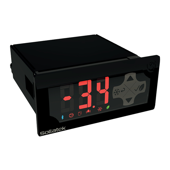
2. DESCRIPTION The JEA controller consists of three main groups of features: • The Front Display Panel with the user interface and controls. • The Rear Connector Panel for input, output, and data cables. • The Main Housing includes the mounting clips, mounting screws and bezel. 2.1 JEA FRONT PANEL - WITH DISPLAY ICONS BUTTONS... -
Page 7: Jea Front Panel - Without Display
Flashing (Four Seconds Defrost Mode ON/Four Seconds OFF) Flashing three times (Two Seconds Heater Control Mode (Winter Mode) ON/500mSec OFF) every 10 seconds See Section 11. Errors & Faults for LED patterns during equipment failure events. sollateksupport@sollatek.com I 7 JEA USER MANUAL... -
Page 8: Rear Connectors
2.3 REAR CONNECTORS 2.3.1 JEA WITH 4 RELAYS WARNING! MAINS CONNECTION Risk of electrocution or damage to equipment. Ensure Mains is isolated before installation or repair of the unit or any connected equipment. 10 Amp Relay Heater Sensor I/P Door Switch 90-250 VAC O/P NTC Temperature 10 kΩ... - Page 9 OP1 COMP 8(6)A 240VAC Compressor O/P2 8(6)A, 250Vac 8(6)A, 230Vac 1(1)A 240VAC / 2A 24VDC OP4 FAN O/P3 5A, 250Vac 2A, 230Vac OP5 LIGHT 2(2)A 240VAC / 4A 24VDC (LED) Light O/P4 5A, 250Vac 1A, 230Vac sollateksupport@sollatek.com I 9 JEA USER MANUAL...
-
Page 10: Installation
3. INSTALLATION 3.1 DIMENSIONS AND PANEL CUT-OUT 3.2 PANEL MOUNTING WARNING! Avoid installing the JEA in the following environments: • Strong vibrations or knocks • Exposure to continuous water spray • Aggressive and polluting atmospheres to avoid corrosion • Environments where explosive or mixes of flammable gases are present 1. -
Page 11: Wiring
1. Connect the Live-In (do not Loop to terminal 7), Neutral, Compressor, Heater, Fan and lights as described above. 2. Connect the DC Live to terminal 7 on the JEA. 3. Connect the fan and lights to the DC Negative. sollateksupport@sollatek.com I 11 JEA USER MANUAL... - Page 12 3.3.1.2 JEAx3 Models Standard Output Wiring (All outputs supplied with 90-300 VAC) 1. Connect the Live-In wire to terminal 2 on the JEA L in N in 2. Connect a loop from terminal 2 (Live-In) to terminal 6, Live-2-In on the JEA 3.
- Page 13 (SPPO3) Sollatek provides a connection cable for all devices which connect to the JEA to make connecting quick and easy. 1. Plug the 8-way connector of the connecting cable into the port on the rear of the JEA.
-
Page 14: Operation
4. OPERATION 4.1 OVERVIEW DAY NORMAL DAY - ECO CUT IN Temperature Probe CUT OUT Pull Down Compressor Evaporator Fan Lights OPEN Door CLOSE Time 14 I +44 (1753) 214 500 JEA USER MANUAL... - Page 15 DAY - SUPERFROST NIGHT - SUPERFROST NIGHT - NORMAL NIGHT - ECO sollateksupport@sollatek.com I 15 JEA USER MANUAL...
-
Page 16: Day And Night Mode
4.2 DAY AND NIGHT MODE In DAY mode, the temperature is lower to keep the products inside the cooler at the correct temperature for resale, and the lights are ON for Point of Sale (POS). In NIGHT mode the regulated temperature is higher than in DAY mode as the products do not need to be as cold, and the lights are OFF as no need for POS. -
Page 17: Winter Mode
Winter mode is entered automatically based on configurable parameters. Standard operation During Winter Mode Compressor: Evaporator fan: Cabinet Heater (if fitted): sollateksupport@sollatek.com I 17 JEA USER MANUAL... -
Page 18: Features
5. FEATURES 5.1 ENERGY SAVING The JEA tracks door openings. If no door openings are logged for a pre-set time (customisable) then the JEA will enter NIGHT mode. This is to maximise energy saving when the outlet is closed and no customer demand. 5.1.1 NORMAL, ECO AND SUPERFROST MODE Whichever mode: Normal, Eco or Superfrost, the JEA was running in during DAY mode, the JEA will remain in the same mode in NIGHT mode, i.e. -
Page 19: Protective Delays
This is to prevent short-term thermal effects such as those caused by the fan starting to operate causing disconnection. CUT IN Temperature Probe CUT OUT Less than Temperature Blind Time Compressor Time sollateksupport@sollatek.com I 19 JEA USER MANUAL... - Page 20 5.3.2 BAD VOLTAGE BLIND TIME The JEA provides high and low voltage protection by disconnecting the supply from the compressor and outputs if the voltage exceeds the set High Voltage Disconnect (HVD) or falls below the Low Voltage Disconnect (LVD) (both configurable). Once the voltage has returned with the reconnection voltage and delay timers have been satisfied, the JEA will automatically reconnect the outputs.
-
Page 21: Product Safety Features
5.5.1 BLUETOOTH JEA controllers are equipped with Bluetooth capability, enabling them to connect to the Sollatek Smart device Application. The Sollatek App has extensive cooler management capabilities. The JEA controller also features iBeacon and Eddystone Beacon capabilities allowing proximity marketing to send engaging and interactive content to consumers’... -
Page 22: Internal Rechargeable Battery
5.5.1.1 iOS And Android Smart Device Application The Sollatek Smart device application provides technicians with all the tools to view, configure and upload controller status and event data. • Real-time Data Analysis - View real-time telemetry data, operational status, and performance data. -
Page 23: Start-Up
Step3: The JEA will then display the live regulation temperature. On start-up the JEA will enter DAY-Normal mode of operation. 6.2 DISPLAY CHARACTERS For clarity on the display and to ensure readings and codes are easily identifiable, the below characters are used: Upper Case Characters: Lower Case Characters: Numerals: sollateksupport@sollatek.com I 23 JEA USER MANUAL... -
Page 24: Interface
7. INTERFACE 7.1 JEA FRONT DISPLAY 7.1.1 HOME DISPLAY FUNCTION • Manually toggle Eco Mode ON and OFF • Manually toggle Superfrost Mode ON and OFF • Manually toggle Lights ON and OFF • Manually toggle JEA ON and OFF 7.1.1.1 Home Display Flowchart Display = Short Button... - Page 25 If an incorrect button is pressed at any point, the display will revert to the home display. You will hear a long beep to indicate an incorrect password has been entered. • If at any point, there is a 20-second period of inactivity the display will revert to the home display. sollateksupport@sollatek.com I 25 JEA USER MANUAL...
- Page 26 7.1.2 MENU LIST In level 1 users can: • Configure Parameters • Reset parameters to factory-set • Reset the learning algorithm (self-learning models) 7.1.2.1 Menu List operational Flow Chart Display Temperature Enter Menu List = Short Button Press Enter Password Parameter Return Next Parameter...
- Page 27 Go to the menu list, and navigate to item “PrS” by Pressing the UP and DOWN buttons. Press the ENTER button to enter the value. The displayed value will be “no”. Change to “yes” with either the UP or DOWN button Press the ENTER button to confirm. sollateksupport@sollatek.com I 27 JEA USER MANUAL...
-
Page 28: Smart Device Application
7.2 SMART DEVICE APPLICATION (IF BLUETOOTH IS PRESENT) The Sollatek Smart device application provides a wireless connection to the JEA controller (via either internal BLE or external devices) from smartphones or tablets. This gives users access to controller and Bluetooth settings as well as live and historical telemetry data. -
Page 29: Desktop Interface Software
The JEA Interface software provides easy creation, checking and saving of parameters. 7.3.1 INSTALLATION AND LOGIN From the link provided by Sollatek, select all files, and click download. Click Open to open the folder location of the downloaded files. Run the setup file. Follow any security prompts to allow installation. A security message will pop up, click Install to continue the installation. - Page 30 2. Connect the JEA to a mains supply (Live & Neutral), then turn the power ON. Note: Parameters will not be uploaded unless the JEA is Powered ON 3. Open and log in to the JEA Interface using your credentials provided by Sollatek. To download Parameters from the JEA into the interface 4.
-
Page 31: Service Mode
There is also a safety timeout implemented to avoid accidentally leaving a cooler in Service Mode. If no command is received for more than 10 minutes while in Service Mode, the JEA resets and starts normal operation. sollateksupport@sollatek.com I 31 JEA USER MANUAL... -
Page 32: Parameters
9. PARAMETERS 9.1 PROBES SELECTION PARAMETER DESCRIPTION UNITS DEFAULT Temperature Control Probe (Air) Number N/A, 1 Defrost Control Probe Number N/A, 1 Condenser Control Probe Number N/A, 1 Ambient Control Probe Number N/A, 1 PIR Sensor Probe Number N/A, 1 Humidity Sensor Probe Number N/A, 1... -
Page 33: Temperature Regulation
ECO Mode Cut-Out – DAY The temperature at which the compressor will turn OFF when the system is running in Day-Eco mode. The compressor will remain ON until the temperature reaches the Cut-Out temperature. sollateksupport@sollatek.com I 33 JEA USER MANUAL... -
Page 34: Defrost
ECO Mode Cut-In – DAY The temperature at which the compressor will turn ON when the system is running in Day-Eco mode. If the temperature is below this value, the compressor will remain OFF SUPERFROST Mode Cut-Out – DAY The temperature at which the compressor will turn OFF when the system is running in Day-Superfrost mode. The compressor will remain ON until the temperature reaches the Cut-Out temperature. - Page 35 The minimum allowable time for a defrost cycle. The Defrost cycle will not end until this time has elapsed regardless of if Defrost Start Interval (df4) or Defrost Start Temperature (df6) have been met. sollateksupport@sollatek.com I 35 JEA USER MANUAL...
- Page 36 Minimum Duration Between 2 Consecutive Defrost Cycles The minimum allowable time between the finish of one defrost cycle and the start of the next defrost cycle. The next defrost cycle will not start until this time has elapsed regardless of if Defrost Start Interval (df4) or Defrost Start Temperature (df6) have been met.
-
Page 37: Voltage Protection Control
Maximum Compressor On Time Forced Defrost Hours N/A, 1 Maximum Compressor On Time Refrigeration Fault Hours N/A, 1 Compressor On Cycle Probe#1 Faulty - Day Minutes Compressor Off Cycle Probe#1 Faulty - Day Minutes sollateksupport@sollatek.com I 37 JEA USER MANUAL... - Page 38 Compressor On Cycle Probe#1 Faulty - Night Minutes Compressor Off Cycle Probe#1 Faulty - Night Minutes Compressor Protection Delay Initial Bypass Count Number N/A, 1 Intelligent Time Delay The minimum time the compressor must be OFF, before turning ON. If the compressor is OFF for longer than the set duration, then this delay will not be added before switching the compressor ON.
-
Page 39: Condenser Control
By Door (Dr): Lights will only turn ON when the door is open. When the door is closed the lights will turn OFF Light ON Delay (Night to Day Mode) The time delay between the controller switching from Night to Day mode, and the lights turning ON. sollateksupport@sollatek.com I 39 JEA USER MANUAL... -
Page 40: Door Operation
Light OFF Delay (Day to Night Mode) The time delay between the controller switching from Day to Night mode, and the lights turning OFF. Lights Switch Enable Select whether the state of lights will change with a button press No = Light button disabled. Lights will only turn ON/OFF with logic or if Refrigeration Failure Mode is entered Yes = Light button enabled. -
Page 41: Initial Pull Down
No = Fan is ON when the compressor is OFF. If set to No, Fd1, Fd2, Fn1, Fn2, FC1, FC2 & FC3 will be ignored Yes = Fan cycles when the compressor is OFF sollateksupport@sollatek.com I 41 JEA USER MANUAL... -
Page 42: Winter Mode
DAY Duty Cycle ON Time Compressor Cycles OFF The time the evaporator fan is ON when the compressor is OFF and the system is running in Day mode if Fan Cycle with Compressor (Fd0) is enabled. If 0 is set, the fan will remain on when the compressor if OFF. DAY Duty Cycle OFF Time Compressor cycles OFF The time the evaporator fan is OFF when the compressor is OFF and the system is running in Day mode if Fan Cycle with Compressor (Fd0) is enabled. -
Page 43: Ambient Condition Interaction
Enable Defrost in High Ambient Condition Select whether defrost occurs when the ambient temperature rises above nominal ambient conditions (An). Enable Ambient Temperature Interaction (AnA) must be enabled, and the ambient temperature probe is sollateksupport@sollatek.com I 43 JEA USER MANUAL... -
Page 44: Learning Algorithm
configured and present. No = Defrost is disabled when the ambient temperature is above An Yes = Defrost is enabled. Defrost will be triggered as normal depending on set defrost parameters. Nominal Ambient Condition The maximum temperature the ambient temperature can reach before adjustments to cut-in and cut-out values are made if Ambient Interaction Enabled (AnA) is set to Yes. -
Page 45: Interface
Communication Port Configuration Select the communication protocol for the JEA data connector JEA Interface (0) = Standard UART for communication with Sollatek external devices and JEA interface software. Modbus 9600 baud (1) = Modbus RTU communication with external devices Modbus 9600 baud (Inverted Logic) (2) = Modbus RTU communication with inverted logic states of Rx and Tx lines (e.g. -
Page 46: Firmware Update
Uploading the firmware onto the SPP03. 1. Open the SPP Visual Programmer Software, supplied by Sollatek. 2. Plug the SPP03 Programmer into the computer’s USB port, if plugging in for the first time please wait for all the drivers to be installed before proceeding. -
Page 47: Over The Air Update
SPP03 Visual Programmer User Instructions for more details and troubleshooting. 10.2 OVER THE AIR UPDATE (if Bluetooth is present) If the JEA has built-in or is connected to an external Bluetooth device, the JEA firmware can be updated using the Sollatek smart device application. -
Page 48: Bluetooth Firmware Update
10.3 BLUETOOTH FIRMWARE UPDATE THROUGH THE APP (if Bluetooth is present) 1. Open the Sollatek smart device app on your phone/tablet. Login using your credentials. 2. Find the required JEA from the list of BLE devices. Connect the device to the app by clicking the icon in the device header. -
Page 49: Errors And Faults
Yellow Compressor Icon: • Red Alarm Icon: Flashing three times (50 ms ON/250 ms OFF) every 4 seconds If the probe is selected as the regulation probe the display will toggle between -50 and PF3. sollateksupport@sollatek.com I 49 JEA USER MANUAL... -
Page 50: Ambient Sensor Failure
11.4 AMBIENT SENSOR FAILURE • Set points (cut-in and cut-out values) are as programmed and are not adjusted due to ambient conditions. • All other operations as normal With Display • Master Alarm Indicator: • Main Display: Toggles between the regulation probe temperature and PF4 assuming default probe selection. -
Page 51: Condenser Over Temperature
Toggles between the regulation probe temperature and AOt Without Display • Green Power Icon: • Yellow Compressor Icon: • Red Alarm Icon: Flashing (2 s ON / 500 ms OFF) • Defrost is disabled sollateksupport@sollatek.com I 51 JEA USER MANUAL... -
Page 52: Refrigeration Failure
11.11 REFRIGERATION FAILURE Refrigeration Failure Mode will be initiated if any of the following events take place: • The compressor has been running continuously for longer than Cd6 • 3 consecutive defrost cycles due to Cd5 • Condenser temperature (when condenser probe is enabled and not faulty) exceeds OH over 3 consecutive events •... -
Page 53: Specification
Customisable colour to match cooler aesthetics (Not supplied with JEA) BLUETOOTH AND BATTERY (OPTIONAL) Version 4.1 BLE Bluetooth Connectivity iBeacon, Eddystone & connection to the Sollatek smart device application Memory On-board storage of approx. 13,000 events Type Rechargeable Lithium coin battery Nominal Voltage Battery... - Page 54 VOLTAGE PROTECTION Powered By External Mains Power Operating Voltage 90 - 300 VAC Voltage Protection High and Low voltage disconnect Immediate Disconnect Voltage 60 / 300 VAC Low Voltage Blind Time 0 - 255 sec High Voltage Blind Time 0 - 255 sec Working Frequency Auto-sense 45/65 Hz Surge Protection...
-
Page 55: Accessory List
CABLE 2X4 WAY TO µUSB 2M 95342WB0 GMC4-2BBW 2G 95344WB0 GMC4-4BBW 4G JEA-GMC4 Cable EXTERNAL DISPLAY PRODUCT CODE PRODUCT DESCRIPTION 92363DR0 FFD-R DIGITAL DISPLAY MODULE RED 8M293490 JEA TO FFD DISPLAY CABLE 2M DWG 3816.01 sollateksupport@sollatek.com I 55 JEA USER MANUAL... -
Page 56: Version History
92393R00 FDM3R 14MM RED 3 DIGIT DISPLAY 92393B00 FDM3B 14MM BLUE 3 DIGIT DISPLAY 92393BNS FDM3B 14MM BLUE 3 DIGIT DISPLAY N/S 92393G00 FDM3G 14MM GREEN 3 DIGIT DISPLAY 8M293490 JEA TO FFD DISPLAY CABLE 2M DWG 3816.01 PROGRAMMING Product Code Product Description 90500500 SPP03 FFA-GMC0-GMC2... - Page 57 This page intentionally left blank sollateksupport@sollatek.com I 57 JEA USER MANUAL...
- Page 58 The information in this document has been carefully checked and is believed to be accurate. Nevertheless Sollatek assumes no Sollatek (UK) Ltd. Sollatek House, Waterside Drive, Langley, Slough SL3 6EZ UK responsibility for any errors or omissions. JEA User Manual Aug 2023 v1.11...
Need help?
Do you have a question about the JEA Series and is the answer not in the manual?
Questions and answers