
Summary of Contents for FIEDLER H531
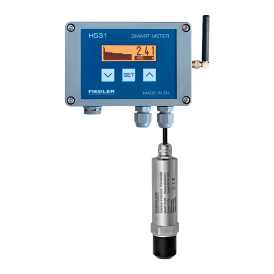
- Page 1 H531 Level gauge user manual version 1.03 Level measurement in wells, boreholes, tanks and sumps...
- Page 2 H531 level gauge assembly User manual FIEDLER electronics for ecology...
-
Page 3: Table Of Contents
H531 level gauge assembly User manual CONTE 1. SAFETY INSTRUCTIONS 2. USING THE LEVEL GAUGE 3. QUICK INSTALLATION OF THE LEVEL GAUGE 3.1.1. I NSTALLING THE LEVEL SENSOR 3.1.2. I NSTALLATION OF THE DISPLAY UNIT 4. BASIC DESCRIPTION 4.1. L EVEL SENSORS 4.1.1. -
Page 4: Safety Instructions
H531 level gauge assembly User manual Safety instructions • The installation of a level gauge with external power supply must be carried out by a person with the necessary qualifications for the installation of elec- trical equipment. The installer must carry out the installation in accordance with all instructions, regulations and standards relating to safety and electro- magnetic compatibility. -
Page 5: Using The Level Gauge
GSM/GPRS or NB-IoT network (H531- G or H531-N level gauges). The user can then monitor the level remotely via a web browser. A special server service can also ensure that a warning SMS is sent when a preset level is reached. -
Page 6: Quick Installation Of The Level Gauge
H531 parameters, the display will also show a level height in the i m m e r s i o n d e p t h range of 0 to 10 m, depending on the depth of immersion of the sensor below the measured water level. -
Page 7: Installation Of The Display Unit
The approach to the Delta parameter is given in chap. 3-4-3 Delta on p. 31. 3.1.2. Installing the display unit The H531 display unit is usually placed close to the measured level. The maxi- mum possible distance between the submerged transducer and the display unit is determined by the length of the connection cable between the transducer and the unit. -
Page 8: Basic Description
Each level sensor includes a cable that suspends the sensor and connects it to the H531 display unit. Since the cable is an integral part of the sensor, the length of the cable along with the measurement range of the sensor must be specified when ordering the sensor. -
Page 9: Absolute Level Sensor
The TSH27 can be supplied with a different cable length for an additional charge. The sensors have a measurement accuracy of 2.5% of the range and an output signal of 0..5 V DC. The H531 unit is factory set to connect this type of absolute encoder. TSH27 absolute sensor (without sensor cap) TSH27-10/25 sensor with measuring range 0..10 mH... -
Page 10: Pressure Compensated Level Sensors
(h) above the sensor. There are many pressure compensated sensors on the market and most of them can be easily connected to the H531. The following overview lists the 2 basic types of recommended pressure compensated sensors suitable for connection to the H531 display unit. - Page 11 H531 level gauge assembly User manual LMK809-X/Y LEVEL SENSORS (4-20 MA OUTPUT) Pressure compensated level sensor with plastic body and ceramic diaphragm. These sensors are suitable for level measurement even in heavily polluted wastewater. The sensor has a current output of 4-20 mA and typical measurement accuracy is better than 1% of the measurement range.
-
Page 12: H531 Imaging Unit
Cable gland for connection of the immersion level sensor. M e c h a n i c a l The H531 level gauge display unit is housed in a 120 x 80 x 55 mm plastic box a r r a n g e m e n t with IP66 protection. -
Page 13: Power Supply For The Level Gauge
[7]. When the binary transistor output of the H531 unit is switched on, an icon indi- cating this condition appears in the upper left window of the graph. -
Page 14: Description Of Terminals And Configuration Jumpers Of The H531 Unit
User manual 4.2.3. Description of terminals and configuration jumpers of the H531 The circuit board inside the H531 unit contains connection terminals and jump- ers for selecting the level sensor to be used. Replaceable power supply battery type ER34615 (ER34615M for H531-G) -
Page 15: Installation
H531 level gauge assembly User manual Installation 5.1. Mechanical installation 5.1.1. Installation of the TSH27 absolute level sensor I n s t a l l a t i o n b y The submersible level sensor can be simply lowered by cable i m m e r s i o n into the measured object (well, sump, etc.) to such a position... -
Page 16: Installation Of A Pressure Compensated Level Sensor
Hanger-U designed to lower the pressure compensated transducer by the cable to the de- sired depth of the tank/sump/well to be measured. 5.1.3. Extension of the connection cable If necessary, the connection cable between the sensor and the H531 display unit can be extended. N o t e... -
Page 17: Installation Of The H531 Display Unit
H 5 3 1 Since the H531 unit includes a display and knobs for controlling the unit, it is advisable to install the unit in an easily accessible location and preferably at eye level. -
Page 18: Electrical Wiring
User manual 5.2. Electrical wiring 5.2.1. Connecting the level sensor to the H531 unit The detachable series terminal block with terminals 1 to 6 is designed for con- necting a level sensor. The colour coding of the individual cores and their con- nection can be seen in the following figures. -
Page 19: Connecting An External Power Supply To The H531
9 [EXT] and the negative terminal to ter- minal 8 [GND]. An external power supply is only required when operating the H531 unit with the backlit display permanently on or in the case of frequent data transmissions to the server for level gauges equipped with a communication module (H531-G or H531-N). -
Page 20: Connecting A Relay Or Other Power Element To H531
24 V DC and 12 V DC respectively. However, the external supply voltage of the H531 level gauge can range from 5 V to 28 V DC. INSTALLATION NOTE H531 FOR PUMP CONTROL OR EL. VALVE... -
Page 21: Parameters
6.1.1. Parameter display The display and editing of individual H531 parameters is done in the Main Menu. Entering the menu, changing individual parameters and then exiting the menu is done using the three control buttons UP, DOWN and SET (see picture on p. -
Page 22: Structure Of The H531 Menu
H531 level gauge assembly User manual 6.1.2. MENU structure H531 The parameters of the level gauge are thematically divided into six basic groups, which form the structure of the main menu of the level gauge. The seventh group 7. Info does not contain adjustable parameters, but is used to display selected quantities and identification and production data of the level gauge. -
Page 23: Parameter Editing Procedure
H531 level gauge assembly User manual 6.2. Procedure for editing parameters The selected parameter can be changed by repeatedly pressing the SET knob, which switches the display mode from displaying the measured level to param- eter editing mode using the nested MENU menu. - Page 24 H531 level gauge assembly User manual Change the "Measurement interval" parameter from 60 min to 1 min E x a m pl e 4 . 1. Default mode Main MENU: ▪ Access to the Main MENU after repeated pressing of the SET knob ▪...
-
Page 25: Basic Factory Settings Of The H531 Level Gauge
6.3. Basic factory settings of the H531 level gauge The H531 level gauge is set by the manufacturer to measure and display the level within the measuring range given by the level sensor used. Thus, even without further parameter setting, the level gauge can be used for a basic dis- play of the water level above the submerged transducer. -
Page 26: Description Of Individual H531 Parameters
[s] after touching one of the instrument buttons. Permanently on In this operating mode, the H531 level gauge including the display is perma- nently switched on and the level gauge continuously measures and displays the measured level using the connected sensor regardless of the parameter setting 3-2-3 Measurement interval. - Page 27 Immediate blocking of access to the unit MENU is done by selecting the option 3-8 Log out (the last item in the main MENU of the H531 unit). The value of the Password = 000 (zero) parameter disables the request to enter the Password.
- Page 28 User manual 3-3 Display view A group of parameters for setting the operating mode of the H531 backlit LCD display, including setting the display range of the left vertical axis of the graph and the time period for graphical display of the measured level.
- Page 29 H531 level gauge assembly User manual Minutes per pixel 3-3-3 This parameter sets the time period in minutes that will be displayed as a single bar (pixel) on the level graph. The graph consists of a total of 72 columns, i.e. depending on the value of this parameter, it shows a time period ranging from 3 days to approximately 5 weeks.
- Page 30 N o t e Operation of the level gauge with permanently switched on and illuminated dis- play can only be enabled when the H531 is powered from an external mains voltage source (see chap. 5.2.2 Connecting an external power supply to the H531 on p.
- Page 31 The used measuring range of the connected absolute level sensor is already set into the H531 unit at the time of manufacture of the level gauge, and the user's choice of measuring range is therefore overridden for these types of sensors.
- Page 32 However, a slight difference in the atmospheric pressure measurement between the TSH27 sensor and the H531 unit may occur over time and is usually due to the aging of the TSH27 sensor. Other reasons for calibration include, for example, replacement of the TSH27 sensor with a sensor with a different measuring range or replace- ment of a damaged TSH27 sensor.
- Page 33 3-5-1 Menu for setting the automatic control of the OK transistor binary output of the H531 level gauge unit according to the set limit limits and the current measured level. In addition, the options in this menu can be used to force the OK binary output on or off regardless of the set switching limits and the current measured level (so-called manual control).
- Page 34 H531 level gauge assembly User manual The following two figures graphically show the limit value settings 3-5-2 Switch- ing limit [m] a 3-5-3 Extension limit [m] for automatic water supply and pumping in 1-2 Auto mode. The red curve in the right part of the pictures indicates the level change in time, the grey shading "On"...
- Page 35 H531-G (H531-N) to the cloud (see chapter 7. Remote access on p. 40). The basic version of the H531 does not include any communication module and therefore the data transfer parameters cannot be set by this unit.
- Page 36 Signal test 3-6-3 Start the procedure to measure the GSM field strength at the H531-G installa- tion site. For reliable transmission of the measured data to the database on the Internet server, a GSM field strength of at least 15% from 0 to 100% is required.
- Page 37 Menu option for emergency and user-provoked data transfer to the server out- side the set transfer interval. This option can be useful, for example, when in- stalling the H531-G level gauge and then checking the currently measured data displayed in the cloud application on the server.
- Page 38 H531 level gauge assembly User manual 3-7 Info This last menu in the H531 menu is used to display selected quantities and iden- tification and production data of the level gauge. The displayed values cannot be changed and are mainly for diagnostic purposes.
- Page 39 H531 level gauge assembly User manual Number of OK transmissions Number of data sessions made to the server via the communication module. Number of ERR transmissions Number of failed data sessions to the server due to communication er- rors. Usually, the main cause of incomplete data sessions is a weak radio network field at the device installation site or low battery voltage.
-
Page 40: Remote Access
A v a i l a b l e t y p e s o f The following overview table lists the available or upcoming types of H531 level H 5 3 1 l e v e l g a u g e s... -
Page 41: Architecture Of The Data Acquisition System
7.1. System architecture data collection 7.1.1. Active stations system The H531-G and H531-N are characterized by long battery life and very low op- erating costs with regular data transfer to the server. This has been achieved by a system of active stations (level gauges) and a passive server. The server is al- ways on and waiting for data from the individual stations, which themselves de- termine when the data will be transmitted to the server. -
Page 42: Level Gauge H531-G
0 to 100% at the location of the H531-G. At lower signal strengths, some GPRS data sessions may not take place at all or only on other days with better GSM signal propagation conditions. -
Page 43: Parameters Of The H531-Glevel Gauge
12 mm diameter hole with a threaded nut. DISPLAY OF GSM FIELD STRENGTH WHEN INSTALLING A LEVEL GAUGE The current intensity of the GSM field at the installation site of the H531 level gauge can be found by running the "Signal test" procedure in the "Data transfer"... -
Page 44: Technical Parameters
H531 level gauge assembly User manual Technical parameters D i s p l a y u n i t H 5 3 1 Analog measurement input voltage 0-5 V or current 4-20 mA / 0-20 mA (se- lectable via jumpers and parameters) - Page 45 H531 level gauge assembly User manual Measurement accuracy ± 1 % of measuring range Output signal 2-Wire: 4-20 mA Supply voltage 8-28 V DC /max 25 mA Connection cable shielded PUR cable -0° C ... +50 C ° Operating temperature range Sensor material stainless steel housing.
- Page 46 Warranty Card H531 level gauge assembly User manual Type: H531___ v. no.: ___________ Date of sale: ______________ Sensor: _______ v. no.: ___________ .............. Manufacturer / Supplier The product was tested and set up correctly before being shipped from the company. Nevertheless, it may happen that during operation, defects may appear on the device that are undetectable when the product is tested by the manufacturer.
- Page 47 H531 level gauge assembly User manual FIEDLER electronics for ecology...
- Page 48 H531 level gauge assembly User manual CRJF231127.103c H531, H531-G Manufacturer: FIEDLER AMS s.r.o. Lipová 1789/9 370 05 České Budějovice FIEDLER electronics for ecology www.fiedler.company Tel: +420 386 358 274...
Need help?
Do you have a question about the H531 and is the answer not in the manual?
Questions and answers