
Subscribe to Our Youtube Channel
Summary of Contents for Crate Pro Audio CSM12
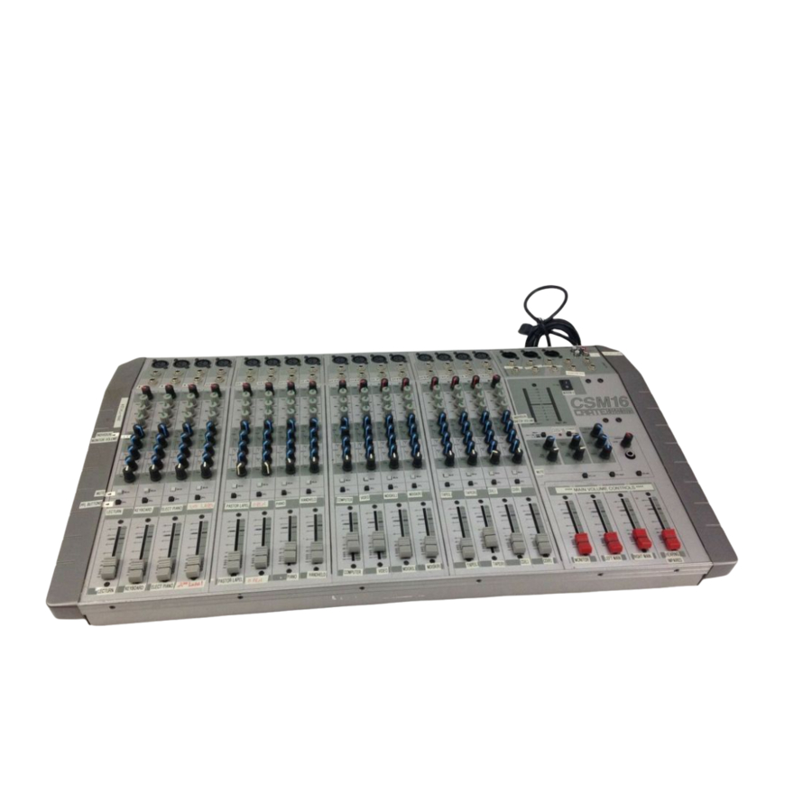
- Page 1 User’s Guide for the C R AT E P R O A U D I O CSM8/12/16/24 Console Mixer In order to achieve maximum performance from your new Crate Pro Audio Mixer we recommend that you read this user’s guide prior to its use.
-
Page 2: Table Of Contents
Congratulations. You have selected one of the finest pieces of audio reproduction equipment available for use on stage, in the home studio, or for “institutional” use: a Crate Pro Audio Stereo Console Mixer. In order to derive the most benefit from the mixer, and to fully understand and appreciate its flexibility and versatility, please familiarize yourself with the mixer by reading through this User’s Guide prior to its use. -
Page 3: Introduction
CSM8/12/16/24 Console Mixer Introduction: In the world of professional sound reinforcement and audio reproduction there is no room for compromise. It is absolutely vital that the emotions of a performance are projected to your audience, not just sounds. Your new Crate Pro Audio CSM8/12/16/24 Console Mixer is a powerful tool which allows you to successfully bridge the gap between performers and audience without losing any of the “life”... -
Page 4: The Input Channels
The Input Channels: CSM8/12/16/24 Console Mixer 1. LOW Z INPUT: The signal output from a low impedance microphone or a low impedance line level signal (such as a line out signal from an instrument ampli- fier) may be connected here by means of a shielded cable terminated with a male XLR plug. -
Page 5: The Master Section
The Master Section: CSM8/12/16/24 Console Mixer 15. LEFT, RIGHT AND MIX BALANCED OUTPUTS: Use these jacks to send the mixer’s output signal(s) to the house power amplifier(s) (see pages 9–13). For the XLR jacks, pin 2 = “+,” pin 3 = “–,” and pin 1 = shield. For the 1/4”... - Page 6 The Master Section (continued): CSM8/12/16/24 Console Mixer 23: PHANTOM POWER: This switch, when depressed, applies 48 volts DC to pins 2 and 3 of the each channel’s low Z input jacks (#1, page 4) to accommodate microphones which require a source of phantom power for proper operation.
-
Page 7: Equalization Diagrams
CSM8/12/16/24 Console Mixer Equalization Diagrams: Each input channel of the CSM8/12/16/24 has three bands of equalization which let you alter the tonal characteristics of the input signal. The EQs may be used to add “color” or to compensate for inadequacies of the original signal. They also may be used to cut frequencies to help eliminate unnatural sounds or to de-emphasize over-pronounced tones, and to help prevent acoustic feedback. -
Page 8: Connecting External Effects
Connecting External Signal Processors: There are several ways to use external signal processors with the CSM8/12/16/24. Each of the mixer’s input channels has its own Insert jack, allowing a processor to be used on that particular channel. Figures 1 and 2 below show two ways of con- necting a signal processor to the channel Insert jacks. -
Page 9: Applications
CSM8/12/16/24 Console Mixer Applications: Basic Mono Operation: This setup shows one way of using the mixer and one stereo power amplifier to run both the house speakers and the stage monitors. Two mono power amplifiers may be used in place of the one stereo amplifier. Connect the components as follows: (A) Connect a balanced or unbalanced signal cable between the mixer’s Mix Balanced Output and the power amplifier’s Channel 1 Input. -
Page 10: Applications
Applications: Basic Stereo Operation: This setup shows one way of using the mixer and two stereo power amplifiers to run the system. By using both Aux 1 and 2 for monitor sends, a separate monitor mix can be had for each of two sets of monitor speakers. Connect the components as follows: (A) Connect a balanced or unbalanced signal cable between the mixer’s Left Balanced Output and the house power ampli- fier’s Channel 1 Input. -
Page 11: Applications
CSM8/12/16/24 Console Mixer Applications: DJ Setup: This setup shows one way of using the mixer and one stereo power amplifier to run the house speakers for a mobile DJ setup. Two mono power amplifiers may be used in place of the one stereo amplifier. Connect the components as follows: (A) Connect a balanced or unbalanced signal cable between the mixer’s Left Balanced Output and the house power ampli- fier’s Channel 1 Input. -
Page 12: Applications
Applications: House of Worship Installation: This setup shows one way of using the mixer and one stereo power amplifier to run both the house speakers and the stage monitors. Two mono power amplifiers may be used in place of the one stereo amplifier. Connect the components as follows: (A) Connect a balanced or unbalanced signal cable between the mixer’s Left Balanced Output and the house power ampli- fier’s Channel 1 Input. -
Page 13: Applications
CSM8/12/16/24 Console Mixer Applications: Separating Vocals and Instruments: This setup shows one way of using the mixer, one stereo and one mono power amplifier to run the system. Two sets of house speakers are required in this application: one for the vocals, the other for the instruments. Connect the components as follows: (A) Connect a balanced or unbalanced signal cable between the mixer’s Left Balanced Output and the house power ampli- fier’s Channel 1 Input. -
Page 14: System Block Diagram
System Block Diagram: PHANTOM +48V POWER LOW Z PEAK/ SIGNAL HIGH Z TYPICAL INPUT CHANNEL GAIN INSERT CHANNEL FADER HIGH MID LOW AUX 3 RETURN AUX 4 RETURN CSM8/12/16/24 Console Mixer AUX 1 AUX 2 AUX 3 AUX 4 MUTE AUX 3 RETURN AUX 3... -
Page 15: Gain Level Diagram
CSM8/12/16/24 Console Mixer Gain Level Diagram: GAIN LINE MAX LINE +26dB MAX. INPUT - SET GAIN AS NECESSARY MAX MIC +13dB ALL LEVELS @NOMINAL, LINE -35dB FULL GAIN MIC -49dB LINE -55dB MIC -72dB -120 NOISE FLOOR -120dB FADER INSERT +21dB +3dB -7dB... - Page 16 CSM8/12/16/24 Console Mixer Technical Specifications SYSTEM INPUTS CSM8 8 mono mic/line input channels CSM12 12 mono mic/line input channels CSM16 16 mono mic/line input channels CSM24 24 mono mic/line input channels All models 2 stereo effects returns 1 stereo tape input...
Need help?
Do you have a question about the Pro Audio CSM12 and is the answer not in the manual?
Questions and answers
Wireless mic not playing on both speakers
The Crate CSM12 wireless mic may not be playing on both speakers if it is connected to a mono input channel and the panning or output routing is not set correctly. Also, if only one side of the mixer’s output (Left or Right) is connected to the amplifier or speaker, sound will only come from one speaker. Check the mic channel's pan setting, ensure both Left and Right outputs are connected to the amplifier, and verify the amplifier is outputting to both speakers.
This answer is automatically generated