
Related Manuals for Airflow Adroit DV50


Summary of Contents for Airflow Adroit DV50
- Page 1 DV50 DV80 DV50 DV80 Instruction Manual © Airflow • We reserve the right to make changes without prior notice...
- Page 2 DV50 DV80...
-
Page 3: Table Of Contents
7. EXPLODED VIEW AND PARTS LIST 8. USER LEVEL DIAGRAMS 9. CERTIFICATE OF CONFORMITY 10. COMMISSIONING THE SYSTEM 11. WARRANTY NOTE: You can sign into your Adroit account at: www.airflowadroitcontrol.com © Airflow • We reserve the right to make changes without prior notice... -
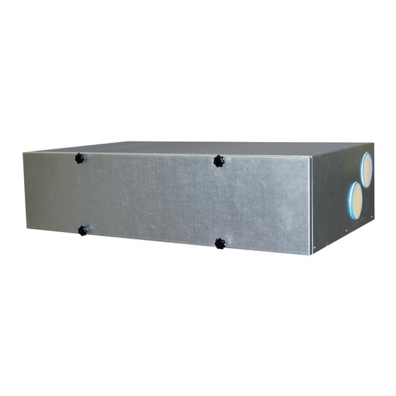
Page 4: Introduction
EXTRACT AIR FAN SAFETY SWITCH OPTIONAL POST-HEATER 900W ADROIT DIGITAL CONTROLLER HEAT RECOVERY CELL ADROIT CO TRANSMITTER OUTDOOR AIR FILTER F7 ADROIT HUMIDITY TRANSMITTER OUTDOOR AIR FILTER G4 EXTRACT AIR FILTER G4 NOTE For more detailed instructions, go to www.airflow.com... -
Page 5: System Description
9. Click on the link given in this e-mail to verify your e-mail address. The lastest browser versions on 10. You are now connected to the Adroit Cloud. mobile devices. © Airflow • We reserve the right to make changes without prior notice... - Page 6 DV50 DV80 INTRODUCTION GENERAL SAFETY INSTRUCTIONS For safe and proper handling, it is necessary to know the basic safety regulations and the intended usage of the ventilation system. Read this manual before operating the ventilation unit. Keep this manual for later use. In case of loss, you can download the manual from our website.
-
Page 7: Adroit Digital Controller
These icons indicate the hierarchy level of the settings. This icon indicates when the feature is turned off at your user level. The parental controls lock code is 1001. © Airflow • We reserve the right to make changes without prior notice... - Page 8 DV50 DV80 INTRODUCTION INTRODUCTION WARNING Ventilation has to be constant for the indoor air to stay healthy for the dwellers and the structures of the dwelling. Even for longer The unit is not intended for use holidays, it is not advisable to stop the ventilation, because the by children under 8 or by persons indoor air will become stuffy and, during the heating season, the with reduced sensory, physical or...
-
Page 9: Deployment Wizard
Select Right arrow. Use the Plus and Minus buttons to set the minutes. The time is now set. Proceed to the next phase by selecting Right arrow. © Airflow • We reserve the right to make changes without prior notice... - Page 10 DV50 DV80 BASIC SETTINGS SET THE 24 OR 12 HOUR CLOCK By default, the system uses a 24 hour clock. If you want to use the 24 hour clock, proceed to the next step by pressing the Arrow right button. If you want to use the 12 hour clock, proceed as follows: Press the Minus button.
-
Page 11: Expert Settings
You can browse the Password and accessrights settings with the Right arrow button. NOTE The access code of the parental controls cannot be changed. The access code is always 1001. © Airflow • We reserve the right to make changes without prior notice... - Page 12 DV50 DV80 EXPERT SETTINGS FAN SETTINGS To set the output ratio between the supply and extract air fans: WARNING The ventilation specialist has made IMPORTANT the supply and exhaust air settings Adjust the air flows according to the values specified in the when deploying the ventilation ventilation plan.
- Page 13 Boost profile in the same way as for the At home and Away profiles. The Boost profile also has a timer setting. © Airflow • We reserve the right to make changes without prior notice...
- Page 14 DV50 DV80 EXPERT SETTINGS AWAY PROFILE When you want to make the Away profile settings, proceed as follows: 1. The deployment wizard Away profile screen is opened. NOTE Once you have set the fan speed for the At home profile, the fan speed for the Away profile will default to -30% of the At home profile fan speed.
- Page 15 16. The timer duration setting screen appears. 17. Set the profile timer duration in minutes by using the Plus and Minus buttons. 18. Press the OK button. © Airflow • We reserve the right to make changes without prior notice...
- Page 16 DV50 DV80 EXPERT SETTINGS FIREPLACE PROFILE When you want to make the Fireplace function settings, proceed as follows: 1. The deployment wizard Fireplace function profile screen is opened. 2. Set the profile timer duration in minutes by using the Plus and Minus buttons.
-
Page 17: Using The Unit
• Red — The carbon dioxide level is significantly higher than normal. The fan speed will be automatically increased if automatic adjustment is allowed. © Airflow • We reserve the right to make changes without prior notice... - Page 18 DV50 DV80 VENTILATION PROFILES CHANGING THE PROFILE If you want to change the ventilation profile, proceed as follows: Press the Change profile button until the desired ventilation profile icon appears on the display. Wait until the main display of the ventilation profile appears. The ventilation profile has been changed.
- Page 19 TIMER FUNCTIONS OF THE BOOST AND FIREPLACE PROFILES In the Boost and Fireplace profiles, also the timer function can be modified as described in the section Deployment wizard > Profile settings. © Airflow • We reserve the right to make changes without prior notice...
-
Page 20: Temperatures And Sensors
DV50 DV80 TEMPERATURES AND SENSORS VIEWING TEMPERATURE DATA Select Settings > Temperatures and sensors. Select OK. The summary display of temperatures and sensors shows the following information: • Indoor — Indicates the temperature of the air flowing into the unit to be removed from the premises. •... - Page 21 Carbon dioxide level statistics for the past week. You can view the graph for a week or for a single day. You can view the graph for a week or for a single day. © Airflow • We reserve the right to make changes without prior notice...
- Page 22 DV50 DV80 SETTINGS FILTER SETTINGS Select Settings > Filter. Select OK. The summary display of the filter status shows the following information: • Filters replaced — Indicates the date when the filter was last replaced. • Next reminder — Indicates the date when a reminder to replace the filters will next be shown.
- Page 23 Press the OK button. SELECTING THE USER INTERFACE LANGUAGE Select Settings > Language. Press the OK button. Select the language you want, for example: English. Press the OK button. © Airflow • We reserve the right to make changes without prior notice...
- Page 24 DV50 DV80 SETTINGS TIME AND DATE SETTING THE TIME AND DATE The available time settings are: • Time • 24 or 12-hour clock • Automatic daylight saving time • Date NOTE The unit time will withstand a power cut of a few hours. SETTING THE TIME Select Settings >...
- Page 25 Select Settings > Week clock off. Select OK. Select Settings. Select Turn on - week clock. Select Select. The control panel confirms that the week clock is turned on. © Airflow • We reserve the right to make changes without prior notice...
- Page 26 DV50 DV80 SETTINGS WEEK CLOCK SETTING AND EDITING THE WEEKLY PROGRAM Select Settings > Week clock on. Select OK. Use the Right arrow button to select the desired day. Use the Down arrow button to select the desired time. Use the Select button to browse and select the ventilation profile that will be turned on at the chosen time.
- Page 27 To re-start the ventilation unit, press any key. © Airflow • We reserve the right to make changes without prior notice...
-
Page 28: Maintenance
• The coarse filter (C) filters the extract air and keeps the heat recovery cell clean. Using original Airflow filters ensures To replace the filters: that the ventilation unit remains in top Disconnect the ventilation unit from the mains electricity condition, giving the best results. -
Page 29: Heat Recovery Cell
13. The heat recovery cell has now been checked and cleaned. NOTE If the unit has an enthalpy cell, it must not be washed. Only aluminium or plastic cells can be washed. © Airflow • We reserve the right to make changes without prior notice... -
Page 30: Fans
DV50 DV80 MAINTENANCE INSTRUCTIONS FANS Check the cleanliness of the fans when servicing the filters and the heat recovery cell. Clean the fans as required. You can clean the fan blades with compressed air or by brushing them gently. Do not remove or move the fan blade balancing weights. -
Page 31: Condensing Water
The air lock ensures the removal of WARNING condensing water and muffles any noise. Water must be kept out of the electrical system at all times. © Airflow • We reserve the right to make changes without prior notice... -
Page 32: Troubleshooting
DV50 DV80 MAINTENANCE INSTRUCTIONS TROUBLESHOOTING NOTE The table below contains troubleshooting and fault repair instructions. Error messages are displayed on the control panel and in the ADROIT Home and ADROIT Cloud services. FAULT CAUSE MEASURES Message on the user interface: The extract air fan has stopped. -
Page 33: Technical Specifications
Supply air G4 +F7 Extract air Optional post-heater 900W, 3.9 A Heat recovery bypass Motorized summer/winter damper Heat recovery Cross-counter flow cell, h>80 % Weight 58.5 kg © Airflow • We reserve the right to make changes without prior notice... - Page 34 DV50 DV80 DV50 ADROIT TECHNICAL SPECIFICATIONS MEASUREMENT POINTS FAN INPUT POWER Measurement points after the connection outlet. The fan curves indicate the total 100% pressure accounted for by duct losses. Supply air Extract air VIEW FROM ABOVE Volume flow rate AIR VOLUMES DV ADROIT, SUPPLY AIR (F7+G4), EXTRACT AIR (G4) extract air PK and TK are examples of...
- Page 35 116.28/132.48 84.24/100.08 54.36/70.2 , dB (A) 53.5 51.2 49.5 45.9 42.0 37.4 34.4 *28.9 *24.7 * The background noise requirement of standard ISO 3741:2010 is not met © Airflow • We reserve the right to make changes without prior notice...
-
Page 36: Internal Electrical Connection
DV50 DV80 INTERNAL ELECTRICAL CONNECTION CABLE COLOURS Black Blue 230 V 50 Hz Brown MB_A MB_A White MB_B MB_B +24V +24V RS_A RS_A RS_B RS_B Grey TESTER Yellow Yellow- +24V YEGN +24V RS_A green RS_A RS_B RS_B +11V1 +24V AN/I D/I1 RM/I +24V... -
Page 37: External Electrical Connection
Analog input 0-10 VDC RS_A Local hardware Modbus A signal RM/I 24 V relay input RS_B Local hardware Modbus B signal RM/O 24 V relay output External temperature sensor connector © Airflow • We reserve the right to make changes without prior notice... -
Page 38: Installation
DV50 DV80 INSTALLATION INSTALLATION SITE DV 50 / 80 must be installed in a location where the temperature remains above +10 °C. When the unit is installed without a protective enclosure, the location must be chosen so that its noise does not cause any disturbance. Such locations include storage premises, technical spaces, and false ceilings. -
Page 39: Dimensions And Duct Outlets
Water seal Power plug cable and SC Space required Water outlet speed switch cable for installation (option) UNIT DIMENSIONS Dimension DV50 DV80 Adroit Adroit SERVICE SPACE 1060 1026 © Airflow • We reserve the right to make changes without prior notice... -
Page 40: Condensing Water Outlet
DV50 DV80 INSTALLATION CONDENSING WATER The delivery includes a water seal and a water outlet for connecting the pipe that leads the water condensed from the extract air to the floor drain (not directly into the sewer). The pipe must not rise after the water seal. See the accessory bag for further instructions on the installation of the water seal and the water outlet. -
Page 41: Exploded View And Parts List
Adroit CO Transmitter (optional) 90000613 Post-heater 900W (optional) DV50&80 L model 60000132 Additional heater 900W (optional) DV80 R model 60000131 Additional heater 900W (optional) DV80 L model 60000132 © Airflow • We reserve the right to make changes without prior notice... -
Page 42: User Level Diagrams
DV50 DV80 USER LEVEL DIAGRAM EXTENSIVE Away Away information Edit Error log At home At home information Edit Cell defrost Turn unit on Boost information Boost Edit Self test display Setup Fireplace profile Fireplace info Edit Diagnostics display Fan test Service menu Heater test Language... -
Page 43: Certificate Of Conformity
May 2016 Managing Director Airflow Developments Limited Aidelle House, Lancaster Road, Cressex Business Park High Wycombe, Buckinghamshire. HP12 3QP, U.K. T: +44 (0)1494 425252 E: info@airflow.com W: airflow.com © Airflow • We reserve the right to make changes without prior notice... -
Page 44: Commissioning The System
• Has been installed in accordance with latest Building Regulations and IEEE wiring regulations by a recognised competent installer. Airflow Developments Ltd shall not be liable for any loss, injury or other consequential damage, in the event of a failure of the...
Need help?
Do you have a question about the Adroit DV50 and is the answer not in the manual?
Questions and answers