Advertisement
Table of Contents
- 1 Table of Contents
- 2 Specs Overview
- 3 Package
- 4 Chip Layout
- 5 Pad Layout
- 6 Wiring Diagram
- 7 Receiver Wiring Configuration Diagram
- 8 Part4- Receiver Frequency Calibration Steps
- 9 Part5- Adjustment of VTX Power and Channels
- 10 Part6- Definition of VTX Leds
- 11 Part7- Troubleshooting FAQ
- Download this manual
Uuser Manual
Part1- Overview
Dimensions
Part2- Layout
Part3- Diagram
Versatile F405
5IN1 AIO
1-2S 12A 400mw
Bulit-in ELRS 2.4G
V1
01
02
02
03
04
05
06
07
09
10
11
Advertisement
Table of Contents

Subscribe to Our Youtube Channel
Summary of Contents for Flywoo Goku Versatile F405 5IN1 AIO
-
Page 1: Table Of Contents
Versatile F405 5IN1 AIO 1-2S 12A 400mw Bulit-in ELRS 2.4G Uuser Manual Part1- Overview Specs Overview Dimensions Package Part2- Layout Chip Layout Pad Layout Part3- Diagram Wiring Diagram Receiver Wiring Configuration Diagram Part4- Receiver Frequency Calibration Steps Part5- Adjustment of VTX Power and Channels Part6- Definition of VTX LEDs Part7- Troubleshooting FAQ... -
Page 2: Specs Overview
VTX Protocol IRC Tramp Oneshot125,Oneshot42,Multishot, ESC Protocol Dshot150,Dshot300,Dshot600. Continuous Current 12A*4 Input Voltage 1S-2S (3V-8.7V) BF Firmware Target FLYWOO F405S_AIO ELRS Firmware Flywoo EL24E 2400 RX 3.0.0 ESC Firmware Z_H_30_REV16.7(BLHELI_S) Size 30.3*30.3mm Mounting 25.5*25.5-3mm Weight 4.6g (Without Antenna) 5.7g (With Antenna) -
Page 3: Package
Dimensions + Package 3.8mm 41.8mm 8.1mm 41.8mm 1x PH2.0 Connector 1x 25V 220UF Capacitor 1x Amass XT30 Connector 1x 5.8G Antenna 1x Hardware Set 1x GOKU Versatile F405 5IN1 AIO 1x ELRS 2.4g T Antenna... -
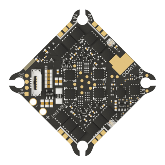
Page 4: Chip Layout
Chip Layout OSD(AT7456E) ELRS(SX1281) ELRS(RX ANT) ELRS(ESP8285) 5.8G(IPX ANT) ELRS(WIFI ANT) 5.8G(PA Chip) Gyro(ICM42688) MCU(F405BGA) 5.8G(RTC6705) 8M BlackBox BEC(5V/2A) Baro(SPL06) WS2812 LED TVS Diode Anti-Voltage Spike ESC MCU(BB21) Micro usb Current sensor 12A Mosfets... -
Page 5: Pad Layout
Pad Layout GND +3.3V BB+ +5V RX2 TX2 Yellow LED: ELRS RX Status Blue LED: VTX Channel ELRS RX ROOT Yellow LED: VTX Band RX(ELRS RX) Red LED: VTX Power TX(ELRS TX) +4.5V VTX Power off/on BAT- (GND) Red LED: FC Power BAT+ (3V-8.7V) Blue LED: Gyro Status SDA SCL... -
Page 6: Wiring Diagram
Wiring Diagram Wiring Diagram SBUS SBUS Caution: O3 unit can only be used with a voltage of 2S. -
Page 7: Receiver Wiring Configuration Diagram
Receiver Wiring Configuration Diagram ELRS(SX128X) ELRS(RX ANT) Built-in ELRS ELRS(ESP8285) ELRS(WIFI ANT) TBS Nano RX Frsky R-XSR SBUS SBUS... -
Page 8: Part4- Receiver Frequency Calibration Steps
Receiver Frequency Calibration Steps The FC quickly turns on and off the power three Open the tool menu on the remote times, with the yellow light flashing twice. controller and select ExpressLRS. TOOLS 01 FrSky GaSuite 02 FrSky SBEC 03 FrSky SxR 04 crossfire 05 ELRS 06 .. -
Page 9: Part5- Adjustment Of Vtx Power And Channels
Adjustment of VTX Power and Channels Turn on the transmitter, THR middle, YAW left, PITCH up, enter the OSD menu. Mode-2 Mode-1 The PITCH moves the cursor up and down, and the ELE right to enter the next item. Now, save and exit. -- FEATURES -- -- TRAMP -- -- MAIN --... -
Page 10: Part7- Troubleshooting Faq
Troubleshooting FAQ Troubleshooting FAQ: : Why does the flight controller get hot when plugged into the computer for tuning ? : The flight controller board has a built-in video transmitter and receiver. When connected with a micro USB cable, it starts working and generates heat, which is a normal phenomenon.
Need help?
Do you have a question about the Goku Versatile F405 5IN1 AIO and is the answer not in the manual?
Questions and answers