
Summary of Contents for MW Fly EM-m
- Page 1 EM-m system use, E-DMA.I02.1 installation and Edition Revision maintenance manual EM-m system use, installation and maintenance manual TRANSLATED FREE DISCLOSURE Page 1 of 99...
- Page 2 Publication of any part of this document without written consent of MWfly is strictly prohibited. This Manual forms part of the EM-m system and must be kept safe. It must accompany the EM-m in case of sale to a new owner. The original document...
- Page 3 Use of technical documentation DESCRIPTION 4.1. The system 4.1. User interface 4.3. Mechanical and electrical characteristics 4.3.1. Dimensions display EM-m 4.3.2 Electrical characteristics of the EM-m display 4.3.3 AUXBOX dimensions 4.3.4 AUXBOX electrical characteristics 4.3.5 AHRS Dimension 4.3.6 Electrical Characteristics AHRS 4.4.
- Page 4 EM-m system use, E-DMA.I02.1 installation and Edition Revision maintenance manual 4.4.7. LED status ECUA 4.4.8. LED status ECUB 4.4.9. LED status “GENERATOR M” 4.4.10. LED status “GENERATOR A” 4.4.11. CHARGE A datum 4.4.12. Unit of measure 4.4.13. Bar graphs (blue-yellow-green-red arc) 4.5.
- Page 5 EM-m system use, E-DMA.I02.1 installation and Edition Revision maintenance manual INSTALLATION 5.1. AUXBOX Instrument EM-m 5.3. AHRS 5.4. Settings and checks 5.4.1. Check functions 5.4.2. Check auxbox module temperature 5.4.3. First flight OPERATING INSTRUCTIONS 6.1. General criteria of use 6.1.1.
- Page 6 2.1. Premise Before using the EM-m, it is necessary to understand all the contents of this manual. In case any passage is difficult to understand or in case of doubts, please contact MWfly or an authorized centre in writing, requesting clarification.
- Page 7 EM-m system use, E-DMA.I02.1 installation and Edition Revision maintenance manual Paragraph Topic The numbering of the contents of the manual consists of an alpha-numeric code that follows the following criterion. 6.1.3. The first number indicates the section. The second number indicates the chapter of each section.
-
Page 8: Identification Data
2.3. Identification Data The serial number of the EM-m control instruments is printed on an indelible label applied to the rear of the instrument and consists of an 8-digit numeric code of the type: YY.WW.NNNN... - Page 9 EM-m system use, E-DMA.I02.1 installation and Edition Revision maintenance manual If the use of a torque wrench is prescribed in the description of the maintenance operations, the corresponding inserts necessary to perform torque tightening must be added to all the tools listed.
-
Page 10: Security Elements
The choice to install and use this EM-m instrument is entirely subject to the discretion and responsibility of the manufacturer, assembler and owner of the aircraft: MWfly cannot guarantee the suitability for use of the product on each specific type of aircraft due to the variety of design and project to which the aircraft themselves are subject;... - Page 11 Write down any operating anomalies in the propeller logbook. Never fly before you have solved the problem and noted the correction in the logbook. To use the EM-m system, strictly comply with all national and local laws and regulations This EM-m system has received .
- Page 12 EM-m system use, E-DMA.I02.1 installation and Edition Revision maintenance manual 3.3. Use of technical documentation The technical documentation and the directives are to be considered the necessary tool for personal training, but they cannot in any way replace an adequate specific instruction, both theoretical and operational.
-
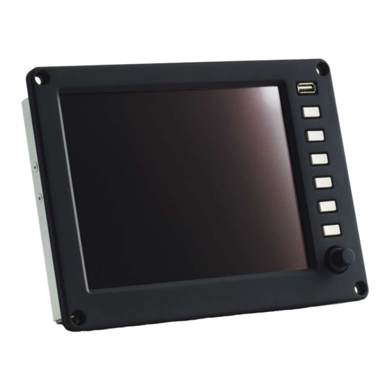
Page 13: User Interface
DESCRIPTION The MW engines of the SPIRIT series can be equipped with the EM-m instrument. The EM-m instrument is an 8” display for viewing engine data. The instrument has been designed to connect directly to the CAN line of the engine control units that are on the MWfly engines receiving the data transmitted by the control units. - Page 14 EM-m system use, E-DMA.I02.1 installation and Edition Revision maintenance manual turn encoder. Also, on the front of the instrument there is a USB socket for downloading the acquisition data or for updating the instrument SW. Display 8” High brightness...
-
Page 15: Mechanical And Electrical Characteristics
Port for data download and SW update 4.1.1.C 4.3. Mechanical and electrical characteristics 4.3.1. Dimensions display EM-m The following drawing shows the dimensions of the instrument, in paragraph 5.2 The dimensions for the cut to be made on the instrument panel for installing the instrument. - Page 16 LTE connection for remote log • Additional independent 32Gb logger Since the EM-m is a panel instrument, all the electrical connections are located on the rear side of the instrument itself. The following connectors are located on the back of the EM-m...
- Page 17 EM-m system use, E-DMA.I02.1 installation and Edition Revision maintenance manual 4.3.3.P name type description POWER DB 9 way male Instrument power supply MAIN DB 15 ways female For connection to the CAN line of the control units and AUXBOX and for the connection of...
- Page 18 EM-m system use, E-DMA.I02.1 installation and Edition Revision maintenance manual 4.3.3 AUXBOX dimensions The AUXBOX is a module that has the following functions: expansion of analogue and digital channels variable pitch propeller control (optional feature) throttle control for helicopter applications (optional feature)
- Page 19 EM-m system use, E-DMA.I02.1 installation and Edition Revision maintenance manual 4.3.3.P the weight of the AUXBOX is 250g. 4.3.4 AUXBOX electrical characteristics The electrical characteristics of the AUXBOX are: 12V power supply (range 9 .. 16 V) max 2.5A ...
- Page 20 Through the information transmitted by the AHRS module, the EM-m instrument is able to determine the quantities that are displayed in the two flight pages (see chapters 4.6 and 4.7).
- Page 21 EM-m system use, E-DMA.I02.1 installation and Edition Revision maintenance manual 4.3.5.P The weight of the AHRS is 90 g. 4.3.6 Electrical Characteristics AHRS The electrical characteristics of the AHRS module are: • 12V power supply (range 9 .. 16 V) max 2.5A •...
- Page 22 EM-m system use, E-DMA.I02.1 installation and Edition Revision maintenance manual 4.4.1.P This page displays the following data (starting from the top right): nome Type of indication Short description Origin of the data numerical value Engine RPM CAN line from ECUA...
- Page 23 EM-m system use, E-DMA.I02.1 installation and Edition Revision maintenance manual + bar graph numerical value Power CAN line from internal CHARGE A + bar graph consumption/recharge CAN module numerical value Real time fuel Calculated data CONS consuption numerical value...
- Page 24 EM-m system use, E-DMA.I02.1 installation and Edition Revision maintenance manual 4.4.2. ROTOR datum The ROTOR datum is optional and is displayed only if it is enabled in the "Tools configuration" page. This datum is typically activated when the instrument is used on helicopters and gyrocopters, to display the rotor speed 4.4.3.
- Page 25 EM-m system use, E-DMA.I02.1 installation and Edition Revision maintenance manual LED STATUS off When switching on the instrument, if the STATUS light is off, it indicates that no anomalies have been recorded in the system or in the use of the engine and therefore it is possible to proceed with starting the engine.
- Page 26 EM-m system use, E-DMA.I02.1 installation and Edition Revision maintenance manual LED STATUS lit red The red status light indicates that an event has occurred for which an engine check must be carried out at an authorized service centre before making another flight.
- Page 27 EM-m system use, E-DMA.I02.1 installation and Edition Revision maintenance manual 4.4.7. LED status ECUA This LED indicates whether control unit A is on (green LED) or off (red LED). In the event of an "ECUA MISSING" error, the LED can no longer give correct information on the status of the control unit.
- Page 28 EM-m system use, E-DMA.I02.1 installation and Edition Revision maintenance manual This instrument indicates the status of the difference between the recharge of the generator and the applied electrical loads. Therefore, the value will be positive if the recharge is greater than the applied electrical loads.
- Page 29 EM-m system use, E-DMA.I02.1 installation and Edition Revision maintenance manual CONS USED FUEL (P) OIL (P) COOLANT 2 °C COOLANT 1 °C °C GEARBOX °C FUEL (T) °C OIL (T) °C 4.4.2.C 4.4.13. Bar graphs (blue-yellow-green-red arc) Each graphic bar is divided into sections with different colours ...
- Page 30 EM-m system use, E-DMA.I02.1 installation and Edition Revision maintenance manual In any case, once landed it is necessary to make a careful inspection of the engine to detect any damage, and in order to understand the causes of the event.
- Page 31 EM-m system use, E-DMA.I02.1 installation and Edition Revision maintenance manual 4.5. Page 2 “diagnostics” 4.5.1.P The data contained in this page is used to diagnose the injection system, verify correct operation and identify any anomalies. This page is reserved for assistance centres. In the event of an engine...
- Page 32 EM-m system use, E-DMA.I02.1 installation and Edition Revision maintenance manual The following table shows the data displayed on the diagnostic page and a brief description data description ECU A ON Elapsed time ECU A ECU B ON Elapsed time ECU B...
- Page 33 EM-m system use, E-DMA.I02.1 installation and Edition Revision maintenance manual INJ 1 (ECUB) ECUB injector 1 control diagnosis INJ 2 (ECUB) ECUB injector 2 control diagnosis INJ 3 (ECUB) ECUB injector 3 control diagnosis INJ 4 (ECUB) ECUB injector 4 control diagnosis 4.5.1.C...
- Page 34 EM-m system use, E-DMA.I02.1 installation and Edition Revision maintenance manual 4.6. Page 3 “flight instrument” 4.6.1.P This page is activated only by enabling the AHRS function and connecting the AHRS module and the GPS to the instrument The data available on this page is:...
- Page 35 EM-m system use, E-DMA.I02.1 installation and Edition Revision maintenance manual the typical air. The QNH is modified using the knob, it is therefore possible to adjust the starting altitude. Ground speed measured with GPS Ground speed Rate of climb (rate of climb or descent)
- Page 36 EM-m system use, E-DMA.I02.1 installation and Edition Revision maintenance manual 4.7. Page 4 “flight instrument + HSI” 4.7.1.P This page is activated only by enabling the AHRS function and connecting the AHRS module and the GPS to the instrument Page four is a split screen page showing flight data on the left and the HSI (Horizontal Situation Indicator) instrument on the right.
- Page 37 EM-m system use, E-DMA.I02.1 installation and Edition Revision maintenance manual The data displayed on the page are indicated in the following table: datum description direction to destination Ground speed (GPS speed) Distance to destination direction set by the pilot...
- Page 38 EM-m system use, E-DMA.I02.1 installation and Edition Revision maintenance manual The following symbols are contained in the CDI tool: This symbol represents the aircraft 4.7.3.P This symbol represents the direction to the destination point 4.7.4.P The bar indicates the direction of the route from the starting point to the destination point 4.7.5.P...
- Page 39 EM-m system use, E-DMA.I02.1 installation and Edition Revision maintenance manual 4.8. Page 5 “system configuration” 4.8.1.P This page presents a menu through which you can configure the system or access other system functions. To scroll the cursor in the menu, turn the knob on the instrument, while to select a menu item, press the knob.
- Page 40 EM-m system use, E-DMA.I02.1 installation and Edition Revision maintenance manual To change the system units (flight pages only) Display system To set the pitch angle of the aircraft (for AHRS) Pitch offset To set the maximum speed of the aircraft (VNE)
- Page 41 EM-m system use, E-DMA.I02.1 installation and Edition Revision maintenance manual 4.8.1. Set volume 4.8.2.P In this page it is possible to set the volume for the alarm warnings, the range goes from 5 to 31 to change the volume level in this page it is necessary to rotate the knob.
- Page 42 EM-m system use, E-DMA.I02.1 installation and Edition Revision maintenance manual 4.8.2 Copy log file 4.8.3.P To be able to download the data from the dashboard, enter this page and follow the procedure below: insert a USB memory key into the USB port...
- Page 43 EM-m system use, E-DMA.I02.1 installation and Edition Revision maintenance manual 4.8.4.P If the mass memory is inserted in the USB port select "YES" with the knob and press the knob, otherwise insert the mass memory, select "YES" and press the...
- Page 44 EM-m system use, E-DMA.I02.1 installation and Edition Revision maintenance manual 4.8.5.P After pressing the knob, the system starts downloading the files into the USB memory, this procedure takes a few seconds at the end of the procedure a message will appear confirming that the...
- Page 45 EM-m system use, E-DMA.I02.1 installation and Edition Revision maintenance manual 4.8.3 Delete log files 4.8.6.P Only service centres are authorized to delete data from the memory, by selecting the Delete log file function. When the free memory drops below 50 Mbyte, the 5 oldest acquisition files are deleted.
- Page 46 EM-m system use, E-DMA.I02.1 installation and Edition Revision maintenance manual 4.8.4 Technical data 4.8.7.P TRANSLATED FREE DISCLOSURE Page 46 of 99...
- Page 47 EM-m system use, E-DMA.I02.1 installation and Edition Revision maintenance manual This page displays the following technical data: nome Descrizione EMS S/N EM-m serial number Motor S/N Engine serial number Software version EM-m SW rersion Firmware user EM-m fW version ECU1 Vbatt V batt.
- Page 48 EM-m system use, E-DMA.I02.1 installation and Edition Revision maintenance manual GPS time GPS-time * GPS date GPS-date * Num of SAT GPS num sat * GPS Fix 0= no Fix, 1=fix, 2 = differential GPS Quality * Internal capacitor status...
- Page 49 EM-m system use, E-DMA.I02.1 installation and Edition Revision maintenance manual 4.8.5 Display system 4.8.8.P In this page the user can select the measurement system: Anglo-Saxon System “Imperial and US customary unit” Metric system "Metric System" The system selection affects only the two flight instrument pages To select, turn the knob, to confirm the selection, press the knob.
- Page 50 EM-m system use, E-DMA.I02.1 installation and Edition Revision maintenance manual 4.8.6 Pitch offset 4.8.9.P Pitch is the pitch angle of the AHRS sensor, to be calibrated to 0° after installation, before calibrating by levelling the aircraft. This page is accessible only with the activation of the AHRS+GPS function To select, rotate the knob, to confirm the selection, press the knob.
- Page 51 EM-m system use, E-DMA.I02.1 installation and Edition Revision maintenance manual 4.8.7 Speed limit 4.8.10.P the "speed limit" is the maximum IAS threshold of the aircraft, also called VNE. When the set threshold is exceeded, the IAS indicator turns red,...
- Page 52 EM-m system use, E-DMA.I02.1 installation and Edition Revision maintenance manual 4.8.8 Destination 4.8.11.P In this page It is possible to enter the coordinates of the destination for the CDI tool described in chapter 4.7 This page is accessible only with the activation of the AHRS+GPS...
- Page 53 EM-m system use, E-DMA.I02.1 installation and Edition Revision maintenance manual 4.8.9 CAN2CAN update 4.8.12.P On this page it is possible to update the data transmission table on the CAN AEROSPACE. The CAN AEROSPACE function is an optional function The update can only be done by authorized personnel or by a MWfly service centre The “CAN2CAN”...
-
Page 54: Tools Configuration
EM-m system use, E-DMA.I02.1 installation and Edition Revision maintenance manual 4.8.10 Tools configuration 4.8.13.P On this page it is possible to configure the system according to the engine and its application and the accessories of the engine itself. This configuration page is only accessible with the engine off. - Page 55 EM-m system use, E-DMA.I02.1 installation and Edition Revision maintenance manual Aux genenerator YES/NO Aux generator Setpoint 1 for VPP Take off RPM Value Setpoint 1 Setpoint 2 for VPP Climb RPM Valore Setpoint 2 Setpoint 3 per controllo VPP...
- Page 56 EM-m system use, E-DMA.I02.1 installation and Edition Revision maintenance manual Select the motor type according to the following table Engine type sceltion note Direct type set RPM bargraph All diredt version Type A set RPM bargraph Spirit 140 PSRU,...
- Page 57 EM-m system use, E-DMA.I02.1 installation and Edition Revision maintenance manual 4.8.15.P select “ON”, the rotor speed bar will automatically appear on page 1 “engine data”. To select, rotate the knob, to confirm the selection, press the knob. Connect the rotor speed sensor as per diagram 5.1.3.P You can select the current indicator display.
- Page 58 EM-m system use, E-DMA.I02.1 installation and Edition Revision maintenance manual From the menu of the “tools configuration” page select “current”. Select "ON" if you want to view this data or "OFF" if you do not want to view this data.
- Page 59 EM-m system use, E-DMA.I02.1 installation and Edition Revision maintenance manual to activate the light, select “ON”. To select, rotate the knob, to confirm the selection, press the knob. If the instrument is used to control the VPP (see engine type configuration) it is possible to program the values of the three setpoints from the "Tool configuration"...
- Page 60 EM-m system use, E-DMA.I02.1 installation and Edition Revision maintenance manual For more information on the meaning of the setpoint, consult the manual "Installation, use and maintenance manual for variable pitch propeller control systems" Confirm the entered value. 4.8.18.P From the menu of the "Tool configuration" page select "setpoint 2”.
- Page 61 EM-m system use, E-DMA.I02.1 installation and Edition Revision maintenance manual 4.8.19.P Enter the value of setpoint 2 (climb RPM value). To modify the value of each box, rotate the knob, to confirm the selected value, press the knob. Once selected, the cursor will...
- Page 62 EM-m system use, E-DMA.I02.1 installation and Edition Revision maintenance manual 4.8.20.P From the menu of the "Tool configuration" page select "setpoint 3”. TRANSLATED FREE DISCLOSURE Page 62 of 99...
- Page 63 EM-m system use, E-DMA.I02.1 installation and Edition Revision maintenance manual 4.8.21.P Enter the value of setpoint 4 (cruise RPM value). To modify the value of each box, rotate the knob, to confirm the selected value, press the knob. Once selected, the cursor will...
- Page 64 EM-m system use, E-DMA.I02.1 installation and Edition Revision maintenance manual 4.8.22.P TRANSLATED FREE DISCLOSURE Page 64 of 99...
- Page 65 EM-m system use, E-DMA.I02.1 installation and Edition Revision maintenance manual 4.8.11 Service 4.8.23.P This page displays the following data: data descriptiom EM-m serial number EMS S/N Engine serial number Engine S/N Total engine time Engine time Elapsed hours from last service...
- Page 66 EM-m system use, E-DMA.I02.1 installation and Edition Revision maintenance manual The "service time" and "status counter" reset function is reserved for MWfly and MWfly authorized service centres The reset of the "service time" will be performed by the MWfly...
- Page 67 EM-m system use, E-DMA.I02.1 installation and Edition Revision maintenance manual 4.8.12 Reserved 4.8.24.P This page is reserved for MWfly and can only be accessed with a password. This page is only accessible with the engine off. TRANSLATED FREE DISCLOSURE...
- Page 68 EM-m system use, E-DMA.I02.1 installation and Edition Revision maintenance manual 4.8.13 file conf 4.8.25.P This page is reserved for MWfly and can only be accessed with a password. This page is only accessible with the engine off. TRANSLATED FREE DISCLOSURE...
- Page 69 EM-m system use, E-DMA.I02.1 installation and Edition Revision maintenance manual 4.8.14 Data time 4.8.26.P In this page it is possible to set UTC time and date. To change the value of each box, turn the knob, to confirm the selected value, press the knob.
- Page 70 EM-m system use, E-DMA.I02.1 installation and Edition Revision maintenance manual 4.8.13 Auxbox update 4.8.27.P From this page it is possible to update the SW of the AUXBOX. This page is reserved for MWfly This page is only accessible with the engine off.
- Page 71 EM-m system use, E-DMA.I02.1 installation and Edition Revision maintenance manual 4.9. Alarm If an alarm condition occurs, it is highlighted in the upper part of the screen on pages 1, 2 and 4 with an error message as shown in the figure. There are two types of alarm: o Major alarm –...
- Page 72 EM-m system use, E-DMA.I02.1 installation and Edition Revision maintenance manual 4.9.1.P The following table shows the list of messages and their meaning of the alarms that appear in the pop-up on the left: message Type of event Note alarm...
- Page 73 EM-m system use, E-DMA.I02.1 installation and Edition Revision maintenance manual arriving from control unit B supply of the control unit or by the (see table 4.4.1C) N/A is interruption of the CAN line of the indicated instead control unit...
- Page 74 EM-m system use, E-DMA.I02.1 installation and Edition Revision maintenance manual SENSOR TEMP The water temperature of This alarm could indicate a bank 1 is below -40°C or broken sensor or wiring or a WATER 1 above 145°C. disconnected sensor.
- Page 75 EM-m system use, E-DMA.I02.1 installation and Edition Revision maintenance manual HIGH The water temperature of Yellow bank 2 exceeds the green TEMPERATURE threshold. WATER 2 HIGH IAT temperature Yellow exceeds green TEMPERATURE threshold. HIGH FUEL fuel temperature Yellow exceeds...
- Page 76 EM-m system use, E-DMA.I02.1 installation and Edition Revision maintenance manual 4.10 VPP Control The system has been designed to also function as a user interface for controlling the pitch of the propeller. To use the instrument as a user interface for controlling the variable pitch propeller, refer to the relative manual 4.11...
- Page 77 EM-m system use, E-DMA.I02.1 installation and Edition Revision maintenance manual IAS [knots] ALT [feet] LATITUDE LONGITUDE GPS SPEED [knots] GPS ALT [feet] NUM SAT I GEN [A] SENS ERR ...
-
Page 78: Installation
The acquisition files can only be deleted by MWfly authorized personnel. INSTALLATION The EM-m instrument is a reliable system, nevertheless, it may happen that a malfunction or breakage can occur even during the flight. It is the user's responsibility to fly safely and install alternative equipment on the aircraft. - Page 79 EM-m system use, E-DMA.I02.1 installation and Edition Revision maintenance manual The A.M.E. s.r.l. provides warranty under the following conditions. If, during the period of two (2) years following the purchase of the instrument, defects in materials or functioning are found, A.M.E. s.r.l.
- Page 80 EM-m system use, E-DMA.I02.1 installation and Edition Revision maintenance manual The AUXBOX module is the module to which the following auxiliary sensors are connected: engine oil pressure sensor fuel pressure sensor fuel temperature sensor MAP sensor (only for SW version dedicated to B22 and B25 series engines) ...
- Page 81 EM-m system use, E-DMA.I02.1 installation and Edition Revision maintenance manual 5.1.2.P Drill [2] in the two foreseen points with the foreseen bit. Insert the fixing screws into the module. Fix the module [3], tightening [4+3] to 4 Nm. In the case of fixing outside the cabin, carry out the checks set out in paragraph 5.4.2.
- Page 82 EM-m system use, E-DMA.I02.1 installation and Edition Revision maintenance manual 5.1.3.P TRANSLATED FREE DISCLOSURE Page 82 of 99...
- Page 83 Instrument EM-m The EM-m instrument is a panel instrument, which must be fixed to the instrument panel of the aircraft by approaching it from the front: in order to fix the instrument, the panel must therefore not be removed.
- Page 84 Edition Revision maintenance manual 5.2.1.P – Dima di foratura EM-m The position must be chosen considering the fact of being able to easily reach the engine speed setting knob and the function selection button during flight. Drill [2] the instrument panel.
- Page 85 EM-m system use, E-DMA.I02.1 installation and Edition Revision maintenance manual 5.2.2.P 5.3. AHRS For correct system operation, the device must be positioned away from magnetic or ferromagnetic parts, power cables and electromagnets, install the sensor on a flat surface following the correct orientation of the aircraft, only pitch errors can be compensated for by calibration.
- Page 86 EM-m system use, E-DMA.I02.1 installation and Edition Revision maintenance manual 5.5.1.P The module must be fixed in the cabin. The module can be fixed either on a plane, oriented as indicated in the following image. TRANSLATED FREE DISCLOSURE Page 86 of 99...
- Page 87 EM-m system use, E-DMA.I02.1 installation and Edition Revision maintenance manual 5.5.2.P Necessary material 1. Pencil 2. 4.5mm drill bit 3. 4 mm Allen key 4. Torque wrench 0-25Nm After choosing the location, mark [1] the drilling points using the template in the following figure.
- Page 88 EM-m system use, E-DMA.I02.1 installation and Edition Revision maintenance manual 5.5.3.P Drill [2] in the two foreseen points with the foreseen bit. Insert the fixing screws into the module. Fix the module [3], tightening [4+3] to 4 Nm. Complete the installation by making the electrical connections referring to the following diagram 5.5.4.P...
- Page 89 EM-m system use, E-DMA.I02.1 installation and Edition Revision maintenance manual Connect the pitot tubes to the pressure inputs 5.4. Settings and checks The following checks relate only to the functions of the system as an EM- m instrument, if it is used as a VPP or electronic throttle control instrument, refer to the checks indicated in the relative manuals.
- Page 90 EM-m system use, E-DMA.I02.1 installation and Edition Revision maintenance manual The check must be carried out immediately after turning off the engine: in fact, after turning off the engine, the temperature of the engine compartment, but, for the purpose of checking the operating temperature of the control module, this is not significant as in this condition the module is off or inactive.
- Page 91 EM-m system use, E-DMA.I02.1 installation and Edition Revision maintenance manual 6. OPERATING INSTRUCTIONS Before fly, it is necessary to check the correct functioning of the system on the ground. If the system is also used to control the pitch of the propeller, follow the safety regulations indicated in the relative manuals.
- Page 92 In order to improve and solve any recurring defects, the user is welcome to communicate any anomalies found and their resolution, or any other consideration that could improve the safety in using the EM-m system or the clarity of the information contained in this manual.
- Page 93 EM-m system use, E-DMA.I02.1 installation and Edition Revision maintenance manual Anomaly Communication Form Name Last name: Phone Number: E-mail Date Prop. model Prop. Serial n. Flight hours Aircraft Aircraft model manufacturer Type of use Mission <1h Mission >1h School...
-
Page 94: Maintenance
EM-m system use, E-DMA.I02.1 installation and Edition Revision maintenance manual 7. MAINTENANCE Any interventions performed with criteria other than those described below can be very dangerous for safety and harmful to the integrity of the system, and should be absolutely avoided. -
Page 95: System Logbook
EM-m system use, E-DMA.I02.1 installation and Edition Revision maintenance manual intensive use (for example piloting schools) or in areas with extreme climates (arid areas or areas with a harsh climate) the intervals should be halved. In addition to these checks, it is necessary to carry out the pre-flight checks specified in paragraph 6.1.2. -
Page 96: Scheduled Maintenance
EM-m system use, E-DMA.I02.1 installation and Edition Revision maintenance manual The following information must be noted in the appropriate spaces in the propeller logbook. Scheduled maintenance interventions Unscheduled maintenance interventions Total or partial revision Adjustments and balances values ... -
Page 97: Unscheduled Maintenance
In the event of failures or non-compliant events during operation of the Em-m system, it is necessary to carry out a thorough check before the next flight.. 7.6.2. Electrocution In the event that, during the flight, there is a suspicion that lightning has struck the aircraft: Land as soon as possible. - Page 98 EM-m system use, E-DMA.I02.1 installation and Edition Revision maintenance manual Check the correct functioning of the instrument and consistency of the data displayed by the instrument. TRANSLATED FREE DISCLOSURE Page 98 of 99...
- Page 99 EM-m system use, E-DMA.I02.1 installation and Edition Revision maintenance manual SIGNATURES LIST REVISIONS DOCUMENT Filled out and checked on from Signature 26/08/2023 Guido FANTINI Approved on Firma 26/08/2023 Stefano MARELLA Rev. Applicability Section Page Date Da #0001 1. Summary...
Need help?
Do you have a question about the EM-m and is the answer not in the manual?
Questions and answers