Table of Contents
Advertisement
Quick Links
Advertisement
Table of Contents

Subscribe to Our Youtube Channel
Summary of Contents for SIMARINE Nereide
- Page 1 ® S I M A R I N E Nereide Light Switch USER MANUAL V1.0...
- Page 2 Nereide Light Switch © 2022 SIMARINE All rights reserved. No parts of this work may be reproduced in any form or by any means - graphic, electronic, or mechanical, including photocopying, recording, taping, or information storage and retrieval systems - without the written permission of the publisher.
-
Page 3: Table Of Contents
Table of contents 1. Introduction 2. Safety 3. Overview 4. About 5. Installation Operation ......................14 Mounting ......................14 Cables ........................ 14 Detailed view ....................15 6. Multiway switching Setting addresses ....................18 Rotary switch ..................... 18 Rotary switch SW6 .................... 19 6.3.1 Table SW6 address positions .............. -
Page 5: Introduction
Introduction... - Page 6 The power source is common for both buttons. Each button independently controls one channel. Width modulation with 400Hz and 12V pulse is implemented for LED dimming. Simarine's SICOM allows the switch to be used in multiple ways, controlling one or more lights from different locations.
-
Page 7: Safety
Safety... - Page 8 2. Safety Only qualified electricians with proper safety equipment should make installation of Simarine electronics. When working with batteries, you should wear protective clothing and eye protection. CAUTION: Do NOT connect anything to a damaged battery. It could heat up, catch fire, or...
-
Page 9: Overview
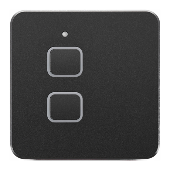
Overview... - Page 10 3. Overview The Nereide Light Swtich comes in two different colors. Black and silver.
-
Page 11: About
About... - Page 12 4. About Short press of the switch 1 or switch 2 - ON/OFF Long press of the switch 1 or switch 2 - Dimmer functionality If you connect 2 channels parallelly, the current limit doubles (10A) If you have two light switches, connected to the other via SiCOM cable, then the second switch doesn't need an additional power source (the second switch has the same address as the first switch)
-
Page 13: Installation
Installation... -
Page 14: Operation
5. Installation Operation The multifunctional switch can be connected in daisy chain to operate in multiway switching. It can operate in three different modes: · PWM mode (Pulse Width Modulation) dimming LED lights. · ON/OFF mode switching 12V ON or 0V OFF on outputs. Both buttons can simultaneously control both outputs (only in PWM and On/Off mode). -
Page 15: Detailed View
· For the SiCOM connection use the supplied cable. Cable length C Cable length Cable type < 5m No limitations >= 5m 2x2x0.25 mm2 twisted pair (recommended) Detailed view J1 – female RJ9 connector - SiCOM communication J2 – female RJ9 connector - SiCOM communication CH1: ·... -
Page 17: Multiway Switching
Multiway switching... -
Page 18: Setting Addresses
6. Multiway switching SiCOM communication standard is implemented to enable the multiway switching. On each switch there are two RJ9 four pin female connectors. Connect one switch with another, to communicate using SiCOM cable with RJ9 male connectors on both ends. The implemented communications standard is RS485 physical layer standard. -
Page 19: Rotary Switch Sw6
The high part is the same for the complete switch. Lower part of the button address is determined with SW6. If two or more switches have to work in the multiway switching, then all of them must have the same high part address –... - Page 20 The complete address for each button is a combination of SW3 address and SW6 address from the table above. When the SW6 rotary switch is in the “F” position, button 1 and button2 have the same address. In this case the communication is not possible or makes no sense while the received message can’t be assigned to the proper button.
-
Page 21: Simultaneously Control Both Outputs
Simultaneously Control Both Outputs... - Page 22 7. Simultaneously Control Both Outputs Note: Factory default is this option is disabled. The multifunctional switch can be set to simultaneously control two outputs with both buttons. This is possible only in the PWM and ON/OFF mode. When one button is pressed, both outputs are ON or OFF or when one button is continuously pressed, the dimming starts on both outputs.
-
Page 23: Setup Modes Of Operation
Setup modes of operation... -
Page 24: Setup Procedure
8. Setup modes of operation Factory default mode is the PWM mode. To select ON/OFF or Push Button mode, the switch has to be setup. The best time to change the mode is right before the installation When one or both buttons are in setup mode the RGB colour LED around the button will flash. -
Page 27: Saving Light Status
Saving light status... - Page 28 9. Saving light status Factory default in this option is disabled. The multifunctional switch can be enabled to save states of outputs (ON/OFF, dimming index) in non-volatile memory. This option can be enabled with SW5. The status of the switch is saved 6 seconds after any changes on outputs.
-
Page 29: Technical Specifications
Technical specifications... - Page 30 10. Technical specifications Operating Voltage range 8 - 16VDC Outputs Maximum load (Amps per output) Power consumption Power OFF Power ON, no load on outputs 3mA to 20mA. Depends on the environment light. Over the day RGB LEDS are shining brighter than in the night. PWM - Pulse Width Modulation 12V, 400Hz (Default)
- Page 31 Safe Voyage.
Need help?
Do you have a question about the Nereide and is the answer not in the manual?
Questions and answers