Table of Contents
Advertisement
Quick Links
48EZ(N)
Single- -Packaged Gas Heating/Electric Heat Pump
System with Puronr (R- -410A) Refrigerant
Single- - And Three- -Phase Units Sizes 024- -060
NOTE:
Read the entire instruction manual before starting the
installation.
NOTE:
Installer: Make sure the Owner's Manual and Service
Instructions are left with the unit after installation.
TABLE OF CONTENTS
. . . . . . . . . . . . . . . . . . . . . . . . . . . . . . . . . .
. . . . . . . . . . . . . . . . . . . . . . . . . . . . . . . . .
. . . . . . . . . . . . . . . . . . . . . . . . . . . . . . . . . . .
. . . . . . . . . . . . . . . . . . . . . . . . . . . . . . . .
. . . . . . . . . . . . . . . . . . . . . . . . . . . . . .
. . . . . . . . . . . . . . . . . . . . . . . . . . . . . . . . . . . . .
. . . . . . . . . . . . . . . . . . . . . . . . . . . . . . . . . . . .
. . . . . . . . . . . . . . . . . . . . . . . . . . . . . . . . .
. . . . . . . . . . . . . . . . . . . . . . . . . . .
. . . . . . . . . . . . . . . . . . . . . . . . . . . . . . . .
. . . . . . . . . . . . . . . . . . . . . . . . . . . . . . . .
. . . . . . . . . . . . . . . . . . . . . . . . . . . . . . . . . .
Install Gas Piping
. . . . . . . . . . . . . . . . . . . . . . . . . . . . . .
. . . . . . . . . . . . . . . . . . . . . . . . . . .
. . . . . . . . . . . . . . . . . . . . . . . . . . . . . . . . . . . .
Balance Point Setting Thermidistat or Hybrid Heat
. . . . . . . . . . . . . . . . . . . . . . . . . . . . . . . . . . .
. . . . . . . . . . . . . . . . . . . . . . . . . . . . . . .
. . . . . . . . . . . . . . . . . . . . . . . . . .
. . . . . . . . . . . . . . . . . . . . . . . . . . . . . . . . . .
. . . . . . . . . . . . . . . . . . . . . . . . . . . . . . . . . . . .
. . . . . . . . . . . . . . . . . . . . . . . . . . . . . . .
. . . . . . . . . . . . . . . . . . . . . . . . . . . . . . .
. . . . . . . . . . . . . . . . . . . . . . . . . . . .
. . . . . . . . . . . . . . . . . . . . . . . . . . . . . . .
. . . . . . . . . . . . . . . . . . . . . . . . . . . . . . . . . . . . . . .
. . . . . . . . . . . . . . . . . . . . . . . . . .
. . . . . . . . . . . . . . . . . . . . . . . . . . . . .
. . . . . . . . . . . . . . . . . . . . . . . . . . .
. . . . . . . . . . . . . . . . . . . . . . . . . . . . . . . . . . . .
. . . . . . . . . . . . . . . . . . . . . . . . . . . . . . . . . .
. . . . . . . . . . . . . . . . . . . . . . . . . . . . . . . . . . .
Installation Instructions
PAGE
. . . . . . . . . . . . . . . . . . . . . . . .
. . . . . . . . . . . . . . . .
. . . . . . . . . . . . . . . . . . . . . . . . . .
. . . . . . . . . . . . . . . . . . . . . . .
. . . . . . . . . . . . . . . . . . . . . . .
. . . . . . . . . . . . .
. . . . . . . . . . . . . . . . . . . . . .
12- -14
15- -19
. . . . . . . . . . . . . . . . . . . . . . . .
. . . . . . . . . . . . . . . . . . . . . . . .
. . . . . . . . . . . . . .
. . . . . . . . . . . . . . . . . . . . . . . .
. . . . . . . . . . . . . .
. . . . . . . . . . . . . . .
. . . . . . . . . . . . . . . .
. . . . . . . . . . . .
23- -26
. . . . .
1
2
2- -13
2
2
2
2
2
2
2
2
2
7
7
7
8- -10
10
10
11
11
. . . . . . . . . . . . . . . . . . . . . . . . . . . . . . . . . . . . . . .
11
12
12
15
SAFETY CONSIDERATIONS
15
Installation and servicing of this equipment can be hazardous due
15
to mechanical and electrical components. Only trained and
qualified personnel should install, repair, or service this
16
equipment.
16
16
Untrained personnel can perform basic maintenance functions
16
such as cleaning and replacing air filters. All other operations
17
must be performed by trained service personnel. When working
17
on this equipment, observe precautions in the literature, on tags,
18
and on labels attached to or shipped with the unit and other safety
18
precautions that may apply.
18
Follow all safety codes. Installation must be in compliance with
19
local and national building codes. Wear safety glasses, protective
clothing, and work gloves. Have fire extinguisher available. Read
23
these instructions thoroughly and follow all warnings or cautions
23
included in literature and attached to the unit.
24
Recognize safety information. This is the safety- -alert symbol
24
24
When you see this symbol on the unit and in instructions or
manuals, be alert to the potential for personal injury. Understand
24
these signal words: DANGER, WARNING, and CAUTION.
24
These words are used with the safety- -alert symbol. DANGER
25
1
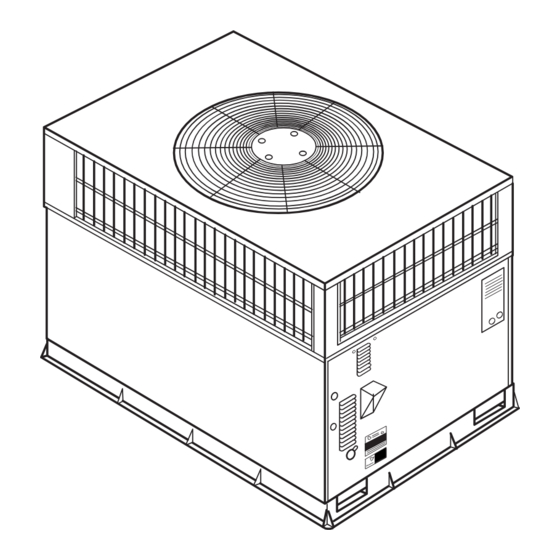
Fig. 1 - - Unit 48EZ
. . . . . . . . . . . . . . . . . . . . . . . . . . . . . . . . . . . .
. . . . . . . . . . . . . . . . . . . . . .
. . . . . . . . . . . . . . . . . . . . . . . . . . . . . . . .
. . . . . . . . . . . . . . . . . . . . . . . . . . . . . . . . . .
. . . . . . . . . . . . . . . . . . . . . . . . . .
. . . . . . . . . . . . . . . . . . . . . . . . . . . . . . . . . . .
. . . . . . . . . . . . . . . . . . . . . . . . . . . . .
. . . . . . . . . . . . . . . . . . . . . . . . . . .
A99338
25
25
25
26
26
26
26
29
29
.
Advertisement
Table of Contents

Related Manuals for Carrier 48EZN


Summary of Contents for Carrier 48EZN
-
Page 1: Table Of Contents
48EZ(N) Single- -Packaged Gas Heating/Electric Heat Pump System with Puronr (R- -410A) Refrigerant Single- - And Three- -Phase Units Sizes 024- -060 Installation Instructions NOTE: Read the entire instruction manual before starting the installation. NOTE: Installer: Make sure the Owner’s Manual and Service Instructions are left with the unit after installation. -
Page 2: Introduction
identifies the most serious hazards which will result in severe per- ROOF CURB sonal injury or death. WARNING signifies hazards which could Install accessory roof curb in accordance with instructions result in personal injury or death. CAUTION is used to identify shipped with curb (See Fig. - Page 3 REQUIRED CLEARANCE TO COMBUSTIBLE MATL. REQUIRED CLEARANCE FOR OPERATION AND SERVICING INCHES [mm] (R efer to M aximum O perating C learances ) INCHES [mm] EVAP. COIL ACCESS SIDE............36.00 [914.0] TOP OF UNIT...................14.00 [355.6] POWER ENTRY SIDE..............42.00 [1066.8] (EXCEPT FOR NEC REQUIREMENTS) DUCT SIDE OF UNIT.................2.00 [50.8] UNIT TOP ..................48.00 [1219.2] SIDE OPPOSITE DUCTS ..............14.00 [355.6]...
- Page 4 REQUIRED CLEARANCE TO COMBUSTIBLE MATL. REQUIRED CLEARANCE FOR OPERATION AND SERVICING INCHES [mm] INCHES [mm] TOP OF UNIT...................14.00 [355.6] EVAP. COIL ACCESS SIDE............36.00 [914.0] DUCT SIDE OF UNIT.................2.00 [50.8] POWER ENTRY SIDE..............42.00 [1066.8] SIDE OPPOSITE DUCTS ..............14.00 [355.6] (EXCEPT FOR NEC REQUIREMENTS) BOTTOM OF UNIT ................0.50 [12.7] UNIT TOP ..................48.00 [1219.2] ELECTRIC HEAT PANEL ..............36.00 [914.4]...
- Page 5 HVAC unit HVAC unit base base Gask eting inner flange* Scre w Scre w Gask eting (NO TE A) (NO TE A) inner flange* *Gask eting *Gask eting outer flange outer flange Wood nailer* Wood nailer* Flashing field Flashing field supplied supplied Roofcurb*...
- Page 6 A07216 CORNER WEIGHTS (SMALL CABINET) CORNER WEIGHTS (LARGE CABINET) Unit Unit Unit Total Weight Total Weight Corner Corner Weight 1 Weight 1 Corner Corner Weight 2 Weight 2 Corner Corner Weight 3 Weight 3 Corner Corner Weight 4 Weight 4 Shipping Shipping Weight...
-
Page 7: Rig And Place Unit
Step 5 — Rig and Place Unit groundlevel installations. Install a field- -supplied condensate trap at end of condensate connection to ensure proper drainage. Make WARNING sure that the outlet of the trap is at least 1 in. lower than the drain- -pan condensate connection to prevent the pan from overflowing (See Fig. - Page 8 Table 1 – Physical Data - - Unit 48EZ UNIT SIZE 48EZ 024040 030040 030060 036060 036090 042060 042090 NOMINAL CAPACITY --- ton 2 ---1/2 2 ---1/2 3 ---1/2 3 ---1/2 OPERATING WEIGHT --- lb. OPERATING WEIGHT --- kg COMPRESSORS Scroll Quantity REFRIGERANT (R --- 410A)
- Page 9 Table 1 - - Physical Data - - Unit 48EZ (Cont’d) UNIT SIZE 48EZ 048090 048115 048130 060090 060115 060130 NOMINAL CAPACITY --- ton OPERATING WEIGHT--- (lb OPERATING WEIGHT--- kg COMPRESSORS Scroll Quantity REFRIGERANT (R --- 410A) Quantity --- lb 11.5 11.5 11.5...
-
Page 10: Install Duct Connections
4. Install sediment trap in riser leading to heating section 2. Remove horizontal (metal) duct covers to access vertical (See Fig. 8). This drip leg functions as a trap for dirt and (downflow) discharge duct knockouts in unit base. condensate. 3. -
Page 11: Install Electrical Connections
6. Adequately insulate and weatherproof all ductwork and low- -voltage entry points are used (See Fig. 2 and 3 for located outdoors. Insulate ducts passing through acceptable location). unconditioned space, and use vapor barrier in accordance See unit wiring label and Fig. 10 for reference when making high with latest issue of Sheet Metal and Air Conditioning voltage connections. -
Page 12: Control Voltage Connections
minutes), then the gas furnace will come on to satisfy the indoor WARNING temperature demand. If the outdoor temperature is below the “balance point”, the heat pump will not be allowed to operate (i.e. locked out), and the gas furnace will be used to satisfy the indoor ELECTRICAL SHOCK HAZARD temperature. -
Page 13: Easy Selectt
Balance Point Worksheet Based on Entering Indoor Air of 70 Deg. F and Rated CFM Outdoor Air Temp (Deg F) C03008 Balance Point Worksheet 9 PIN CONNECTOR e. ON/OFF DELAY- - SELECT DESIREDTIME DELAY PROFILE ICM PRINTED CIRCUIT BOARD Four motor operation delay profiles are provided to customize and enhance system operation (See Fig. - Page 14 5- -amp automotive fuse placed in series with the installation instructions for Super Dehumidify transformer SEC2 and the R circuit. The C circuit of operation. the transformer is referenced to chassis ground through ACCESSORY INSTALLATION a printed circuit run at SEC1 connected to metal a.
-
Page 15: Transformer Protection
jumper J1 and wire in a standard humidistat (See Fig. d. Inspect all field- - and factory- -wiring connections. Be 14). sure that connections are completed and tight. e. DEHUMIDIFY AND SUPER DEHUMIDIFY e. Inspect coil fins. If damaged during shipping and CAPABILITIES handling, carefully straighten fins with a fin comb. -
Page 16: Unit Sequence Of Operation
Step 2 — UNIT SEQUENCE OF OPERATION the hall- -effect sensor on the induced- -draft motor senses that it has reached the required speed, the 48EZ Sequence of Operation burner sequence begins. This function is a. CONTINUOUS FAN performed by the integrated gas control (IGC). (1.) Thermostat closes circuit R to G- -The Blower (2.) The indoor- -fan motor is energized 45 sec. -
Page 17: Adjust Gas Input
S When the gas supply being used has a different heating value 6. Multiply result of Step 5 by Btu heating value of gas to obtain total measured input in Btuh. Compare this value or specific gravity, refer to national and local codes, or contact with heating input shown in Table 3 (Consult the local gas your distributor to determine the required orifice size. -
Page 18: Start- -Up Cooling And Make Adjustments
CHECKING COOLING CONTROL OPERATION BURNER FLAME Start and check the unit for proper cooling control operation as follows: 1. Place room thermostat SYSTEM switch in OFF position. BURNER Observe that blower motor starts when FAN switch is placed in ON position and shuts down when FAN switch is placed in AUTO position. -
Page 19: Indoor Airflow And Airflow Adjustments
Table 5 – LED Indications ERROR CODE LED INDICATION Normal Operation Hardware Failure Fan On/Off Delay Modified 1 Flash Limit Switch Fault 2 Flashes Flame Sense Fault 3 Flashes Four Consecutive Limit Switch Faults 4 Flashes Ignition Lockout Fault 5 Flashes Induced- - Draft Motor Fault 6 Flashes 7 Flashes... - Page 20 A07202 Fig. 18 - - 208/230- -1- -60 Wiring Diagram, Unit 48EZ...
- Page 21 A07203 Fig. 19 - - 208/230- -3- -60 Wiring Diagram, Unit 48EZ...
- Page 22 Table 9 – 48EZ Gas Heating ECM Airflow Small Cabinet EASY SELECTt BOARD SETTING 1100 1250 (CFM) External Static Unit Pressure 0.0–0.4 0.4–0.7 0.7–1.0 0.0–0.4 0.4–0.7 0.7–1.0 0.0–0.4 0.4–0.7 0.7–1.0 0.0–0.4 0.4–0.7 0.7–1.0 Size (in. wc) Gas Heat Size – –...
-
Page 23: Maintenance
MAINTENANCE 5. Check and inspect heating section before each heating season. Clean and adjust when necessary. To ensure continuing high performance and to minimize the 6. Check flue hood and remove any obstructions, if possibility of premature equipment failure, periodic maintenance necessary. -
Page 24: Flue Gas Passageways
LIMIT SWITCH INDUCED DRAFT MOTOR MOUNT Remove unit access panel. Limit switch is located on the blower partition. BURNER IGNITION Unit is equipped with a direct spark ignition 100 percent lockout system. Ignition module is located in the control box. Module contains a self- -diagnostic LED. -
Page 25: Outdoor Fan
OUTDOOR FAN CAUTION BLOWER HOUSING UNIT OPERATION HAZARD Failure to follow this caution may result in damage to unit components. Keep the outdoor fan free from all obstructions to ensure proper cooling operation. Never place articles on top of the unit. -
Page 26: Gas Input
CESO130076–00 Speedup Quiet Defrost interval Pins Shift DIP switches A99442 Fig. 26 - - Defrost Control If no refrigerant leaks are found and low cooling performance is maintains a constant superheat at the indoor coil exit (cooling suspected, refer to the Checking and Adjusting Refrigerant mode) resulting in higher overall system efficiency. - Page 27 C99097 Fig. 27 - - Refrigerant Circuit HIGH- -PRESSURE SWITCH WARNING The high- -pressure switch is located in the discharge line and protects against excessive condenser coil pressure. It opens at 610 EXPLOSION HAZARD psig. High pressure may be caused by a dirty outdoor coil, failed fan Failure to follow this warning could result in personal injury motor, or outdoor air recirculation.
- Page 28 INDOOR COIL OUTDOOR COIL TXV in Metering Position HP S Bypass LEGEND Position HPS – High Pressure Switch LCS – Loss of Charge Switch Accurater Metering De vice ® Arrow indicates direction of flo w C03011 Fig. 28 - - Typical Heat Pump Operation, Cooling Mode INDOOR COIL OUTDOOR COIL TXV in Bypass...
-
Page 29: Troubleshooting
SERVICING SYSTEMS ON ROOFS WITH SYNTHETIC- LIQUID LINE FILTER DRIER MATERIALS This filter drier is specifically designed to operate with Puron. Use only factory- -authorized components. Filter drier must be POE (polyolester) compressor lubricants are known to cause long replaced whenever the refrigerant system is opened. When term damage to some synthetic roofing materials. - Page 30 PURONR (R- -410A) QUICK REFERENCE GUIDE Puron refrigerant operates at 50- -70 percent higher pressures than R- -22. Be sure that servicing equipment and replacement components are designed to operate with Puron Puron refrigerant cylinders are rose colored. Recovery cylinder service pressure rating must be 400 psig, DOT 4BA400 or DOT BW400. Puron systems should be charged with liquid refrigerant.
- Page 31 Table 12 – Troubleshooting Guide - - Cooling or Heat Pump Heating Mode SYMPTOM CAUSE REMEDY Power Failure Call power company. Fuse blown or circuit breaker tripped Replace fuse or reset circuit breaker. Defective thermostat, contactor, transformer, or control Compressor and Outdoor fan will not Replace component.
- Page 32 Table 13 – Troubleshooting Guide - - Gas Heating SYMPTOM CAUSE REMEDY Water in gas line Drain. Install drip leg. No power to furnace Check power supply fuses, wiring, or circuit breaker. Check transformer. NOTE: Some transformers have internal over ---current protection that No 24 ---v power supply to control circuit requires a cool ---down period to reset.
- Page 33 START-UP CHECKLIST (Remove and Store in Job File) I. Preliminary Information MODEL NO.:_________________________________ SERIAL NO.:__________________________________ DATE:_______________________________________ TECHNICIAN:_________________________________ II. PRE-START-UP (Insert checkmark in box as each item is completed) ( ) VERIFY THAT ALL PACKING MATERIALS HAVE BEEN REMOVED FROM UNIT ( ) REMOVE ALL SHIPPING HOLD DOWN BOLTS AND BRACKETS PER INSTALLATION INSTRUCTIONS ( ) CHECK ALL ELECTRICAL CONNECTIONS AND TERMINALS FOR TIGHTNESS ( ) CHECK GAS PIPING FOR LEAKS (WHERE APPLICABLE)
- Page 34 Catalog No: 48EZ---1SI Printed in U.S.A. Edition Date: 03/07 Copyright 2007 Carrier Corp. S 7310 W. Morris St. S Indianapolis, IN 46231 Replaces: NEW Manufacturer reserves the right to change, at any time, specifications and designs without notice and without obligations.
Need help?
Do you have a question about the 48EZN and is the answer not in the manual?
Questions and answers