Advertisement
Quick Links
Advertisement

Summary of Contents for DIGITAL FORECAST Bridge RS16x16
- Page 1 Digital Forecast Bridge”RS 16*16 HD/SD/3G SDI Matrix Router Instruction Manual...
-
Page 2: Table Of Contents
Contents Caution......................4 Feature......................6 Name and function..................7 Way of use....................8 Signal characteristic..................9 Specification....................11 Attach......................12 www.dfcast.co.kr... - Page 3 Copyright in this user manual DIGITAL FORECAST INC. . Unauthorized reproduction is prohibited that the contents of this manual in whole or part without the prior written consent. Warranty The product is warranted by DIGITAL FORECAST INC. against product defects for a limited warranty period of one (1) year as the date of supplied.
-
Page 4: Caution
symbol indicates a danger. product have high voltage that can cause concern to body electrical shock. DANGER symbol indicates a danger. If do not attention to handling, concerns of personal injury DANGER can result. Do not ignore the DANGER mark and treat them. WARNING symbol indicates a warning. -
Page 5: Feature
Bridge RS 16x16 Bridge RS 16x16 is supporting 8x8 SDI input/output of video as "Routing Switcher". A this model recognizes SD,HD and 3Gb/s SDI signal automatically change, It has the dual power supply and Reclocking function built-in. And input state display. APC function(Control by RS422 communication of PC), button Lock function for the convenience of the user. -
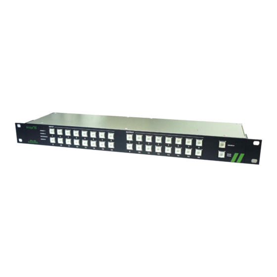
Page 6: Name And Function
2. Name and function 1. LED 2. INPUT 3. OUTPUT 4. ENABLE 5. FUNCTION 그림 전면부 1. LED : POWER1, POWER 2, REFERENCE, REMOTE POWER1 : : Power supply input status of Power1 is shown. POWER2 : Power supply input status of Power2 is shown. . REFERENCE : Reference input status is shown. -
Page 7: Way Of Use
3. Way of use Input / Output Setting To connect the Video source to the INPUT BNC. To connect the OUTPUT BNC to the input of the equipment that I want try to send the display equipment and source . The ON cases the ENABLE button, press the ENABLE button for more than 1 second . -
Page 8: Signal Characteristic
4. Signal Characterisitic HD-SDI Properties HD-SDI Serial Digital Video Connector 75Ω BNC Signal level 800mV ± 10% DC offset 0V ± 0.5V Rise and fall time < 270ps (20% to 80% amplitude) Overshoot <10% of amplitude Timing Jitter <1 UI Alignment Jitter <0.2UI www.dfcast.co.kr... - Page 9 SD-SDI Properties SD-SDI Serial Digital Video Connector 75Ω BNC Signal level 800mV ± 10% DC offset 0V ± 0.5V Rise and fall time 400~800ps(20% to 80% amplitude) Overshoot <10% of amplitude Timing Jitter <0.2 UI Alignment Jitter <0.2UI www.dfcast.co.kr...
-
Page 10: Specification
5. Specification Connections SDI Video Input SD/HD-SDI, 3Gb/s SDI and ASI. X16 (BNC) SDI Video Output SD/HD-SDI, 3Gb/s SDI and ASI with SDI re-clocking. X16 (BNC) Remote Control RS-422 (RJ45) Reference Input B.B , TRI x1 (BNC) TCP/IP (RJ45) Electrical Voltage 90 ~ 240V AC 50/60Hz Power... -
Page 11: Attach
6. Attach Cable connection ※ It consists of PIN MAP like the top, when connecting with RCP, you should manufacture a LAN cable by 1:1 ※ When ENABLE is, the main body can't make ENABLE RCP. If the main body will be ENABLE even if RCP ENABLE will be, RCP will be a disable. ※...
Need help?
Do you have a question about the Bridge RS16x16 and is the answer not in the manual?
Questions and answers