Advertisement
Quick Links
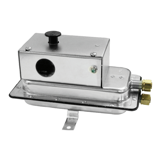
Cleveland Controls
Division of UniControl Inc.
Manual Reset DPDT Air Pressure Sensing Switch for 120 VAC Applications
APPLICATION
The Model AFS-460–136 is a general pur-
pose airflow proving switch designed for
120 VAC HVAC and Energy Management
applications where a manual reset switch
with DPDT contacts is desirable. It may be
used to sense positive, negative, or differ-
ential air pressure.
GENERAL DESCRIPTION &
OPERATION
The plated housing contains a diaphragm, a
calibration spring, a snap-acting switch with
manual reset button, and a dpdt relay.
The sample connections located on each
side of the diaphragm accept .25" OD tub-
ing via the integral compression ferrule and
nut.
An enclosure cover guards against acci-
dental contact with the live switch terminal
screws and the set point adjusting screw.
The enclosure cover will accept a 0.5" con-
duit connection. The manual reset button is
located on the top surface of the enclosure
cover.
MOUNTING (SEE FIGURE 1)
Select a mounting location which is free
from vibration. The AFS-460–136 must be
mounted with the diaphragm in any vertical
plane in order to obtain the lowest specified
operating set point. Avoid mounting with the
(Figure 1)
Cleveland Controls
DIVISION OF UNICONTROL INC.
1111 Brookpark Rd
Cleveland OH 44109
Bulletin LTAFS460136-05
sample line connections in the "up" position.
Surface mount via the two
3
holes in the integral mounting bracket. The
mounting holes are 3-
7
/
" apart.
8
AIR SAMPLING
CONNECTION
(SEE FIGURE 2)
The AFS-460–136 is designed to accept
firm-wall sample lines of ¼" OD tubing by
means of ferrule and nut compression con-
nections. An optional ¼" adapter, suitable
for slip-on flexible tubing is available. For
sample lines of up to 10 feet, ¼" OD tubing
is acceptable. For lines up to 20 feet, use ¼"
ID tubing. For lines up to 60 feet, use ½" ID
tubing. Locate the sampling probe a mini-
mum of 1.5 duct diameters downstream from
the air source. Install the sampling probe as
close to the center of the airstream as pos-
sible. Refer to Figure 2 to identify the high
pressure inlet (H), and the low pressure inlet
(L). Select one of the five application options
listed below, and connect the sample lines
as recommended.
Email:saleshvac@unicontrolinc.com
Web page: http://www.clevelandcontrols.com
AFS–460–136
POSITIVE PRESSURE ONLY:
/
" diameter
the sample line to inlet H; inlet L remains
16
open to the atmosphere.
NEGATIVE PRESSURE ONLY: Connect
the sample line to inlet L; inlet H remains
open to the atmosphere.
TWO NEGATIVE SAMPLES: Connect the
higher negative sample to inlet L. Connect
the lower negative sample to inlet H.
TWO POSITIVE SAMPLES: Connect the
higher positive sample to inlet H. Connect
the lower positive sample to inlet L.
ONE POSITIVE AND ONE NEGATIVE
SAMPLE: Connect the positive sample
to inlet H. Connect the negative sample
to inlet L.
(Figure 2)
Tel: 216-398-0330
Fax: 216-398-8558
Model
Connect
Are you
reading a FAX
or a COPY of this
bulletin? DOWNLOAD
the full-color PDF ver-
sion of this and other
literature at our
website!
Advertisement

Related Manuals for UniControl Cleveland Controls AFS-460 136


Summary of Contents for UniControl Cleveland Controls AFS-460 136
- Page 1 Model Cleveland Controls Division of UniControl Inc. AFS–460–136 Manual Reset DPDT Air Pressure Sensing Switch for 120 VAC Applications APPLICATION The Model AFS-460–136 is a general pur- pose airflow proving switch designed for 120 VAC HVAC and Energy Management applications where a manual reset switch with DPDT contacts is desirable.
- Page 2 ELECTRICAL CONNECTIONS FIELD ADJUSTMENT SPECIFICATIONS (SEE FIGURE 3) The AFS-460–136 Manual Reset Air Switch Before pressure is applied to the diaphragm, Model AFS–460–136 Air Pressure has an adjustment range of 0.40 to 12.0" the snap switch contacts will be in the nor- Sensing Switch w.c., ±.06"...
Need help?
Do you have a question about the Cleveland Controls AFS-460 136 and is the answer not in the manual?
Questions and answers