Table of Contents
Advertisement
Quick Links
Advertisement
Table of Contents

Summary of Contents for OPTO-EDU A50.7043
- Page 1 A50.7043 Thermal Evaporation Carbon Coater Instruction Manual...
-
Page 2: Table Of Contents
Content I. Safety Hints ........................... 1 II. Overview ............................2 2.1 Introduction ......................... 2 2.2 Index Parameters ......................... 2 III. Composition ..........................3 3.1 Appearance of the Mainframe and Its Components ............3 3.2 Appearance and Composition of Vacuum Pump ..............3 3.3 Connecting Pipe Line ...................... - Page 3 5.2 Instrument Operation Flow ....................11 5.3 Installation and Replacement of Evaporation Source ............12 VI. Matters Needing Attention ......................13 VII. Instrument Maintenance ......................14 VIII. Common Faults and Solutions ....................14...
-
Page 4: Safety Hints
I. Safety Hints Danger For special instruments, it is forbidden for non-professionals to disassemble the Danger mainframe Danger In the course of work, the installation part of the evaporation source will produce Danger high temperature, please do not touch it. Danger When changing the evaporation source, taking out or changing the sample, pay Danger... -
Page 5: Overview
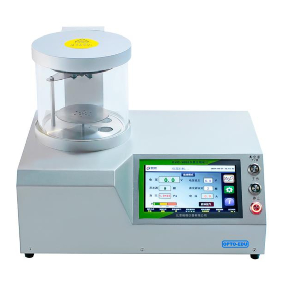
II. Overview 2.1 Introduction A50.7043 Thermal Evaporation Carbon Plating Instrument is a sample pretreatment instrument, which is mainly used in sample preparation of analytical instruments such as scanning electron microscope and electron probe, and can also be used in other fields that require carbon film plating. -
Page 6: Composition
III. Composition A50.7043 Thermal Evaporation Carbon Plating Instrument is mainly composed of mainframe, vacuum pump and connecting pipeline. 3.1 Appearance of the Mainframe and Its Components Upper cover Electrode column Glass cavity Sealing plate Main Switch Heat insulation baffle Total power interface... -
Page 7: Brief Introduction Of Functions
3.4 Brief Introduction of Functions 3.4.1 Mainframe The mainframe is the core component of the instrument, including electrode, evaporation source, baffle, sample table, vacuum chamber, drive circuit, control circuit, Pirani vacuum gauge, display screen, etc. 3.4.2 Function of Vacuum Pump Provide the required vacuum for the system. -
Page 8: 1Parameter Settings
4.1.1Parameter Settings ⚫ Voltage setting (pulse and continuous mode): 0-12V continuously adjustable, step 0.1V; pulse mode defaults to 8V, continuous mode defaults to 6V; ⚫ Pulse number setting (pulse mode): 1-999 continuously adjustable, step 1; ⚫ Evaporation source setting (continuous mode): 1-4 evaporation sources can be set. 4.1.2 Information Hint ⚫... -
Page 9: System Setting Interface
the coating thickness of the sample. If the module is selected, and the film thickness control mode is adopted, "yes" is displayed, and "no" is displayed in other states; ⚫ Running time: the cumulative running time of the equipment is automatically recorded by turning on the total power supply. - Page 10 ⚫ Evaporation Source Degassing-Degassing Time When the evaporation source begins to heat, a certain amount of gas will be released from the surface, which may contaminate the sample or cause vacuum instability. Degassing in advance can eliminate this effect. Select "Yes" and the evaporation source will be preheated and degassed after starting work, and the baffle (see 3.1) will rotate automatically to block the evaporation source and prevent contamination of the sample.
-
Page 11: Advanced Setting
⚫ System Time The system time is not adjusted on time. Set the format as 20XX (year)-XX (month)-XX (day) XX (hours)-XX (minutes)-XX (seconds). 4.3 Advanced Setting The parameters in the advanced settings have been set before the instrument leaves the factory, and users generally do not need to set them. -
Page 12: Installation And Operation
vacuum overshoot" value. This setting improves the adaptability of the system, because in most cases, the vacuum of the system will quickly drop below the "vacuum setting" setting. ⚫ Degassing voltage: the voltage of the evaporation source during degassing, set in the range of 0- 10V;... -
Page 13: Pipeline Connection
注油塞;进气口;出气口;A 向;放油塞;A 向视图;建议加油位置;最高油位线;最低油位 线 Fuel injection plug; air inlet; air outlet; A direction; drain plug; A-direction view; recommended refueling position; highest oil level line; lowest oil level line 3) Tighten the filling plug 5.1.2 Pipeline Connection 1) Install the oil mist filter on the vacuum pump outlet with the clamp provided by the vacuum pump (note that the arrow on the filter label is facing down);... -
Page 14: Circuit Connection
5.1.3 Circuit Connection 1) Insert the power plug of the vacuum pump into the three-core socket on the back of the mainframe (see 3.1); 2) Plug the power cord into the main power connector on the back of the host (see 3.1) and connect it to the power supply (input voltage: 220V/50Hz);... -
Page 15: Installation And Replacement Of Evaporation Source
seamless; 7) Press the vacuum pump on / off entity key: ✓ When the vacuum pump starts to work, the vacuum chamber is vacuumed, and the vacuum degree decreases gradually; ✓ The system automatically detects the status of the evaporation source and displays it in the system status bar at the bottom of the main interface (4.1.4);... -
Page 16: Matters Needing Attention
evaporation source. 2. Install the new evaporation source in the "V" shape as shown below: 1) Firstly, tighten the screws at terminal 1 to tighten the evaporation source slightly, and then tighten the screws at terminal 4. 2) Secondly, tighten the screws at terminal 2 to tighten the evaporation source slightly, and then tighten the screws at terminal 3. -
Page 17: Instrument Maintenance
the vacuum pump to check the tightness of the system. 5. Be careful when changing the sample or evaporation source and wait for the parts to cool before starting the operation to prevent scalding. 6. Do not touch the display screen with sharp objects to avoid damage. VII.
Need help?
Do you have a question about the A50.7043 and is the answer not in the manual?
Questions and answers