
Summary of Contents for Xflighttech XF-160GL3
- Page 1 Xflight Technologies LLC XF-160GL3 Lightning Pulse Generator Data sheet and User Guide Version 1.2 March 2020 Xflighttech.com...
- Page 2 XF-160GL3 Specifications Item Value Unit Unit length 220 (8.67) mm (inch) Unit width 150 (5.90 ) mm (inch) Unit height 64 (2.52) mm (inch) Unit weight 0.78 (1.85) Kg (lbs) Enclosure material ABS plastic / FR-4 TG130 Battery requirement (Batteries not provided) X6 1.2V (AA)
- Page 3 The XF-160GL3 supports a waveform very similar to the DO-160G waveform 1 (WF1) and waveform 4 (WF4). WF1 is a current waveform for low impedance signals where it is not possible to meet the voltage requirement.
- Page 4 The waveform shape is shown below. The rise time is defined as the time to reach the peak voltage (or current). The decay time is defined as the time to fall back to half the peak voltage (or current). 6.4μs 69μs μ...
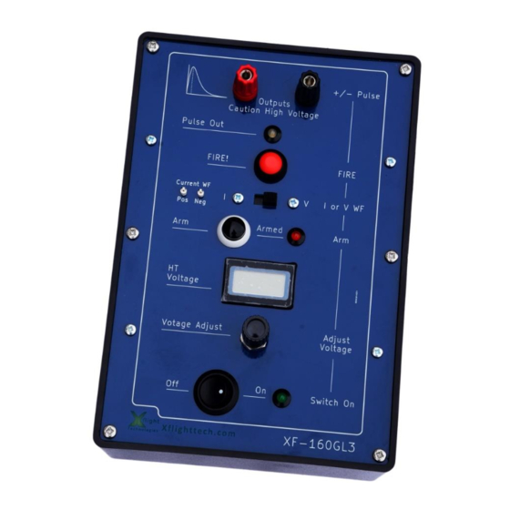
- Page 5 The XF-160GL3 main functions Pulse outputs – connect to UUT Outside screws (x6) to change batteries White LED lights up momentarily Press to send pulse as pulse is out onto the output output connectors Pulse current WF (internal magnetic Set for current...
- Page 6 Left for at least one minute before opening it Momentarily switching back on will confirm the voltage is at a safe level. The following precautions have been designed into the XF-160GL3 Lightning Pulse Generator to mitigate any danger to an operator.
- Page 7 (The output is 25mV per Amp with 400KHz bandwidth). Note on Calibration The XF-160GL3 itself does not need calibration. If it is required to use the unit as part of a formal qualification procedure this can be done by measuring the output pulse with a calibrated oscilloscope (under known and measured ambient conditions, e.g.
-
Page 8: Operation
300mA, (about 2.2 Watts of power), this would then give approximately 50 hours of continual use. It is important to ensure the XF-160GL3 is switched off prior to installing / changing the batteries. An internal, light activated, auto cut-out switch will remove power to the unit when the assembly printed circuit boards (PCBs) are removed. - Page 9 Negative Pulse output to the UUT ground b. Positive Pulse output to the UUT signal to be tested 10. Switch the XF-160GL3 on, ensuring the green LED illuminates 11. Repeat the procedure of Step1 above to output a pulse Negative Voltage Pulse Operation 12.
- Page 10 Positive Current Pulse Operation Follow the below procedure for injecting a positive current pulse: Step 1: Confirm Operation of the XF-160GL3 in stand-alone mode 1. Short circuit the Positive (+) pulse and the negative (-) output pulse terminals with a wire of at least 18 AWG thickness.
- Page 11 Negative Pulse output to the UUT ground d. Positive Pulse output to the UUT signal to be tested 12. Switch the XF-160GL3 on, ensuring the green LED illuminates 13. Repeat the procedure of Step1 above to output a pulse Negative Voltage Pulse Operation 14.
-
Page 12: Maintenance
If the unit is switched on, adjust the voltage to less than 50v. If the unit is off make sure it has been off for at least one minute. Unscrew the six screws closest to the edge of the XF-160GL3 box. Slowly lift the board assembly up and out of the box, making sure not to unnecessarily poke fingers in-between the boards or touch any of the board electronic components. - Page 13 Appendix A TVS Protection Application Notes 1. Testing generally tries to ensure any equipment can withstand two types of stress: a. A fast rise time to a high voltage followed by a more prolonged fall time from that voltage. This is a good test of Insulation strength. b.
- Page 14 If the signal is a high speed Ethernet signal then the capacitance would more than likely kill the signal. In this case very low capacitance gas discharge tube (GDT) technology can be considered. However there may then be issues of longevity associated with such a design.
- Page 15 Voltage WF 4 (O/C Volts) Current WF 1 (S/C Amps) 1600 Amplitude tolerances are +10%, -0% Note the XF-160GL3 does not support levels 4 and 5. The double exponential pulses are defined as: Temporal tolerances are +20%, -20% μ Above is known as a 6.4/69 s pulse.
- Page 16 maximum voltage this is easy to do, but regarding the current waveform it is necessary to calculate how much energy is to be dissipated. It is the energy dissipation in a component that causes the damage. For this discussion we are assuming a protection circuit of the form as shown below.
- Page 17 For the sake of this discussion let’s assume we can employ a resistor of say 100Ω, and still maintain all signal transition specifications. From equation 1 it is clear that the series resistance must be known before the energy can be calculated. With this in mind let’s find out the energy associated with a double exponential pulse.
- Page 18 �� ( �� ) is now the time varying voltage, in this case a straight line from the peak voltage at time = 0 to 0V at time = 2�� Running through the derivation gives the following equation for the energy: ��...
- Page 19 14.7V maximum breakdown voltage. This is the voltage at which the diode will definitely (if not before) be in breakdown. 19.9V maximum clamping voltage. This is the voltage across the diode at maximum current. Since we don’t really want any conduction (and so no power loss) at normal operating voltage of 12V and we don’t want any voltage greater than maximum 20V at the device to be protected, this diode would seem to be acceptable.
- Page 20 �� �� �� = �� ���������� ���� ���� �� �� 2�� = 19.9�� �� 30.2�� �� 2 �� 69μs = 0.0829J ���� Hence, in our example �� = 0.0829 ��. ���� Since 0.0394 J < 0.0829 J, this TVS would seem to be ok. Furthermore we can check on the Littelfuse data sheet by looking at the Peak Pulse Power rating chart.
- Page 21 �� ���� �� ���� �� �� In our example of 100Ω series resistor and the DO-160G required 5Ω output impedance (supported by the XF-160GL3), the level 3 power, as before is: �� (300 − 19.9) ���� �� = 747�� ����...
- Page 22 Any inductance at the pulse generator (the XF-160GL3 has, by design, a very low inductance output) could generate a small negative voltage at the UUT. Any inductance at the UUT itself (or cables to it) could potentially generate a very high voltage at the input.
- Page 23 at frequency) certain frequencies may be impeded. This can cause reflection of energy and so unwanted interference and noise. Copyright © 2020 Xflight Technologies LLC, Florida, USA...
- Page 24 Appendix B Pulse Derivations 1. Triangular Pulse Energy. From the basic formula for a straight line we can write: �� . �� ���� �� ( �� ) = − + �� … . ���������������� ��1 ���� �� Where: �� ( �� ) is the variable voltage (vertical axis) ��...
- Page 25 And by substituting equation B1 for �� ( �� ) , we can re-write equation B2 as follows: ��=�� �� −�� −�� ���� �� ∫ ( + 1) ( + 1) ���� �� �� �� �� �� ��=0 Where �� shows that the energy is for the exponential (x) pulse.
- Page 26 2. Half Sine Pulse Energy. We can write the time varying voltage as: ���� �� ( �� ) = �� ������ ( ) … . ���������������� ��5 ���� �� Where: �� ( �� ) is the variable voltage (vertical axis) ��...
- Page 27 ��=�� �� ���� ���� ∫ ������ ) ���� �� �� �� �� �� ��=0 It can then be shown that this evaluates to the following simple expression: �� �� ���� �� … . ���������������� ��6 �� �� �� �� �� ����...
- Page 28 ��=�� �� = ∫ �� ( �� ) ���� … . ���������������� ��2 ��=0 Since: ��(��) �� ( �� ) = �� �� Then: ��=�� �� ∫ �� ���� ���� ���� �� �� ��=0 Since in this case �� is just a constant this just evaluates to the following simple ����...
- Page 29 Appendix C XF-160GL3 Specifications Item Value Unit Unit length 220 (8.67) mm (inch) Unit width 150 (5.90 ) mm (inch) Unit height 64 (2.52) mm (inch) Unit weight 0.78 (1.85) Kg (lbs) Enclosure material ABS plastic / FR-4 TG130 Battery requirement (Batteries not provided) X6 1.2V (AA)
- Page 30 (the "Goods") in accordance with the terms and conditions of this Contract: Product Xflight XF-160GL3 Lightning Pulse Generator 6. INTELLECTUAL PROPERTY. Intellectual property created, made, or originated by the officers, employees, or contractors of Seller shall remain the sole and exclusive property of Seller.
- Page 31 10. INDEMNIFICATION. Buyer shall defend, indemnify, and hold harmless Seller, including its officers and agents, from any and all actual or alleged claims, demands, causes of action, liability, loss, damage and/or injury (to property or persons, including without limitation wrongful death), associated with the ownership and operation of the Goods of this contract.
- Page 32 parties shall continue to perform their respective obligations under this Contract. 13. NOTICE. Any notice or communication required or permitted under this Contract shall be sufficiently given if delivered in person or by certified mail, return receipt requested, to the addresses listed above or to such other address as one party may have furnished to the other in writing.
- Page 33 EXCHANGE OF GOODS The following provisions relate to the physical exchange of Goods and payment forming the transaction of this agreement. 19. TITLE/RISK OF LOSS. Title to and risk of loss of goods shall pass to the buyer upon delivery F.O.B. at the seller's place of home or business to an agent of the buyer including a common carrier, notwithstanding any prepayment or allowance of freight by the seller.
Need help?
Do you have a question about the XF-160GL3 and is the answer not in the manual?
Questions and answers