Table of Contents
Advertisement
Quick Links
Advertisement
Table of Contents

Summary of Contents for TeachLogic AR-960
- Page 1 AirLink owner’s manual Wireless Line Level Router...
- Page 2 AirLink AirLink AirLink owner’s manual...
- Page 3 notes Date of Purchase: Model Number: Serial Number: Notes:...
- Page 4 TeachLogic appreciates your confidence with your purchase of our AirLink system. Be assured that Hopefully this manual will provide all the informa- TeachLogic products are built to very high quality tion needed, however: our standards, incorporate state of the art technology, customer service depart-...
- Page 5 Read Instructions All safety and operation instructions should be read before operating this TeachLogic product. Retain Instructions Safety and operating instructions should be kept for future reference. Water & Moisture certifications This product should not be operated near water.
-
Page 6: Table Of Contents
AirLink owner’s manual transmitter table of contents Product Description............. Transmitter Panel Components....... Receiver Panel Components........Transmitter Setup Instructions......... Receiver Setup Instructions........Operating the AirLink Router System....7–9 Troubleshooting............Specifications............... Five Year Limited Warranty........ -
Page 7: Product Description
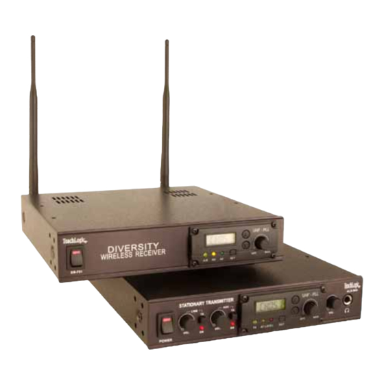
product description The AirLink system is a wireless audio router that transmits audio via an RF signal to a receiver. The system is comprised of a transmitter base station that transmits to a diversity receiver. The system operates in the UHF range (640–664 MHz). The system has 96 selectable preset channels. -
Page 8: Transmitter Panel Components
AirLink owner’s manual STATIONARY TRANSMITTER ALS-960 UHF-PLL LINE OFFM VOL. VOL. VOL. LEVEL POWER front of ALS-960 transmitter Power Switch and LED LCD Display: Channel # or Output Gain Control for Frequency Readout Balanced Input AF Transmission Indicator Transmit “on/off” for (Orange LED) Balanced Input Signal Peak Indicator (Red LED) -
Page 9: Receiver Panel Components
UHF-PLL UHF-PLL PRO. WIRELESS RECEIVER OFFM A/BR POWER front of DR-701 receiver Power Switch and LED Signal Peak Indicator (Red LED) RF Reception: Diversity A/B Channel Set: Lock/Unlock Antenna (Red/Green LED) Channel “Up/Down” Selector LCD Display: Channel # or Receiver Module: “on/off” Frequency Readout and Master Gain AF Signal Present Indicator... -
Page 10: Transmitter Setup Instructions
Do not attempt to change antenna orientation while in tightened condition. MICROPHONE MIXER note To extend the range of the AirLink AR-960 system, replace the antenna of the transmitter with a periodic- log antenna oriented in the horizontal position. DIGITAL MUSIC PLAYER RECORDER... -
Page 11: Receiver Setup Instructions
RECEIVER setup instructions Locate receiver at remote location • Plug power supply into AC power outlet • Connect audio output from receiver to input of • auxiliary sound system antenna installation Receiver DC IN 10~15V LOW/HI ANT. A ANT. B AF OUT Screw antenna into TNC connector loosely. -
Page 12: Operating The Airlink Router System
AirLink owner’s manual transmitter operating the AirLink router system Initially have all controls at minimum level • Turn on transmitter and receiver units • Turn on transmitter and receiver modules • LCD window will light and channel # display • Tx LED (Yellow) on transmitter will light •... -
Page 13: Troubleshooting
troubleshooting Problem Solution No Power Be sure unit is plugged in • Be sure you are using the • correct connector Check if power switch is • turned on Verify proper power • supply Verify AC power • Failed Receiver Signal Be sure that transmitter •... - Page 14 AirLink owner’s manual transmitter product description Channel Frequency Allocation 640–664 MHz LCD UHF TV Frequencies TV Channel 638–644 644–650 650–656 656–662 662–668 14 6...
-
Page 16: Specifications
AirLink owner’s manual transmitter specifications 96 Selectable Channels from 640–664 MHz Maximum Deviation 80 kHz, with Level Limiting Dynamic Range 110 dB Less Than 0.5% Pre/De-Emphasis 50 µs Frequency Response 70 Hz–17kHz RF Output 30 mW Spurious Emissions Less than 250 nW Inputs Balanced Line Level (Unbalanced Line Level (Stereo Phone Jack or Dual RCA) -
Page 17: Five Year Limited Warranty
TeachLogic RF products are guaranteed to be free of defects in workmanship or material for a period of three (3) years from date of original purchase, subject to the following conditions: 1. Warranty excludes defects caused by normal use and wear, any abuse, or failure to use the product in accordance per instructions. - Page 18 1688 Ord Way Oceanside, CA 92056 0018 • • • sales@teachlogic.com 1283 • • • www.teachlogic.com...
Need help?
Do you have a question about the AR-960 and is the answer not in the manual?
Questions and answers