Advertisement
Advertisement
Table of Contents

Summary of Contents for Broyhill 2721FM-32-201
-
Page 3: Safety Information
GENERAL BEST PRACTICES FOR ASSEMBLY: Read all instructions before starting Clear a large flat area to begin assembly Some steps may require a helper Hardware required is provided for each step Pay attention to orientation SAFETY INFORMATION Please read and understand this entire manual before attempting to assemble, operate or install the product. This equipment has been tested and found to comply with the limits for Class B digital devices, pursuant to Part 15 of the FCC rules. - Page 4 SAFETY INFORMATION (CONT’D) • This product is intended to fit most plasma and LCD televisions (up to 80 inches and weighing a maximum of 120 pounds). Using this item with loads heavier than the stated maximum can result in tipping and/or instability, which can result in injury or even death.
- Page 5 SAFETY INFORMATION (CONT’D) where it may fall into a bathtub or other water container. • To disconnect this appliance, turn controls to the OFF position, then remove plug from outlet. • ONLY connect to properly grounded outlets. • This appliance, when installed, must be electrically grounded in accordance with local codes, with the current CSA C22.1 Canadian Electrical Code or follow U.S.A.
-
Page 6: Parts List
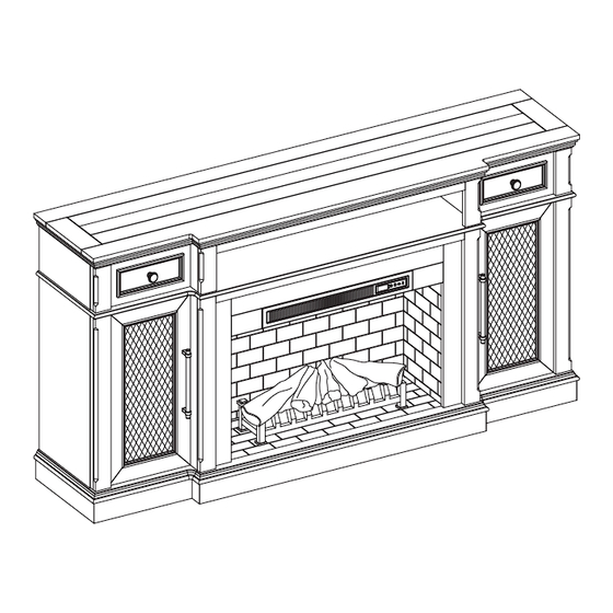
PARTS LIST Outer Wall Left Middle Wall Right Middle Wall Upper Opening Panel Shelf Back Panel Door Fireplace Brick Wall Fireplace Glass Front Base Fire Log Fireplace Grate Remote Control (Battery Inside) Heater... -
Page 7: Hardware List
HARDWARE LIST Ø1/4”*1-1/4” 19D*1mm Ø8*30mmL Bolt Washer Wooden Dowel Shelf Pin Ø6*14mmL Back panel mounting Hinge Hinge Screw Door Pull hardware with screw Ø6*12mmL Ø8*28mmL Ø5/32”*1-1/8” Allen Wrench Screw Long Screw Small Bolt Touch-up Pen PREPARATION Before beginning assembly of product, make sure all parts are present. Compare parts with package contents list and hardware contents list. - Page 8 STEP 1 Insert three wooden dowels (CC) into the holes of the base (K). Align the right middle wall (D) with the inserted wooden dowels and lower into place. Secure the right middle wall (D) to the base (K) with two washer (BB) and two bolts (AA) using the Allen Wrench provided (II) as shown in the diagram.
- Page 9 STEP 2 Insert three wooden dowels (CC) into the holes of the base (K). Align the left middle wall (C) with the inserted wooden dowels and lower into place. NOTE: Do not secure left middle wall (C) yet until the upper opening panel (E) is attached at step 4. Assembled View: Ø8*30mmL Wooden Dowel...
- Page 10 STEP 3 Insert two wooden dowel (CC) into each side of upper opening panel (E). Assembled View: Ø8*30mmL Wooden Dowel...
- Page 11 STEP 4 Carefully position the upper opening panel (E) into place between left middle wall (C) and right middle wall (D). Secure the left middle wall (C) to the base (K) with two washers (BB) and two bolts (AA) using the Allen Wrench provided (II) as shown in the diagram.
- Page 12 STEP 5 From behind the assembly, attach the fireplace glass front (J) by carefully lowering it into the front groove on the base (K). Secure the glass by turning the pre-assembled plastic knobs. Assembled View:...
- Page 13 STEP 6 Insert four wooden dowels (CC) into the outer holes of the base (K). Align the outer walls (B) with the inserted wooden dowels and lower into place. Secure the outer walls (B) to the base (K) with four washer (BB) and four bolts (AA) using the Allen Wrench provided (II) as shown in the diagram.
- Page 14 STEP 7 As shown in the diagram, insert the back panels (G) into the grooves of the middle walls (C, D) and outer walls (B) until fully inserted into the bottom grooves. Assembled View:...
- Page 15 STEP 8 Insert nine wooden dowels (CC) into the top outer holes on the outer walls (B) and middle wall (C, D). With assistance from another adult, align the holes in the top (A) with the inserted dowels and lower into place. Secure the top (A) to the middle and outer walls with ten washers (BB) and ten bolts (AA) using the Allen Wrench provided (II).
- Page 16 STEP 9 Secure the back panels (G) along the inside edges using the back panel mounting hardware (EE), by sliding the flat edge into the groove and tightening the screws with a Phillips screwdriver. “Phillips screwdriver not included” Assembled View: Back panel mounting hardware with screw “not included”...
- Page 17 STEP 10 With assistance from another adult, align the heater (P) with the corresponding holes and raise into place. Secure the heater (P) to insert braces with four long screws (KK) using Phillips screwdriver. “Phillips screwdriver not included” Assembled View: Ø8*28mmL Long Screw “not included”...
- Page 18 STEP 11 Position the fireplace grate (N) by inserting the bottom pins of the fireplace grate (N) into the holes on the base (K), secure by tightening two small bolts (LL) with a Phillips screwdriver. “Phillips screwdriver not included” Assembled View: Ø5/32”*1-1/8”...
- Page 19 STEP 12 Remove the film from the adhesive on the top of the fireplace grate (N) and place the fire log (M) on the center of the fireplace grate (N). Assembled View:...
- Page 20 STEP 13 Unfold the fireplace brick wall (I) and brackets. Assembled View:...
- Page 21 STEP 14 Insert the USB cable from behind through the cable hole on the fireplace brick wall (I). Attach the USB cable from the heater into the USB port behind the fireplace grate (N). Insert the fireplace brick wall (I) into the mantel, slotting it into the grooves on the base (K).
- Page 22 STEP 15 Insert shelf pins (DD) at desired height, ensuring they are level. Place the shelf (F) on top of the shelf pins (DD). Repeat for remaining shelf (F). Assembled View: Shelf Pin...
- Page 23 STEP 16 Place the hinges (FF) into predrilled hole on the door (H), securing with two hinge screws (GG). Repeat for the remaining hinges (FF). “Phillips screwdriver not included” Assembled View: Ø6*14mmL Hinge Hinge Screw “not included”...
- Page 24 STEP 17 Place the door pull (HH) into the predrilled hole on the door (H), securing with two door pull screws. Repeat for the remaining door pull (HH). “Phillips screwdriver not included” Assembled View: Door Pull “not included”...
- Page 25 STEP 18 Install the doors I. Loosen the screws on the hinge arms and plates pre-attached on the outer walls (B). II. Pick up door (H) and attach it to outer wall (B) by engaging both door hinges simultaneously. Please follow the steps below to combine the door hinges together.
- Page 26 STEP 19 If you need to adjust the doors, do so in the following manner. To adjust door up or down, loosen screws (a) on both hinges, adjust door, and retighten screws. To adjust door left or right, turn screws (b) on both hinges, in and out. To adjust door in or out, loosen screws (c) on both hinges, adjust door, and retighten screws.
- Page 27 STEP 20 NOTE: Use the pre-assembled levelers on the base of the fireplace to level the unit. Twist the levelers counter-clockwise to increase the height, twist clockwise to decrease the height. Assembly is now complete. With the help of another person, move the assembly to the final desired location. Once in final position you may plug the heater into the power outlet.
- Page 28 STEP 21 Remove drawer preassembled in top (A) by fully extending drawer. Locate black plastic levers on metal glide tracks at left and right sides of drawer box. To disengage drawer box from glides, simultaneously push down on right plastic lever and up on left plastic lever while gently pulling out drawer.
- Page 29 STEP 22 To reinstall drawer, slide glide roller (on track inside top) to front of top (A). Carefully align drawer box glide track (attached to sides of drawer box) with glide track (attached to inside of top). Making sure drawer is aligned and centered onto glides, gently push drawer.
- Page 30 MAXIMUM LOAD 6.8 kg / 15 lb MAXIMUM LOAD 6.8 kg / 15 lb MAXIMUM LOAD 6.8 kg / 15 lb SKU#810617768/ITEM#2721FM-32-201 DISTRIBUTION: Greentouch Home Limited ADDRESS: Room 4007, Central Plaza, 18 Harbour Road,Wanchai, Hong Kong COUNTRY OF ORIGIN: VIETNAM MANUFACTURE DATE: MAY, 2023 (This date is accordance with the actual manufacture date.)
- Page 31 OPERATING INSTRUCTIONS Control Panel Remote Control To use the remote control, first remove the plastic tab by gently pulling it out of remote control. Controls and Display The control panel will display the heater setting when the unit power is turned ON. Whichever control icon you press will display the current setting of the corresponding function.
-
Page 32: Memory Function
OPERATING INSTRUCTIONS (CONT’D) Heater Function (Control Panel Only) • Press the HEATER ICON to display the current heater setting. • Press the HEATER ICON again to scroll down through the heater settings. Note: Long-hold the icon to quickly scroll through settings. •... -
Page 33: Care And Maintenance
CARE AND MAINTENANCE • Make sure the unit is turned OFF, unplugged and the heating elements of heater are cool whenever you are cleaning the heater or fireplace. • Clean the metal trim using a water-dampened soft, clean cloth. DO NOT use brass polish or household cleaners as these products will damage the metal trim. -
Page 34: Troubleshooting
TROUBLESHOOTING PROBLEM POSSIBLE CAUSE CORRECTIVE ACTION Error E1 displayed The overheat sensor has Unplug unit, wait 15-20 minutes, then the sensor will reset on control panel. been engaged. itself. Plug the unit back in and turn on the heater. If the problem persists, call customer service. -
Page 35: One-Year Limited Warranty
ONE-YEAR LIMITED WARRANTY The manufacturer warrants that your new electric fireplace is free from manufacturing and material defects for a period of one year from date of purchase, subject to the following conditions and limitations. Install and operate this electric fireplace in accordance with the installation and operating instructions furnished with the product at all times. -
Page 36: Replacement Parts List
RC-HE85EL02 Heater-black KDI-01-23-M Shelf Pin B1044 Hinge PU17-1317FM-005 Door Pull PH-1856HW-08 MB DOOR PULL Touch-up Pen OF-0010 KD Hardware Pack 2721FM-32-201-HARDWARE PACK Glass Clips GLASS CLIPS Drawer Glide Set GLIDE 12X45-BLACK Leveler T-1007 Knob PH-JA3035 MB KNOB Printed in Vietnam...
Need help?
Do you have a question about the 2721FM-32-201 and is the answer not in the manual?
Questions and answers