Table of Contents
Advertisement
Quick Links
Advertisement
Table of Contents

Related Manuals for Vermes MHC 48-1

Summary of Contents for Vermes MHC 48-1
- Page 1 VTK-VS-BA-058e-B | User Manual MHC 48-1 | Introduction...
-
Page 2: Table Of Contents
Protective Equipment and Safety Clothing ............... 45 Attachments ................. 46 Dimensional Drawing MHC 48-1 ................46 Connection of MHC 48-1 with Adapter Cable MHC-48 for Power Supply, extendable ........................ 47 Connection Diagram PLC Interface ................53 Overview of the Function Keys of the MHC 48-1 ............54 Temperature Correction ................... -
Page 3: Introduction
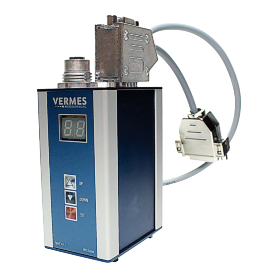
1.1) connected with a microdispensing system. The pictures in this manual might differ slightly from the final product. Picture 1: MHC 48-1 (with Adapter Cable MHC-48 for Power Supply, PLC & RS232) In the case of further questions, consult our Technical Support. -
Page 4: Intended Use
• Controlling the nozzle heater of your VERMES Microdispensing System • Keeping a dispensing application stable at a constant temperature The MHC 48-1 can control heaters working on an extra-low voltage basis (48 V). See the de- vices listed below. -
Page 5: Main Function: Heating
There are two main types of heater: nozzle heaters and cartridge heaters. With the MHC 48- 1, you can control nozzle heaters. For a list of heaters compatible with the MHC 48-1, check chapter 1.1. Picture 2 shows one example, the MDFH 48-CC, connected with a MicroDispensing Valve. -
Page 6: Quick Start
Picture 4: Adapter Cable MHC-48 for Power Supply, PLC & RS232 Picture 5: Adapter Cable MHC-48 for Power Supply, extendable Plug the adapter cable in the sub-D socket on top of your MHC 48-1 (see Picture 6). Screw the sub-D depth bolts tight. - Page 7 Connect the 4-pin PCB connector of the adapter cable with the counter part of your power supply (see Picture 7 and Picture 8). You power supply must be set to 48 V DC. Picture 7: Power connection (not yet connected) Picture 8: Power connection (connected) VTK-VS-BA-058e-B | User Manual MHC 48-1 | Quick Start...
- Page 8 After the start the display will show “OF” (= off), since the heater is OFF. Later you can change the settings of your MHC 48-1, so that the heater is ON after the start-up of the MHC 48-1 and the display shows the current temperature (see chapter 4.7).
- Page 9 “OF”. CAUTION! (High temperatures) The MHC 48-1 can control integrated nozzle heaters at temperatures of up to 99 °C. Do not touch the nozzle area during operation. Afterwards only touch it once it has cooled down. Step 7: Save target temperature If you change a target temperature in the main menu, this is not saved after a re-start.
-
Page 10: Heater Control Unit Mhc 48-1
MHC 48-1. It also explains how to set it up. IMPORTANT NOTE! (No ON/OFF button) The MHC 48-1 has no separate ON/OFF button. Just connecting the power supply (48 V DC) will turn it ON and disconnecting it will turn it OFF. -
Page 11: Front Side
You can lock the keypad with the serial command “SYS:KLOCK1”. You can unlock the keypad with the serial command “SYS:KLOCK0” or by switching OFF the MHC 48-1 and then back VTK-VS-BA-058e-B | User Manual MHC 48-1 | Heater Control Unit MHC 48-1... -
Page 12: Top Side
Connects the control unit to a power supply. It needs 48 V DC. Base power consumption of the MHC 48-1 is 5 W. For heaters, check chapter 1.1. VTK-VS-BA-058e-B | User Manual MHC 48-1 | Heater Control Unit MHC 48-1... -
Page 13: Function Keys
With the serial command “SYS:KLOCK1” from your computer you can lock the keypad of the MHC 48-1. If the lock is ON, pressing a key only results in the message “lo” (=”locked”) on the display. To deactivate the key lock, you have to send the command “SYS:KLOCK0” or to re-start the MHC 48-1. - Page 14 Set key longer. Afterwards the display jumps back to the menu item from where you came. In case of an error, you can confirm the error message by shortly pressing the Set key. VTK-VS-BA-058e-B | User Manual MHC 48-1 | Heater Control Unit MHC 48-1...
-
Page 15: Beeper Alarm
Beeper alarm The MHC 48-1 has an acoustic warning system. The acoustic warning system is the beeper alarm. The alarm beep sounds in four situations: • After start-up to announce the system is ready (longer beep) • When an error appears (continuous series of short beeps until you have confirmed... -
Page 16: Setting Up The Mhc 48-1
You can mount the MHC 48-1 with the clamp for a top head rail at the bottom (see Picture 16) or with the hook-and-loop fastener at the side. Additionally there are two bore holes in the back side for another top hat rail (see Picture 17). - Page 17 Push the Adapter Cable MHC-48 for Power Supply, PLC & RS232 into the sub-D socket on top of the MHC 48-1 (see Picture 18). Screw it tight with the two UNC 4-40 screws. This adapter cable enables the power supply for the MHC 48-1 and offers a PLC socket and a serial RS-232C socket.
- Page 18 Picture 22: MDFH 48-CC CAUTION! (High temperatures) The MHC 48-1 can control integrated nozzle heaters at temperatures of up to 99 °C. Do not touch the nozzle area during operation. Afterwards only touch it once it has cooled down. VTK-VS-BA-058e-B | User Manual MHC 48-1 | Heater Control Unit MHC 48-1...
- Page 19 Power connection of the MHC 48-1 The MHC 48-1 needs an external power supply of 48 V DC. You have to connect this to the 4-pin PCB connector (see Picture 24). The connection has to go to pin 2 and pin 3.
-
Page 20: Menu Structure
Menu Structure The menu of the heater control unit MHC 48-1 contains two menu levels. The top level is the basic level. The basic level offers you temperature information and the basic settings of your heater (ON/OFF, target temperature). In the second menu level, you have the menu items where you can change parameters or settings (e.g. - Page 21 “--“. When the connected heater is not activated, the display shows “OF” (for “OFF”). This is the first page when you start the MHC 48-1. The menu also jumps back to this page when returning from the second menu level.
-
Page 22: Second Menu Level
If you press the Set-key longer in a submenu, you cancel your changes and the display jumps again back to the according menu item. This is an overview of the second menu level of the MHC 48-1: Picture 26: Second menu level IMPORTANT NOTE! (Priorities of settings) The setting of the heater during start-up (menu item H.2) can be in contradiction with the... - Page 23 1 – “Soft reset”, just a re-start of the system 2 – Reset with return of the MHC 48-1 to the factory settings 3 – Reset where the boot loader is started (necessary when there is a new firmware revision)
-
Page 24: Communication Interfaces
COMMUNICATION INTERFACES The MHC 48-1 has a 9-pin serial interface, RS-232C, and a 15-pin PLC interface as its commu- nication interfaces. Serial Interface RS-232C: 9-Pin Sub-D Picture 27: Schematic RS-232C interface The local interface is structured according to SCPI Standard. The serial interface operates with a software handshake. -
Page 25: Commands
YES and “0” stands for NO. INFORMATION! (Response to commands) The MHC 48-1 gives a response to every command send to it (exception: “SYS:RST”). Possible responses are: A value or set of values, asked for in the command (prefaced •... -
Page 26: Command Overview
16. SYS:CON:EXT<ON/OFF>,<Pin HIGH/LOW>,<save Y/N> 17. SYS:CON:EXT? 18. SYS:CON:PI 19. SYS:CON:PI? 20. SYS:RST<reset type> 21. SYS:KLOCK<key lock ON/OFF> 22. SYS:KLOCK? 23. SYS:ERR:QUIT 24. SYS:FWV? 25. SYS:LOG:SHOW 26. SYS:LOG:CLEAR 27. *IDN? 28. HELP VTK-VS-BA-058e-B | User Manual MHC 48-1 | Communication Interfaces... -
Page 27: Command Explanations
“1” would be “YES” and “0” would be “NO”. This parameter is optional. If you omit it, the mean value will not be reset. VTK-VS-BA-058e-B | User Manual MHC 48-1 | Communication Interfaces... - Page 28 8.3. We recommend its use only after you have fully understood the system. Example: Input: CON:TCORR2000,20000,0 Result: The best-fit parameters of the temperature correction are changed. These settings are not saved. Return: VTK-VS-BA-058e-B | User Manual MHC 48-1 | Communication Interfaces...
- Page 29 “NO”. This parameter is optional. If you omit it, the setting will not be saved. Note: After you have send this command, you have to adjust the baud rate at your PC as well and to re-start the serial connection. Example: Input: SYS:COM:SER:BAUD10,1 VTK-VS-BA-058e-B | User Manual MHC 48-1 | Communication Interfaces...
- Page 30 0, 1 SYS:CON:EXT<ON/OFF>,<Pin HIGH/LOW>,<save YES/NO> Description: This command activates/deactivates the function, to turn the MHC 48-1 ON/OFF via the PLC interface (“1” function is activated, “0” is function is de- activated). With the parameter “Pin HIGH/LOW” you determine, which pin setting acti- vates the heater.
- Page 31 SYS:CON:EXT? Description: With this command, you can check if the function, to turn the MHC 48-1 ON/OFF via the PLC interface, is activated (ON) or deactivated (OFF). You receive also note, if the heater is activated with the pin on “HIGH” or on “LOW”.
- Page 32 The error list is shown. Return: 1. Err. 2 2. Err. 66 3. Err. 66 SYS:LOG:CLEAR Description: This command deletes the list of errors. Example: Input: SYS:LOG:CLEAR Result: The error list is deleted. VTK-VS-BA-058e-B | User Manual MHC 48-1 | Communication Interfaces...
- Page 33 This command shows the system name and the serial number of the MHC 48-1. Example: Input: HELP Result: The name of the system and the current revision of firmware and boot loader are shown. Return: MHC 48-1 (SN:MHC0329) VTK-VS-BA-058e-B | User Manual MHC 48-1 | Communication Interfaces...
-
Page 34: Plc Interface: 15-Pin, Sub-D
___________ Output 0/+24 V, Error signal =4.4 kΩ (high), =2.2 kΩ (low) ___________ ___________ ___________ You can find a connection diagram for the PLC interface in the attachments (see paragraph 8.3). VTK-VS-BA-058e-B | User Manual MHC 48-1 | Communication Interfaces... -
Page 35: Error Messages
(“XX” representing the error code). You can proceed with your application, once you have acknowledged the error, unless it is error code “0”. Then you have to re-start the MHC 48-1. Should an error appear repeatedly or if you cannot solve it at all, then contact our Technical Sup- port (see page 3). - Page 36 MHC 48-1 too hot Er. 70 Internal error in the clock pulse supply of the processor Er. 71 Internal error with the EEPROM of the MHC 48-1 Er. 74 Heater error (suspicious temperature increase) Er. 75 Heater error (target temperature cannot be reached) Er.
-
Page 37: Explanations Of Error Messages
Affected: Error of the RS-232C interface • Check RS-232C settings (baud rate, parity bit, number of data/stop Error handling: bits). MHC 48-1 and the connected computer must have the same settings. Er. 2 Timeout While Transmitting via RS-232C Description: RS-232C timeout. - Page 38 Er. 52 Error while Initializing the Internal Memory of the Heater Description: An error occurs while initializing the internal memory of the heater. With this error, the heater is turned OFF automatically. VTK-VS-BA-058e-B | User Manual MHC 48-1 | Error Messages...
- Page 39 • Acknowledge error by pressing the Set key or by sending the serial Error handling: command “SYS:ERR:QUIT”. • Turn heater ON again. • In case the error occurs repeatedly, contact our Technical Support (see page 3). VTK-VS-BA-058e-B | User Manual MHC 48-1 | Error Messages...
- Page 40 Er. 61 Connected Device Incompatible Description: The device connected with the MHC 48-1 is incompatible. It is either an incorrect type of heater or a different kind of device. With this error, the heater or device is turned OFF automatically.
- Page 41 Error with the Power Supply Description: A problem occurs with the power supply. The voltage has not the cor- rect 48 V or the power fluctuates (voltage deviation bigger than +/-1 V). VTK-VS-BA-058e-B | User Manual MHC 48-1 | Error Messages...
- Page 42 • Acknowledge error by pressing the Set key or by sending the serial Error handling: command “SYS:ERR:QUIT”. • Switch OFF MHC 48-1, so that it can cool off, if necessary. • In case the error occurs repeatedly, contact our Technical Support (see page 3).
- Page 43 Er. 71 Error with the Internal EEPROM of the MHC 48-1 Description: An error occurs while writing on the internal EEPROM of the MHC 48-1. With this error, the heater is turned OFF automatically. Affected: Internal error • Acknowledge error by pressing the Set key or by sending the serial Error handling: command “SYS:ERR:QUIT”.
-
Page 44: Safety Notes
• DIN EN 982 Safety Requirements for Fluid Power Systems and their Components – Hydrau- lics. Despite this comprehensive inherent safety structure, the operation of the MHC 48-1 may entail danger • For the health of the operator or a third party, •... -
Page 45: Specification And Technical Notes
• An overall and gloves resistant to the corresponding chemical fluid When you work in the direct vicinity of an MDS for a prolonged period, you should also wear ear protection. VTK-VS-BA-058e-B | User Manual MHC 48-1 | Safety Notes... -
Page 46: Attachments
ATTACHMENTS Dimensional Drawing MHC 48-1 VTK-VS-BA-058e-B | User Manual MHC 48-1 | Attachments... -
Page 47: Connection Of Mhc 48-1 With Adapter Cable Mhc-48 For Power Supply, Extendable
2.5 cm between them. Do not obstruct natural convection. Ventilation from the bottom side and air exhaust above are important. You can mount the MHC 48-1 with the clamp for a top head rail at the bottom (see Picture 31) or with the hook-and-loop fastener at the side. - Page 48 MHC 48-1 (see Picture 32). Screw it tight with the two UNC 4-40 screws. This adapter cable enables the power supply for the MHC 48-1 and offers the possibility to connect a PLC socket and a serial RS-232C socket. Screw the sub-D depth bolts tight.
- Page 49 You have to connect the heater cable of your heater (e.g. MDFH 48-CC, see Picture 35 with MDFH isolation body NAN-fix included) with the socket for heater on top of the MHC 48-1 (see Picture 36). Push the plug in; then screw the connection tight. You should press the case slightly forward while screwing.
- Page 50 Picture 38: MDFH 48-CC CAUTION! (High temperatures) The MHC 48-1 can control integrated nozzle heaters at temperatures of up to 99 °C. Do not touch the nozzle area during operation. Afterwards only touch it once it has cooled down. Extending the adapter cable for PLC or RS-232C interface You can equip the adapter cable MHC-48 for power supply, extendable with a PLC interface and with a RS-232C interface.
- Page 51 Pin 5 (ground) • The spring-loaded terminals will hold the cables. You find more information about the serial interface of the MHC 48-1 in chapter 5.1 and about the serial commands in chapter 5.2. VTK-VS-BA-058e-B | User Manual MHC 48-1 | Attachments...
- Page 52 To retrieve the Temp. OK signal • To retrieve an error signal In case you do not need all three functions, you only have to connect the pins necessary for the desired function(s). VTK-VS-BA-058e-B | User Manual MHC 48-1 | Attachments...
-
Page 53: Connection Diagram Plc Interface
Connection Diagram PLC Interface VTK-VS-BA-058e-B | User Manual MHC 48-1 | Attachments... -
Page 54: Overview Of The Function Keys Of The Mhc 48-1
Overview of the Function Keys of the MHC 48-1 The following table shows you the functions of the function keys (see chapter 4.4) in the dif- ferent menu levels (see chapter 4.7). Menu Keys Down Up + Down Current Short: Switch to... - Page 55 “C.3” selection selection ture” (without sav- ing) Short: Switch to Short: Switch to Short: Switch to Short: Switch to Submenu Changing “0.0” “C.3” “Current tempera- (2. Menu level) Value “A.L” ture” VTK-VS-BA-058e-B | User Manual MHC 48-1 | Attachments...
- Page 56 (=soft reset) Long: Change Long: Moves Long: Moves Long: Switch to aborted and switch quickly up in the quickly down in the “Current tempera- to “0.0” selection selection ture” (without sav- ing) VTK-VS-BA-058e-B | User Manual MHC 48-1 | Attachments...
-
Page 57: Temperature Correction
For values of m between 200 and 1000, the resulting line is less steep than the default line. Picture 42: Default setting of the temperature correction VTK-VS-BA-058e-B | User Manual MHC 48-1 | Attachments... - Page 58 (blue line). In this example, the corrected tempera- ture is above the temperature without correction. This case will be the exception. Picture 44: m higher (T = 20000, m = 1500) VTK-VS-BA-058e-B | User Manual MHC 48-1 | Attachments...
-
Page 59: Finding The Correction Parameters M And T
Finding the Correction Parameters m and T To find the correction parameters for your application, you have to measure the tempera- ture at the nozzle independently from the MHC 48-1. Note the target temperature t the temperature t you have measured. Select another target temperature t... -
Page 60: Entering The Correction Parameters M And T
You need your own equipment to measure the temperature at the nozzle inde- pendently. You have to find two sets of values, which you then use to calculate the correc- tion parameters for your application. VTK-VS-BA-058e-B | User Manual MHC 48-1 | Attachments... -
Page 61: Firmware Update With The Mhc_ Firmware_Loader
You receive the new firmware from VERMES Microdispensing as a HEX file. You have to copy this HEX file into the subdirectory “Data” of the MHC_Firmware_Loader. Connect your computer with the serial interface RS-232C of the MHC 48-1. Be aware that a firmware update will delete all entries in the error log. - Page 62 Step 3 The next prompt is “Insert Baudrate”. As baud rate, enter the value set at the MHC 48-1 (standard value 115200, see Picture 48) and confirm with “Enter”. Picture 48: Enter baud rate Step 4 The program now switches the MHC 48-1 into the bootloader mode. This is shown by the following message (see Picture 49).
- Page 63 Device? <y/n>” (see Picture 51). Press “y” for “Yes” and confirm with “Enter”. Picture 51: Confirm firmware update The old firmware is deleted and replaced by the new revision (see Picture 52). Picture 52: Firmware is updated VTK-VS-BA-058e-B | User Manual MHC 48-1 | Attachments...
- Page 64 Afterwards the MHC 48-1 is getting re-started. This process lasts for approx. 15 s. You have completed the firmware update successfully. You can continue to work with the MHC 48-1. In case you have accidently chosen the wrong COM port (Step 2) or entered the wrong baud rate (Step 3), an error message appears (see Picture 53).
-
Page 65: Ec Declaration Of Conformity
EC Declaration of Conformity VTK-VS-BA-058e-B | User Manual MHC 48-1 | Attachments... -
Page 66: Index
C.1 23 H.3 (menu) 23 C.2 23 heater 4, 5 C.3 23 compatible heaters 4 Current Temperature 21 connecting the heater 8, 17, 48 H.1 23 dangers 9, 18, 49 H.2 23 VTK-VS-BA-058e-B | User Manual MHC 48-1 | Index... - Page 67 16 Up key 13 Top Side 12 Up key and Down key together 14 Weight 10 ventilation 16, 46 MHC 48-1 3, 5, 10, 20 Weight 10 MHC_Firmware_Loader 60 VTK-VS-BA-058e-B | User Manual MHC 48-1 | Index...
Need help?
Do you have a question about the MHC 48-1 and is the answer not in the manual?
Questions and answers