Advertisement
Available languages
Available languages
Quick Links
QwikSwap® X3 Installation Instructions
To replace Constant Torque ECM Blower Motors with a Permanent Split Capacitor
(PSC) Motor and Variable Speed Control Board
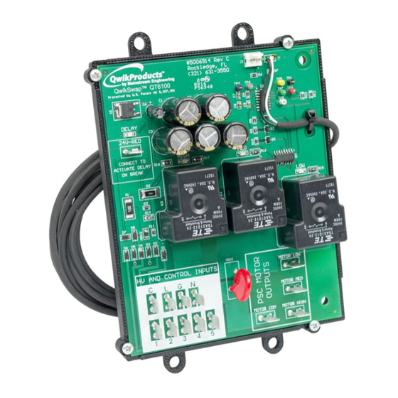
C AUTI O N
To prevent death, injury, or property damage, read and follow all instructions and warnings, including labels shipped with or
attached to unit.
WA RNI NG
Improper installation, adjustment, alteration, service maintenance, or use can cause explosion, fire, electrical shock, or other
conditions that could cause personal injury or property damage. For use by qualified technicians only.
1
Turn off power.
Verify that you have a Constant Torque Blower
2
motor such as an X13® or SelecTech® Constant
Torque ECM motor.
3
Note the terminal location and corresponding
color of each wire that connects to the blower
motor. A reference diagram is shown below for
convenience. Disconnect these wires from the motor
(if they are part of a
molded plug, simply
C
L
G N
unplug it).
1
2
3
4
4
Remove the old blower motor and note the shaft
size, frame size (typically 48Y) operating voltage,
direction of rotation and motor horsepower.
SHAFT SIZE / ROTATION:
CW
FRAME SIZE:
VOLTAGE:
HORSEPOWER:
5
Install a new Permanent
Split Capacitor (PSC)
Blower motor with the
specifications noted in
Step 4. Properly ground
the motor and install the
capacitor in a location that
protects the terminals from a
short circuit or ground fault.
Identify a good mounting location
6
sufficient clearance or use the supplied
self-drilling sheet metal screws to attach
the mounting bracket.
Unit may be mounted flat without
the mounting bracket using the four
HUMIDITY
SENSOR
mounting tabs/holes on the PCB backer
J2
1
board and four sheet metal screws.
USE QT6001
C6
+
R2
Install the power and control wires that
U1
7
were removed from the old motor onto
R1
R3
the matching terminals of the QwikSwap X3 board.
Refer to the wiring diagram created in Step 3 for proper
D6 D5 D4 D3 D3
D1
connection locations.
!
The terminals on the wires
HV AND CONTROL INPUTS
that were removed from the
C
old motor
MUST BE FULLY
INSULATED
or part of a molded
plug that will plug directly into
the QwikSwap X3 board.
1
8
Connect the PSC blower motor power leads
5
(HIGH, MED, LOW, COM) to the corresponding
output terminals (HIGH, MED, LOW, COM) on the
QwikSwap board.
!
If the PSC motor
leads do not
#5006914 Rev c
MADE IN USA
Rockledge, FL
J1
(321) 631-3550
J2
QwikSwap®
QT6100
R7
R6
have insulated
Protected
by
U.S.
Patent
No 9, 2007,
001
TP4
TP6
TP5
TP1
U2
TP2
TP7
TP3
TP8
terminals, four
DELAY
Q1
CCW
24V-RED
Q2
insulated 1/4
Q3
CONNECT TO
HIGH
MED
ACTIVATE DELAY
R18
R17
R16
ON BREAK
inch female
R2
LOW
R1
R3
quick disconnect
R14
D8
D7
terminals have
D6
D5
D4
D3
D2
D1
F1
SLOW BLOW
20A, 250VAC
been provided to
MOV1
HV AND CONTROL IMPUTS
MOTOR LOW
connect the PSC
MOTOR MED
power leads to the
MOTOR COM
MOTOR HIGH
QwikSwap Board.
!
If the new PSC blower motor has quick disconnect terminals instead of
wires, you will have to fabricate the four wires (Minimum 14 gauge) with
quick disconnect terminals at each end to connect the High, Medium, Low
and Common connections from the QwikSwap to the PSC motor. Eight
insulated 1/4 inch female quick disconnect terminals have been provided.
If the new blower motor has more than three speeds, use the highest,
lowest and one of the mid-range speeds.
If the new blower motor only has two speed taps, jumper the low- and
medium-speed quick disconnect connectors on the QwikSwap board
together and connect them to the low speed tap on the motor.
WARNING: Do not jumper the motor windings.
Mount the QwikSwap
9
board to its mounting bracket
or mount flat using PCB backer
board tabs/holes
!
Secure the QwikSwap to the bracket using the
supplied plastic clips.
Press the clips through the bracket holes until
the clips snap in place.
Attach the thermistor to an evaporator return
10
bend near the coil inlet.
!
Route the thermistor wire to the evaporator, and
using the supplied loop clamp,
attach the thermistor to
any return bend near the coil inlet.
Secure the clamp using the supplied
with
plastic ratchet rivet.
For furnace systems, route the
thermistor wire outside of the
ignition chamber by drilling a 5/16" hole
and using the supplied grommets.
QwikSwap™ QT6100
To activate a 3-minute delay after
MADE IN THE USA / PATENTS PENDING
Thermistor
J1
11
J5
J3
J4
break
(which will keep the blower
C2
C3
operating for 3 minutes after the
C4
R10 R9 R8
C1
C8
Q3 Q2 Q1
C9
C5
thermostat stopped the call for
heating or
cooling), connect the R
terminal of the QwikSwap X3
board to the red thermostat
wire
(24-volt hot leg side of the
transformer).
F1
20A, 250VAC
!
#5006914 Rev c
MADE IN USA
SLOW BLOW
Rockledge, FL
J1
(321) 631-3550
J2
If the R terminal on the QwikSwap X3 board is left unconnected the X3 will
QwikSwap®
QT6100
R7
R6
MOV1
001
TP4
TP6
TP5
TP1
Protected
by
U.S.
Patent
No 9, 2007,
LOW
U2
TP2
TP7
TP3
still function properly, however there will be no delay after break.
TP8
DELAY
L
G
N
Q1
24V-RED
Q2
MED
Q3
CONNECT TO
HIGH
MED
ACTIVATE DELAY
R18
R17
R16
ON BREAK
R2
LOW
R1
R15
R3
COM
HIGH
R14
D8
D7
2
3
4
5
D6
D5
D4
D3
D2
D1
F1
SLOW BLOW
20A, 250VAC
MOV1
HV AND CONTROL IMPUTS
MOTOR LOW
MOTOR MED
MOTOR COM
MOTOR HIGH
R15
12
13
14
!
B
A
#5006914 Rev c
MADE IN USA
Rockledge, FL
J1
(321) 631-3550
QT6100
QwikSwap™
R6
Protected
by
U.S.
Patent
No 9, 2007,
001
TP4
TP6
U2
TP2
DELAY
Q1
24V-RED
Q2
Q3
CONNECT TO
HIGH
MED
ACTIVATE DELAY
R18
R17
R16
ON BREAK
R2
200 Yellow Place, Rockledge, FL 32955 / 321-631-3550
R1
R3
All marks shown within this document are properties of their respective owners, X13® is a registered
R14
Trademark of Regal Beloit®. SelecTech®, Emerson®, U.S. Motors® and Nidec® are registered trademarks
D8
of Nidec Motor Corporation. QwikProducts® and QwikSwap® are registered trademarks of
D7
Mainstream Engineering Corporation®, Rockledge, Florida 32955, (321) 631-3550
D6
D5
D4
D3
D2
© 2022 Mainstream Engineering Corporation . All rights reserved.
D1
F1
U.S. Patents #9,207,001, #9,417,005 and Other Patents Pending
SLOW BLOW
20A, 250VAC
MOV1
HV AND CONTROL IMPUTS
Typical System Wiring
MOTOR LOW
These wires previously
MOTOR MED
plugged into X-13® motor
QwikSwap® X3 Board
N
MOTOR COM
MOTOR HIGH
L2/N
High
110-240 VAC
Voltage
L
L1
Wires
G
GND
GRN
C
BLU
Low Voltage
1
24 VAC
2
Thermostat
3
Wires
GRN
4
R (Optional)
Thermostat
5
To Heater Contactor Coil
RED
#5006914 Rev c
MADE IN USA
Rockledge, FL
J1
(321) 631-3550
QwikSwap®
QT6100
R6
Protected
by
U.S.
Patent
No 9, 2007,
001
TP4
TP6
U2
TP2
DELAY
Q1
24V-RED
Q2
Q3
CONNECT TO
HIGH
MED
ACTIVATE DELAY
R18
R17
R16
ON BREAK
R2
R1
R3
R14
D8
D7
D6
D5
D4
D3
D2
D1
F1
SLOW BLOW
20A, 250VAC
MOV1
HV AND CONTROL IMPUTS
MOTOR LOW
MOTOR MED
MOTOR COM
MOTOR HIGH
When using the optional QT6001
humidity sensor, connect the
sensor following the QT6001
installation instructions.
Using the supplied tie wraps, bundle any excess wires
to avoid interference with the blower.
Reconnect power.
Need Help?...
View an online video installation
X
tutorial at www.qwik.com/qwik-swap/
Scan this code with your smartphone
X
to visit our QwikSwap Guide
X
Chat online
with "Live Help"
J2
at our website.
R7
TP5
TP1
TP7
TP3
TP8
www.qwik.com/qwik-swap/
LOW
R15
U.S.A. INNOVATION
COM
COM
SPEED
HIGH
PSC
MED
Blower
Capacitor
Motor
LOW
GND
J2
R7
TP5
TP1
TP7
TP3
TP8
WIRING
DIAGRAM
LOW
R15
1201820001
5008218_REV-D
2232022
Advertisement

Summary of Contents for Mainstream Engineering QwikSwap X3
- Page 1 SLOW BLOW Rockledge, FL of Nidec Motor Corporation. QwikProducts® and QwikSwap® are registered trademarks of (321) 631-3550 If the R terminal on the QwikSwap X3 board is left unconnected the X3 will QwikSwap® QT6100 Note the terminal location and corresponding MOV1 Mainstream Engineering Corporation®, Rockledge, Florida 32955, (321) 631-3550...
- Page 2 Nidec Motor Corporation. QwikProducts® y QwikSwap® son marcas comerciales Si la terminal R del tablero QwikSwap X3 se deja sin conectar, el X3 seguirà funcionando 20A, 250VAC Observe la ubicación de la terminal y el color...
Need help?
Do you have a question about the QwikSwap X3 and is the answer not in the manual?
Questions and answers