Advertisement
Quick Links
Advertisement

Related Manuals for Sub-Zero SZ-CR2


Summary of Contents for Sub-Zero SZ-CR2
- Page 1 SZ-CR2 DUAL SET POINT COLD ROOM CONTROLLER Instruction Manual...
- Page 2 Activate/Deactivate Door Open Digital Input. Fault Sensing Delay for Door Open Digital Input. Output status on Door Open Fault. Delay time for Temperature updating Door Open Digital Input Fault. Time duration to start Compressor with High Set Point. 16-17 SZ-CR2...
- Page 3 Enable/Disable Light Relay ON at Door Open. Clear Compressor1 Run Hours. Clear Compressor2 Run Hours. Clear Fault Log Display during Defrost. Default (Normal) Display. Display Delay. Activate Alarm Relay. Ht or Lt Alarm Power ON Delay. Time Delay to activate Alarm Relay at Door Open. SZ-CR2...
- Page 4 Balanced defrost frequency for Compressor 1. 29-30 Balanced defrost frequency for Compressor 2. View last 10 Fault Log. End of Programming. LED Indications 31-32 Fault Messages 32-33 Operating Messages Password Function High and Low Temperature Logging Function Wiring Diagram Caution for you Safety SZ-CR2...
- Page 5 • The operation is very user friendly and is easily understood with the examples in the instructions below. • Various parameters help set up the instrument functions for different applications. • The SZ-CR2 can be used for applications with a measuring range from -45.0⁰C to 70.0⁰C. • Defrost Application •...
- Page 6 LP (Low Pressure Input), SPPR Input 230V operated for Compressor 2 HP (High Pressure Input), LP (Low Pressure Input), SPPR Input Door Open Fault (Potential Free) Resolution : +/- 1°C / 0.1°C / 1°F (Selectable) Accuracy : +/- 1°C / 1°F SZ-CR2...
-
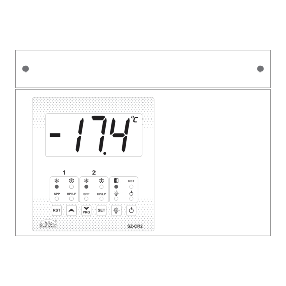
Page 7: User Interface
Note: If controller is in Set Mode/Program Mode/Run Hour and Fault Log Mode, in case of inactivity of keys, it will return to parameter view mode in 30 seconds and will return to Main screen in next 30 seconds. SZ-CR2... -
Page 8: Set Mode
Min. Max. Fac. Compressor will be OFF when Control (Main) (LS+1)°C (HS-1)°C 0°C Temperature reaches or goes below 0.0°C. CF = F Note: Min. Max. Fac. This parameter is considered only if, CS not equal to (LS+1)°F (HS-1)°F 32°F SZ-CR2... - Page 9 This parameter is considered only if CS is not equal to (LS+1)°F (HS-1)°F 32°F Function: To end Programming in Set Mode. Once the key is pressed, the Controller goes into the To end programming Normal Mode and displays the Temperature and all press "SET" key. settings are recorded. SZ-CR2...
-
Page 10: Program Mode
50.0°C 1.0⁰C is considered for clearing the fault. rS = 1 Where, P3 = Low Temperature Alarm Set Point. In °C Min. Max. Fac. (P3+1)°C 50°C 50°C (Message on Display) CF - F Min. Max. Fac. (P3+1)°F 122°F 122°F SZ-CR2... - Page 11 Example: Setting this parameter at 50.0°C will not allow Min. Max. Fac. the Set Point to go above 49.0°C (HS-1.0). (SP+1.0)°C 50.0°C 50.0°C rS = 1 In °C Min. Max. Fac. (SP+1)°C 50°C 50°C CF = F Min. Max. Fac. (SP+1)°F 122°F 122°F SZ-CR2...
- Page 12 2.0°C, the Min. Max. Fac. relay will cutin (restart) at 2.0°C (0.0°C + 2.0°C). 1.0°C 20.0°C 2.0°C rS = 1 In °C Min. Max. Fac. 1°C 20°C 2°C CF = F Min. Max. Fac. 1°F 20°F 2°F SZ-CR2...
- Page 13 Compressor. This delay starts once the Compressor Relay Min. Max. Fac. is ON. 0 Min 20 Min 0 Min Example: If this parameter is set at 2 minutes, then the Compressor Relay will remain ON for minimum 2 minutes, though Set Point is achieved. SZ-CR2...
- Page 14 Min. Max. Fac. When set to, = Defrost of one Compressor at a time. (1) = Simultaneous defrost both Compressors. Note: • This parameter is considered only if CS = btH and P71, P72 not equal to 0. SZ-CR2...
- Page 15 This is the amount of time between two Defrost Cycles. Example: As explained for P71 Parameter. Min. Max. Fac. Note: 1 Hr 31 Hrs 6 Hrs • This parameter is not considered if CS = C2 and P71 = 0. SZ-CR2...
- Page 16 Defrost takes place. And Defrost take place once the conditions become suitable for Defrost. Note: • This parameter is not considered if CS = C1. and P72 = 0. SZ-CR2...
- Page 17 For Door Open Digital Input, if this parameter is set to 5 Min. Max. Fac. seconds, once the Door Open Fault has come, 0 Sec 180 Sec 0 Sec Temperature will update after 5 seconds and not immediately. Note: This parameter is considered only if do0 is enabled. SZ-CR2...
- Page 18 Set Points have been changed, the time calculation will start from the last change in any of these parameters. Note: • Setting with 'r' is interchange on run hours and without 'r' is interchange without run hours. If set to SZ-CR2...
- Page 19 Function: To set reset mode for Compressor1 output, on Compressor1 HP Fault Digital Input for Compressor1. If this parameter is set to, Min. Max. Fac. = Auto Reset Option for HP Fault. = Manual Reset Option for HP Fault after H41 retrials in 1 hour. SZ-CR2...
- Page 20 Example: If LS1 is set to 5 seconds, once the Compressor1 is ON, controller will ignore the LP Fault for 5 Seconds. Min. Max. Fac. Note: 0 Sec 99 Sec 5 Sec • This parameter is considered only if L01 is enabled and CS is not equal to C2. SZ-CR2...
- Page 21 Manual Reset if the LP fault occurs 5 times in an Hour. Min. Max. Fac. Note: • The Fault counts will get cleared in every hour. • This parameter is considered only if L01 is enabled and CS is not equal to C2. SZ-CR2...
- Page 22 ON, if Compressor2 HP Fault Digital Input is unhealthy 0 Sec 99 Sec 5 Sec for continuous 5 seconds, controller will trip the Compressor on LP Fault. Note: • This parameter is considered only if H02 is enabled and CS is not equal to C1. SZ-CR2...
- Page 23 Manual Reset if the HP fault occurs 5 times in an Min. Max. Fac. Hour. Note: • The Fault counts will get cleared in every hour. • This parameter is considered only if H02 is enabled and CS is not equal to C1. SZ-CR2...
- Page 24 = LP Fault will get cleared automatically once the Input becomes healthy. = If this parameter is set to and L42 parameter is set to 5 then if the Compressor gets tripped on LP fault for 5 times in 1 hour, SZ-CR2...
- Page 25 OFF the light. If LD is set to 0 then Min. Max. Fac. this parameter is disabled. 0 Min 30 Min 7 Min If this parameter is set to 7 minutes then, when light is switched ON after 7 minutes it will be switched OFF automatically. SZ-CR2...
- Page 26 Hours. = Clear Compressor2 Run Hours. Note: This parameter is not considered only if CS = C1. Function: Clear Fault Log When this parameter is set to, Min. Max. Fac. = Don’t clear Fault Log. = Clear Fault Log. SZ-CR2...
- Page 27 = Alarm Relay will be active for both Ht, Lt and other faults. = Alarm Relay will be active for Ht and other faults except Lt. = Alarm Relay will be active for Lt and other faults except Ht SZ-CR2...
- Page 28 When this parameter is set to, Min. Max. Fac. = Display will be blank, only LED’s will be ON as per condition. = Display will show OFF. = Display will show Temperature. Note: This parameter is considered only if Po is not equal to SZ-CR2...
- Page 29 Min. Max. Fac. = Deactivates Keypad Lock. = Activates Keypad Lock. This parameter can lock the keypad so that tampering is not possible by-standers. When locked all parameters can only be viewed, but not modified. SZ-CR2...
- Page 30 Function: Balanced defrost frequency for Compressor1. Example: If P81 is set to 6Hr, then b81 will show the remaining Defrost cycle frequency time for Min. Max. Fac. Compressor1. i.e. b81 = P81 - P81 hours over. 0 Hr 31 Hr SZ-CR2...
- Page 31 • This parameter is not considered if CS = C1 and P72 = 0. Function: Last 10 fault logs. This parameter shows last 10 fault logs one by one with respective fault code. Min. Max. Fac. Function: End of Programming. To end ‘Run Hour and Fault Logs’ Mode. SZ-CR2...
- Page 32 Compressor2 SPP Fault is Absent. Compressor 2 SPP Fault is Present. Compressor 2 HP and LP faults are absent. Compressor 2 HP fault is present. H02, H12, H32, FLASHING Compressor 2 LP fault is present. L02, LS2, Ln2, L32, L42 SZ-CR2...
-
Page 33: Fault Messages
Probe, or Temperature is < -45.0⁰C/-49⁰F. (In Fault Log Mode and on display) Control Probe Temperature Fail High Control Probe Temperature short circuit or Temperature is > 70.0⁰C/158⁰F. (In Fault Log Mode and on display) Low Temperature fault (In Fault Log Mode and on display) SZ-CR2... -
Page 34: Operating Messages
Set Point interchange occurs on Run hours or on t4, t5 fault Password to Enter to get entry into Set Mode, Program Mode In fault log function: No fault logged Alarm mute by RST key. Manual Fault reset by RST key. Defrost in Progress P71, P72 SZ-CR2... -
Page 35: Password Function
If Faults are present the latest Fault will be displayed first, Fault message will be flashed with Fault Number at the rate of 500ms. Note: For the Fault messages refer the table “Fault Messages”. Scroll through the faults using UP/DOWN keys. SZ-CR2... - Page 36 While the display is showing the logged values, if user presses & holds the “SET” key for 2 Sec, the logged values will be cleared and “LrS” will be displayed. Log values will get reset after Power ON/OFF. Note: High and Low Temperature Logs will be saved at every 10 Minutes. SZ-CR2...
-
Page 37: Wiring Diagram
Wiring Diagram SZ-CR2... - Page 38 This warranty is in lieu of any other warranty expressed or implied. In no event shall the company be held liable for incidental or consequential damages, including lost revenue or lost business opportunity arising from the purchase of this product. REV2– 01.06.2022 SZ-CR2...
- Page 39 SZ-CR2...
Need help?
Do you have a question about the SZ-CR2 and is the answer not in the manual?
Questions and answers