Table of Contents
Advertisement
Quick Links
Advertisement
Table of Contents

Related Manuals for Dungs MPA 41 PF Series

Summary of Contents for Dungs MPA 41 PF Series
- Page 1 Manual MPA 41xx PF Edition: 04.18 1 … 96 No. 271 958 - GB...
- Page 2 EU-Konformitäts- EU-Declaration of Déclaration de Dichiarazione di erklärung conformity conformité EU conformità EU Gebrauchs- Instructions Notice Istruzioni anleitung d’utilisation di esercizio e di montaggio MPA 41xx PF Feuerungs- Automatic Burner Système de com- Sistema automa- automat mande tico per bruciatori automatique des brûleurs MPA 41xx PF...
- Page 3 Automatic Burner MPA 41xx PF Système de commande automatique des brûleurs Sistema automatico per bruciatori Hersteller / Manufacturer Karl Dungs GmbH & Co. KG Fabricant / Produttore Karl-Dungs-Platz 1 D-73660 Urbach, Germany bescheinigt hiermit, dass die in die- certifies herewith that the prod- certifie par la présente que le...
- Page 4 4 … 96...
- Page 5 5 … 96...
-
Page 6: Table Of Contents
Table of contents Target group/warnings ............................7-8 Data sheet ................................9-12 Approval overview ..............................13 System description/Variants/Accessories ......................14 General technical data ............................15 Connection diagram ..............................16 Technical data outputs/inputs ........................17-19 Flame detection/Flame detector connection ......................20 Installation/Dimensions MPA 412x ......................... 21-23 Description of the functions Unlocking function Extended unlocking Access level ................................24... -
Page 7: Target Group/Warnings
Instruction manual MPA 41xx PF 1. Target group The target group of this manual is qualifi ed personnel of the gas safety and regulating technology, skilled per- sonnel or the persons instructed by them. Due to their specialist training, knowledge and experience and knowledge of standard regulations, they are capable of evaluating the work assigned to them and recognising possible dangers. - Page 8 2.2 Designated use The device is used in accordance with its designated use if • Malfunctions and faults must be eliminated immediately. the following instructions are observed: • Use only in observance of the instructions given in this • Use only in compliance with the operating conditions instruction manual and of national regulations.
- Page 9 µP Automatic burner control system MPA 41xx PF Automatic burner control system for high-speed burners with fast On/Off switching (pulse firing) • Automatic burner control system for pulse firing applications • Fast On/Off switching • High number of switching cycles possible •...
- Page 10 The MPA 41xx PF is suitable for use with • MPA 41xx PF can be configured via high-speed burners with fast On/Off display without laptop/PC switching (pulse firing). • High temperature operation can be Flame monitoring is carried out by means activated using an external switching of an ionisation input.
- Page 11 The program sequence and times can be modified on the mounted display to match each application. A laptop or PC is not required for the modification. The automatic systems are protected by passwords against unauthorised access. All settings for the MPA 41xx PF auto- matic burner control system can also be made by means of a laptop/PC via MPA Vision Box.
- Page 12 UV 41 HE Article no. 260 575 Subject to technical modification in the interest of technical progress. Company address Postal address Karl Dungs GmbH & Co. KG Karl Dungs GmbH & Co. KG Siemensstraße 6-10 Postfach 12 29 D-73660 Urbach, Germany...
- Page 13 Overview of approvals Overview of approvals Article number recog- listed C22.2 nized MPA 4112 PF / AC 230 V 270520 MPA 4112 PF / AC 115 V 270528 MPA 4122 PF / AC 230 V 273323 MPA 4122 PF / AC 115 V 273324 Extension module EM2/4 MPA 411x...
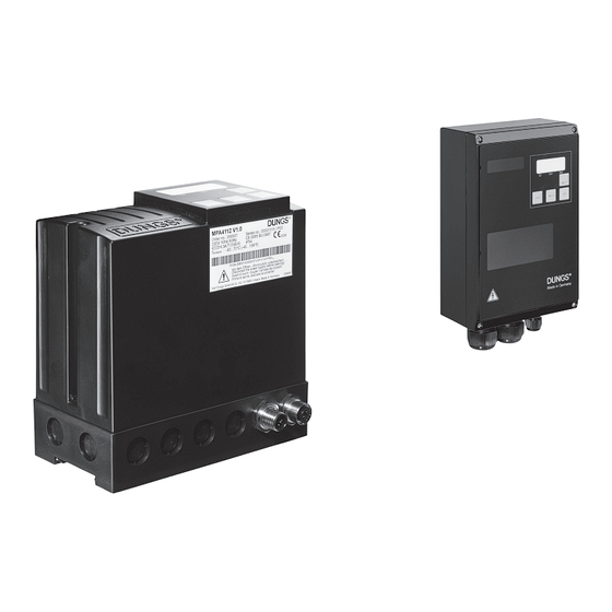
- Page 14 1 MPA 41xx PF system description The MPA 41xx PF is suitable for use with high-speed burners with fast On/Off switching (pulse firing). Flame monitoring is carried out by means of an ionisation input. High temperature operation can be activated using an external switching signal.
- Page 15 Technical data General MPA 41xx PF Protection type MPA 4112 PF IP 54 / NEMA 12 Schutzart Metallgehäuse MPA 4122 PF IP 65 (Attention: use suitable cable screw connections only!) Ambient temperature -40 °C ... +70 °C MPA 41xx PF Storage and transport -40 °C ...
-
Page 16: Connection Diagram
Connection diagram MPA 4112 PF 9 10 11 12 13 14 15 16 17 18 19 20 5A T 6.3A T (10A F) * The connection cables used must be suitable for an ambient temperature of at least 75 °C (167 °F) Connection diagram MPA 4122 PF 9 10 11 12 13 14 15 16 17 18 19 20 5A T... - Page 17 Technical data Outputs Designation Connec- Safety- Type of output Line length Electrical data tion X related Relay contact Max. 100 m For 250000 switching cycles: Safety valve 115/230 VAC / 2 A cos ϕ = 1 For 2.5 million switching cycles: 115/230 VAC / 1 A cos ϕ...
- Page 18 Inputs Designation Connec- Safety- Type of output Line length Electrical data tion X related Contact Contact PE/Earth Contact Input safety chain Contact Max. 100 m 115/230 VAC / max. 5 A (from L1, se- cured via fuse in fuse holder) Flame detector Ionisation for Max.
- Page 19 Technical data General information Designation Type of input Electrical data L1 connection over exchangeable 6.3 A slow-blow or 10 A fast-blow backup fuse Safety chain connection via exchangeable 5 A slow-blow backup fuse in the fuse holder TWI interface Connection only for VisionBox and param- eter setting box NOT galvanically isolated! Switch for parameterisation mode...
-
Page 20: Flame Detection/Flame Detector Connection
15: Ignition Flame 3: N 4: PE 5: ION* 7: FLW power *When using a DUNGS DEZ 1xx SEO ignition transformer for single-electrode operation, the green/yellow cable must be connected to terminal 5. Two-electrode operation ionisation MPA connection 15: Ignition Flame... - Page 21 MPA 41xx PF installation MPA 4112 PF installation options: - Direct screw connection of the base to the installation surface Break off installation holes using, for example, a suitable screwdriver or bore them using a drill 4.2 mm (M4) or 5.5 mm (M5). - Hat rail mounting (locking the base into place on a hat rail) Hat rail...
- Page 22 Dimensions MPA 4112 PF 152.5 22 … 96...
- Page 23 Installation of the MPA 41xx Installation options for the MPA 4122 PF: - direct screw connection of the housing on the installation surface using M4 screws, length min. 20 mm Dimensions of the MPA 4122 PF 37,9 40,5 M16x1.5 - 6H M16x1.5 - 6H M16x1.5 - 6H M32x1.5 - 6H...
-
Page 24: Description Of The Functions
Key con- tion firmation The waiting time is 15 minutes or 3 min- required utes for each unlocking. Dungs Extended unlocking The described limitation to 5 unlocking Expert operations in 15 minutes can be reset by means of "Extended unlocking". To... -
Page 25: Flame Detector
Once all parameters are set, all values Gas valve V1 X13 must be confirmed once again. This The gas valve V1 switches depend- ing on the state, see line V1 in the flow completes setting the parameters (H5 is displayed) and the parameter switch chart. - Page 26 26 … 96...
- Page 27 27 … 96...
- Page 28 State description MPA 41xx PF State xx Designation Description If the automatic system is in this state, there is an error. Error (Fxx) The display automatically shows an error message and indi- cates the current error (e.g. "F 11") instead of the state num- ber.
- Page 29 State description MPA 41xx PF State xx Designation Description The flame may not be detected within the state time of max. 1 External light monitoring (A1) min. Otherwise, the automatic system tries to restart. As of this state, the air valve is active and cannot be deacti- vated via the bus.
- Page 30 State description MPA 41xx PF State xx Designation Description In this state, the system waits until parameter P52 is finished; Restart protection (A4) this prevents an immediate restart of the automatic system if a heat request is active. The flame may no longer be detected in this state;...
- Page 31 State description MPA 41xx PF State xx Designation Description The HT mode can stabilise in this state. The duration of this HT stabilisation (b2) stabilization phase is configured via P89. If from this state on the heat request ceases to exist again, the HT post-venting is activated.
-
Page 32: Parameters/Parameter Change
Parameter Parameter change Parameter types 1-bit parameter (U1) - setting 0 and 1 (displayed as ON/OFF), no limits 8-bit parameter (U8) - value setting within variable limits 16-bit parameter (U16) - value setting within variable limits. A parameter may be modified on the display of MPA or via the VisionBox software on a PC. -
Page 33: Parameters/Parameter Description
Parameter Parameter description Parameter Designation Description Setting / Examples Field bus address Setting the bus slave address of MPA Value range: configuration If an invalid address for the connect- OFF (no fieldbus available) ed bus module is set and the MPA is 1 to 254 in automatic mode, it restarts (error (e.g. - Page 34 Parameter Parameter description Parameter Designation Description Setting / Examples Air pressure switch: The air pressure monitoring can be e.g. monitoring desired for Operating mode made in eight different state ranges. • Idle state control • Idle state control flame mode Flame mode = 1 (state 6) •...
- Page 35 Parameter Parameter description Parameter Designation Description Setting / Examples Temperature controller This parameter can be used to con- Setting 0: operating mode figure the behaviour of the MPA and Only the hardware input Heat request the way it accepts the heat request is active, the bus signal Heat request via bus or via the HW input Heat re- is ignored.
- Page 36 Parameter Parameter description Parameter Designation Description Setting / Examples Operating mode X17 This parameter defines whether HT Setting 0: Input has no function, the mode is used, a gas pressure switch HT mode is deactivated. is connected or a Proof of closure Setting 1: contact (POC).
- Page 37 Parameter Parameter description Parameter Designation Description Setting / Examples Duration safety This parameter can be used to define Value range: chain open the duration of state 25 (safety chain 0 to 65534 (resolution in 1/16 s). open). Time until the automatic sys- 65535: Infinite state duration tem restarts or changes to lockout, depending on the anti-oscillation...
- Page 38 Parameter Parameter description Parameter Designation Description Setting / Examples Extraneous light Defines the duration of the after-burn Value range: time (state 17), the time metering 16 to 65534 (resolution in 1/16 s). starts already during the post-vent- ing (state 16). That means that if the after-burn time is shorter/equal to the post-venting time, the state after-burn time is...
- Page 39 Parameter Parameter description Parameter Designation Description Setting / Examples Self-test Since the MPA41xxPF is an intermit- Setting 1 to 1439 (resolution in 1/16 tent automatic system, a self-test must be carried out every 24 h (jump to state 3 and internal self-test). This parameter can define a time at which the MPA is to perform a premature, voluntary self-test if it...
- Page 40 Parameter Parameter description Parameter Designation Description Setting / Examples Maintenance interval A counter counts the reactions of the Setting 1 to 65534 (resolution 1000). watchdog relay in state 5 (watch- dog loading phase). If the counter reaches the value defined in param- eter P92*1000, a message is output via field bus (see chapter Input data of the master from the MPA)
- Page 41 Parameter Parameter description Parameter Designation Description Setting / Examples P241 Bit functions priority Bit 0: OFF = heat request overwrites switching ventilation request, the MPA starts Cooling/heating operation despite the ventilation request ON = ventilation request overwrites heat request If ventilation request is set (only via bus possible) in operation, the MPA shuts down in a regular way and waits for heat request with ventilation...
- Page 42 Parameter Factory settings Para- Designation Factory Unit Access Comfort Min. value Max. value meter setting level parameter setting Field bus ad- 255 = OFF OPERATOR dress configura- tion Number of re- start attempts or anti-oscillation counter Number of restart attempts when flame is missing after the start-gas flame...
- Page 43 Parameter Factory settings Para- Designation Factory Unit Access Comfort Min. value Max. value meter setting level parameter setting Operating mode SERVICE output X14 Anti-oscillation SERVICE counter for flame detection during HT mode Self-test 1380 min. SERVICE 1439 Duration of 1/16 s SERVICE 9600 switch-on delay...
- Page 44 Status information MPA 41xx PF Designation Description displayed displayed VisionBox display General information Fault switch-off Automatic system is locked ● Current state of the automatic system, key combination + ● 7-segment State number and - Current access level ● Flame Flame detected ●...
- Page 45 Status information MPA 41xx PF Designation Description displayed displayed VisionBox display Cycl. state counter Counts in 1/128 s cycle ● Processor load ● Nominal modulation degree No function ● Actual modulation degree No function ● LED: Indicated by one of the 3 LEDs on the display 7-segment: Indicated by one or several characters of the 7-segment display Info: Displayed in informative display mode 45 …...
- Page 46 Display The customer may customize the MPA 41xx PF on the integrated display to match the desired burner. All important parameters may be set by means of the four operating keys. The parameters of the device are either set by means of VisionBox or by means of the parameterisation and service box.
-
Page 47: Mpa 41X2/Overview Of The Display Modes
Overview of the display modes Mode Active Operation display in normal operation if no error is active. Error display if the automatic system is in fault lock. Info display From operation display by pressing a shortcut Display of the error memory From operation display by pressing a shortcut Parameterisation display From operation display by pressing a shortcut... - Page 48 Display ▶ Displayed operating state for setting parameters and troubleshooting Character blue Heat Flame Fault request yellow blue Attention Observe indication on 7-segment display 1. Digits 2. Letters B or b = D or d = O or o = 48 …...
- Page 49 11.7 Operating state Operation display MPA 41xx PF ▶ Shows the operating state of the automatic system Safety chain open State 35 Safety chain Safety chain closed closed with open safety chain Switch-on delay until test terminals 11&14 state 2-4 Gas pressure with insuffi cient gas present...
-
Page 50: Mpa 41X2/Operation Display
Operation display Operation display additional information ▶ Display of state number ▶ Display and setting the bus address Press the keys simultaneously to change the state display Display of state number Operation display Display of bus address while pressing a key Display of bus address or OFF Back to operation display... -
Page 51: Mpa 41X2/Operation Display Parameterisation And Service Box
Operation display Operation display / parameterisation and service box ▶ Display of the automatic system state during parameterisation or checking in the service box Parameters are loaded from the parameterisation and service box into MPA The MPA is in test mode initialised by the param- eterisation and service box. -
Page 52: Mpa 41X2/Info Display
Info display Info display The information display is activated out of the operation display (not during automatic parameter ▶ setting). The information display allows you to see the fl ame quality, the resettable runtime meter, the resettable ▶ start counter and the switching cycles counter. ▶... -
Page 53: Mpa 41X2/Error Display
Error display Error display An error message is automatically displayed as soon as the automatic system goes to the fault lock ▶ position. ▶ The last occurred error is displayed. F1 to F9 are also displayed in standby and operation. F5 to F9 can be acknowledged by pressing ▶... - Page 54 Display of the error memory Display of the error memory ▶ The display of the error memory is used to call the last 10 errors. ▶ The error that has occurred last is displayed. The error memory display is activated out of the operation display (not during parameterisation dis- ▶...
- Page 55 Parameterisation display Parameterisation display After activating the automatic parameter setting, 19 parameter values must be defined; see parameter ▶ list. ▶ This parameterisation is quit after 30 min. due to a timeout. ▶ A password is required for changing the parameters. Attention: Some parameter values are displayed in another resolution than in the parameterisation ▶...
- Page 56 Parameterisation display ▶ Attention: Press the "Back" button to return to previous steps in the parameterisation mode. Parameter switch to "Para", power supply "On" Password entry Password entry 1. character Password entry 2. character fl ashing (30 s timeout) fl ashing (30 s timeout) 56 …...
- Page 57 Parameter 0 (P30) Pre-venting time (0-99 s / 1 s) Parameter 1 (P31) Pre-ignition (0-99 s / 1 s) Parameter 2 (P32) First safety time for start-up (1-15 s / 1 s) Parameter 3 (P12) Number of restart attempts (0-5) 57 …...
- Page 58 Parameter 4 (P34) Stabilisation time A (0-99 s / 1 s) Parameter 5 (P83) Duration of switch-on delay after voltage on (0-99 s / 1 s) Parameter 6 (P41) Operation safety time for fl ame detector 1 (0.75-3.5 s / 0.1 s) Parameter 7 (P85) Pre-venting time HT mode (0-99 s / 1 s)
- Page 59 Parameter 8 (P51) Post-venting time fl ame (0-99 s / 1 s) Parameter 9 (P14) Number of permitted restarts after fl ame lift-off dur- ing operation (0-5) Parameter A (P13) Number of permitted restarts after missing fl ame (0-5) Parameter b (P15) Locking after opening the safety chain 0 = No (Off ) 1 = Yes (On)
- Page 60 Parameter C (P16) Operating mode of the air pressure switch (0-99) Parameter d (P18) Input X17 (0-3) Parameter E (P87) Duration voltage on after operating mode HT (1-99 / 1 s) Parameter h (P17) Operating mode Temperature controller (0-4) 60 … 96...
- Page 61 Parameter L (P19) Output operating mode (0-11) Restart protection parameter (P52) Duration of the restart protection operating mode fl ame (0-99 s / 1 s) Parameter n (P11) Fieldbus address (0- 99, do not set "0") (Press + and - If value(s) are changed back to together parameter 0...
- Page 62 Reset display Reset display ▶ The reset display is activated out of the operation display (not during automatic parameter setting). The reset display can be used to delete the error memory, the access level, the resettable runtime ▶ meter, the start counter or switching cycles counter and to change the passwords for the service and OEM level.
- Page 63 Entry of the previous password 1. character Entry of the previous password 2. character Correct Incorrect password password Back to operation display Entry 1. character Entry 2. character Display of new password Display of new password operation display 63 … 96...
-
Page 64: Mpa 41Xx Errors Without Error Id
Error overview MPA 41xx PF errors without error ID Error Internal Error description error Please see the tables above for more information about the individual errors. Low voltage flashing Internal error Internal error display flashing The password has been entered incorrectly when trying to change it or has not been confirmed by means of the unlock key flashing The signal of the remote unlocking via bus is active for too long... - Page 65 Error overview MPA 41xx PF Errors from the basic system (0x01 to 0x3F) Error Internal Error description error 0x01 0x02 INTERNAL ERROR: WATCHDOG Possible cause of the error: 0x03 Too high ambient temperature Overvoltage LOCK-OUT RELEASE DENIED Possible cause of the error: 0x04 More than 5 unlocking operations in the last 15 minutes, remedy: Wait or carry out an extended unlocking...
- Page 66 Error overview MPA 41xx PF Error Internal Error description error ERROR FROM EXTERNAL APPLICATION Possible cause of the error: Timeout of parameter mode/manual mode (0.5 h without pressing a key) - detail error 4. Byte = 0xA0 An invalid fieldbus address has been entered in P11 for the connected bus module. Detail error 4.
-
Page 67: Errors From The Application
Error overview MPA 41xx PF Errors from the extended functions (0x40 to 0x9F) Error Internal Error description error 0x40 - reserved 0x42 0x43 0x44 - reserved 0x55 0x56 0x57 - reserved 0x58 INTERFACE P2 Possible cause of the error: 0x59 The bus connection has been interrupted and the parameter P17 has been configured in a way that a bus interruption triggers a safety shutdown followed by a fault lock, see P17: Temperature controller operating mode... - Page 68 Error overview MPA 41xx PF Errors from the application (from 0xA0) Error Internal Error description error EXTRANEOUS LIGHT UPON STARTUP Possible cause of the error: Earth connection to an ionisation electrode 0xA6 Gas flows out and is burned for example by neighbouring burners Defective UV tube Connected flame detector (UV, ...) detects light or is defective NO FLAME DURING SAFETY PERIOD...
-
Page 69: Annex
Annex Setting the bus address, bus termination ....................66-67 Profibus ................................68-72 Modbus ................................73-81 Flame detector ..............................82-83 UV 41 (HE)................................ 84-85 Ignition transformers ............................86-88 VisionBox ................................89 69 … 96... - Page 70 Setting the fieldbus address Important: Any modifications are ap- If an invalid address for the connected If you want to connect the automatic plied after a restart or an extended bus module is set and the MPA is in au- system to the bus, a valid address tomatic mode, it restarts (error 0x18).
-
Page 71: Profibus
Extension module MPA 41xx EM 2/4 Profibus termination The output data have 8 bits, see table Profibus DP interface, Modbus RTU / ASCII DIP switches No. 2 and 3: Output byte AB0 Heat request Universal extension module for inte- ON position = Profibus termination 220 grating the MPA 41xx PF in fieldbus Ohm. - Page 72 Profibus input data MPA to master Input data is information about the state of the MPA. The input data contain a different number of bytes, depending on the data transfer module used. The lower bytes are always the same, i.e. Basic transfer is included in Standard transfer, Standard transfer in Extended transfer.
- Page 73 Basic transfer area MPA 41xx PF Input byte EB0 Description During fault Flame input Input HT Input HT NC / Gas pressure switch / POC Warning flame Flame detected in the HT mode in HT Input Air pressure switch X18 Input for temperature controller Output valve 1...
- Page 74 Standard transfer area MPA 41xx PF Input byte EB2 Description During fault State number or error Current state number or error code if there is a fault code Input byte EB3 Description During fault Flame quality Quality of the flame via ionisation input Extended transfer area MPA 41xx PF Input byte EB4...
- Page 75 Special Extended transfer area MPA 41xx PF Input byte EB12 Description During fault Maintenance counter Low byte (byte 0) of the 16-bit maintenance counter, Resolution 1000 switching cycles Input byte EB13 Description During fault Maintenance counter High byte (byte 1) of the 16-bit maintenance counter, Resolution 1000 switching cycles Input byte EB14 Description...
- Page 76 Declaration of the Profibus interface MPA 41xx PF Manufacturer identification ID number OxOCF1 (Karl Dungs GmbH & Co. KG) ASCIC type VPC3+C Is supported Sync and freeze mode (Sync command: Freeze all outputs of the addressed slaves Freeze command: Freeze all inputs of the addressed slaves)
- Page 77 Modbus data Bit 3 If bit 3 is set to 1 by master, the Modbus RTU or ASCII mode output X11 is switched on (P19=11). The modbus protocol can be switched Bit 4-15 not used over to ASCII mode using the function code 0x41.
- Page 78 Register address 0 Description During Fault Flame input Input HT Input HT NC / Gas pressure switch / POC Warning flame in HT Flame detected in the HT mode Input Air pressure switch Input for temperature controller (HW) Output valve 1 V2 boost / energy int.
- Page 79 Register address 5 Description During Fault Resettable runtime meter for Byte 1 of the 32-bit runtime meter (in s) flame and HT 8...15 Not used Not used Register address 6 Description During Fault Resettable runtime meter for Byte 2 of the 32-bit runtime meter (in s) flame and HT 8...15 Not used Not used...
- Page 80 Register address 15 Description During Fault Maintenance counter air valve High byte (byte 1) of the 16-bit maintenance counter, Resolution 1000 switching cycles 8...15 Not used Not used Register address 16 Description During Fault Maintenance counter Low byte (byte 0) of the 16-bit maintenance counter, Watchdog relay Resolution 1000 switching cycles 8...15 Not used...
- Page 81 Register address 22 Description During Fault State number or Current state number OR error code if there is a fault Error code 8-15 Flame quality Quality of the flame via ionisation input Register address 23 Description During Fault Resettable Low byte (byte 0) of the 32-bit runtime meter (in s) Runtime meter for flame and 8-15 Resettable...
- Page 82 Register address 26 Description During Fault Resettable start counter Byte 2 of the 32-bit start counter for flame operation 8-15 Resettable start counter High byte (byte 3) of the 32-bit start counter for flame operation Register address 27 Description During Fault 0-15 Maintenance counter V1...
- Page 83 Register address 38 Description During Fault Article number HW Byte 0 (low byte) of the 24-bit article number 8-15 Article number HW Byte 1 of the 24-bit article number Register address 39 Description During Fault Article number HW Byte 2 (high byte) of the 24-bit article number 8-15 Index article number HW e.g.
- Page 84 Register address 49 Description During Fault Article number HW-EM Byte 2 (high byte) of the 24-bit article number 8-15 Index article number HW-EM e.g. 0x5F="_"; 0x41="A", 0x42="B" … Register address 50 Description During Fault Article number device EM Byte 0 (low byte) of the 24-bit article number 8-15 Article number device EM Byte 1 of the 24-bit article number...
- Page 85 Line lengths Designation Line length Electrical data Profibus DP Max. 1200 m Galvanically isolated 4kV Modbus Max. 1000 m Galvanically isolated 4kV Supported baud rates Profibus The following table is only valid for line type A to EN 50170 Transfer speed 19.2 45.45 93.75...
-
Page 86: Flame Detector
MPA 41xx PF and the flame detector must be connected according to the correct phase. Attention DUNGS cannot be held liable if the flame detector and the automatic burn- er control system do not work orderly together. Especially if the electromag-... - Page 87 Ionisation Ionisation Ionisation – electrode UV tube Ionisation 0.125 s P41 + 0.125 s Yes DUNGS UV41 (HE) (= 2/16 s) Flame detectors that are not included in this list must be authorised before use by DUNGS. 87 … 96...
- Page 88 UV 41 (HE) The UV 41 (HE) is a flame detector with UV tube in metal design for high mechanical stress. The flame detector is connected to the ionisation input of the MPA 41xx PF and is suitable for intermittent opera- tion.
- Page 89 Mounting The UV 41 (HE) must be mounted as closely as possible to the flame to be monitored. For mounting the UV41 on the burner a suitable EM1/x adaptor is required. When mounting it, make sure that the rubber sealing ring enclosed with the UV 41 (HE) is inserted between the UV 41 (HE) and the mounting adapter.
-
Page 90: Ignition Transformers
DEZ ignition transformers Technical description The DUNGS DEZ are electronic high- performance ignition transformers with high-frequency oscillation technology. Compared with conventional induc- tive ignition transformers, the DEZ are much smaller and lighter. Designs for one or two ignition elec- trodes are available in different voltage versions. - Page 91 DEZ function Both versions are available with differ- ent performance data. The DEZ ignition transformers are For use in burner systems in which available in two versions. ignition and ionisation flame monitoring Either with a high-voltage output (DEZ takes place via a common electrode, 1xx) for ignition against the burner the "SEO"...
- Page 92 Electrode connection DEZ connection ø 6.3 mm Dimensions Attention The operation of the DEZ ignition transformers produces very high volt- ages. The ignition transformers may only be put into operation if the ignition electrodes were built into the burner / burner chamber touch-proof and all live connections by means of the lines provided for this purpose were made touch-proof.
-
Page 93: Visionbox
VisionBox The VisionBox is used for access to the MPA via a PC. www.dungs.com/softwaretools 93 … 96... - Page 94 94 … 96...
- Page 95 95 … 96...
- Page 96 Karl Dungs GmbH & Co. KG Siemensstraße 6-10 D-73660 Urbach, Germany Phone +49(0)7181-804-0 +49(0)7181-804-166 info@dungs.com www.dungs.com 96 … 96...
Need help?
Do you have a question about the MPA 41 PF Series and is the answer not in the manual?
Questions and answers