Advertisement
- 1 Overview
- 2 What's in the Box
- 3 Mounting Instructions
- 4 Front and Back Panel
- 5 Display Screen
- 6 Navigation and Controls
- 7 Menu Map
- 8 System Examples
- 9 Antenna Configuration
- 10 Networking
- 11 Frequency Coordination
- 12 Scan Tools
- 13 Management and Monitoring
- 14 Setting the Date and Time
- 15 Locking and Unlocking the Controls
- 16 Headphone Settings
- 17 Adjusting the Display
- 18 Cooling Fan Settings
- 19 Troubleshooting
- 20 Event Log
- 21 Firmware Updates
- 22 Factory Reset
- 23 Glossary
- 24 Specifications
- 25 IMPORTANT SAFETY INSTRUCTIONS
- 26 Documents / Resources
Overview
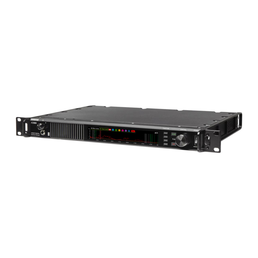
The Shure AD600 Digital Spectrum Manager is a powerful tool for planning and managing frequency coordination. Use the guided coordination features to plan, scan, and deploy frequencies to your entire system. Additional tools are available to analyze the spectrum, capture data, and monitor audio from compatible devices on your network.
The AD600 is a single-tool solution to manage the RF spectrum:
- Advanced, comprehensive frequency coordination for your network
- Fast, real-time scanning to find available frequencies and monitor RF activity
- Large, 6.6-inch (16.75 cm) color display for viewing and analyzing the RF spectrum
- Guided frequency coordination to save time and effort in challenging RF environments
- Tools for viewing, analyzing, and listening to frequency activity
- Tuning range: 174 MHz to 2 GHz for support of multiple frequency bands
- 6 antenna connections to support multiple devices and increase coverage options
- Data capture and storage to archive RF information for analysis
- Network enabled for large-scale system deployments
- USB connection for external data storage of scans, event logs, and other data
- Dante enabled for advanced audio monitoring of your network
- Compatible with Wireless Workbench to extend control and monitoring options
What's in the Box
- AD600
- Power cable with V-Lock (region specific)
- USB extension cable
- Rack mount hardware kit (90YT1371)
Mounting Instructions
This component is designed to fit into an audio rack.

To prevent injury this apparatus must be securely attached to the rack.

Front and Back Panel

- Headphone volume knob
Controls headphone volume. Clip indicator warns of signal overload. Press knob to access Dante options and headphone settings. - Monitor jack, headphone jack
¼" (6.35 mm) audio output jack. - Display
Color display to view and analyze RF spectrum. - Function buttons
Press to access editing and configuration options. The buttons are named F1, F2, F3, F4 (from top to bottom) and illuminate when options are available. - ENTER button
Press to save changes. - EXIT button
Press to cancel changes and return to previous menus. - Control wheel
- Push to access a menu
- Push to select parameters or menu items
- Turn to scroll through menu items or to edit a parameter value
- Power switch
Powers the unit on or off. - AC power input
IEC locking connector, 100-240 V AC. - AC power cascade (locking)
Use IEC extension cables to cascade power through multiple devices. - Ethernet ports
Four Ethernet ports carry the following signals:- ctrl 1: Network control; supports PoE
- ctrl 2: Network control; supports PoE
- Dante primary: Dante digital audio
- Dante secondary: Dante digital audio
- Network status LEDs
- Off: no network link
- On green: network link active
- Flashing green: network link active, rate corresponds to traffic volume
- Flashing amber: indicates the connection is 1 Gbps, rate corresponds to traffic volume
- USB port
Transfer recorded scan data to and from external storage devices. - Antenna bias indicator LED (one per antenna)
- Green: Antenna bias enabled
- Red: Antenna fault
- Off: Antenna bias disabled
- Coaxial inputs for antennas A, B, C, D, E, F
RF connection for antennas A, B, C, D, E, F. - Cooling vents
Vents on the front and rear for cooling.
Display Screen
The home screen displays RF activity for each antenna. From this screen you can access the main menu and the scan tools. Use the control wheel to navigate to the menu choices or to turn the antenna plots on or off.

Note: These options are visual only and don't affect coordination or backup frequency monitoring.
- Main menu: Access to the main menu
- Scan tools: Access to scan tools
- Scan status: Indicates if current view is a live scan or a saved file
- Antennas A-F: Each antenna is color coded on the RF plot
- Max: Combines the real-time peaks from all antennas into a single plot
Icon Key
| Icon | Description |
 | USB: Appears when a storage drive is attached to the USB port. Select the icon to see more information and eject the USB drive. |
 | Alarm: Appears when one or more hardware alarms are present. Select the icon to see any active alarms. |
 | Power switch lock: Prevents accidental shutoff. When the power lock is activated and the power switch is toggled, the AD600 remains on. |
 | Front panel lock: Prevents menu changes. When the control lock is activated, menu options can't be edited. |
 | Access control: Appears if access control is enabled. |
 | Network status indicator: Appears if the AD600 sees other devices on the network. |
Navigation and Controls
Use the function buttons, control wheel, ENTER, and EXIT to navigate to menu choices and to set parameters.

- Function buttons
Press to access editing and configuration options. The buttons are named F1, F2, F3, F4 (from top to bottom) and illuminate when editing options are available. - Control wheel
- Push to enter a menu
- Push to select a menu item
- Turn to scroll through menu options or to edit a parameter
- ENTER
Press to confirm or save changes. - EXIT
Press to cancel changes and return to main menu.
Menu Map

System Examples
Single Frequency Band System
In this example, all devices connected to the AD600 operate in the same frequency range:

- Set the AD600 antennas to match the frequency range of each connected receiver.
- Additional receivers operating in the same frequency range can be added to the network to expand the system.
Tip: Connect the receiver antenna cascade ports to the antenna inputs of the AD600.
Multiple Frequency Range System
In this example, the AD600 is supporting receivers operating in different frequency ranges.

- Set the AD600 antennas to match the frequency range of each connected receiver.
- Additional receivers operating in the same frequency ranges can be added to the network to expand the system.
Tip: Connect the receiver antenna cascade ports to the antenna inputs of the AD600.
Antenna Configuration
The AD600 uses up to 6 antennas to support multiple frequency bands and provide greater coverage for complex systems.
Antenna Ports
The AD600 has 6 antenna ports on the rear panel. Each port can be configured to match the bandwidth of the connected antenna. Bias power can be turned on when using active antennas.
Setting Antenna Parameters
Once you have connected your antennas, you can set the antenna parameters. For example, if your gear operates in a range of 470-534 MHz, choose the appropriate antennas and set the range to 470-534 MHz.
Tip: Set the configuration mode to Paired to set parameters for a pair of antennas (AB/CD/EF).

- Main menu > Device Configuration > Antennas
- Enable the antennas. Choose View only if you want to display the RF activity and don't plan on using the antenna data in a frequency coordination.
- Choose a preset range or select a range manually to match the antenna bandwidth.
- If using an active antenna, set the Bias to On.
Note: When using active antennas Total Current appears in the configuration window.
Antenna Configuration Examples
The following examples are common antenna configurations for the AD600.
Wideband coverage
Wideband coverage supports gear in different frequency bands. Antennas are configured to match the frequency range of each group of devices. In this example, there are 3 pairs of antennas placed to support devices operating in 3 different frequency ranges.

Large area coverage
Large area coverage is used in venues such as convention spaces or sports arenas. Antennas are placed strategically to provide RF coverage for the space and minimize dead spots.

Linear or parade route coverage
Linear coverage is used in areas such as long hallways, runways, or roads. Antennas are spaced to prevent gaps in coverage along the route.

Networking
The AD600 features a 4-port network interface. Dante technology provides an integrated solution to monitor digital audio. Dante uses standard IP over Ethernet and safely coexists on the same network as IT and control data. Selectable networking modes route port signals for flexible network setup.
Network Signal Types
The following signal types are supported on the network:
- Shure control: Shure Wireless Workbench software provides comprehensive control for wireless audio systems
- Dante primary: Dante digital audio signals
- Dante secondary: Second copy (redundant) of the Dante primary audio, often used for additional routing options
Guided Network Configuration
The AD600 offers guided setup to simplify networking of your gear.
Setup includes the following:
- Switch mode
- Shure control
- Dante primary
- Dante secondary
Networking Modes
The networking mode determines the type of signals that are routed to the ports.

Switched Mode Port Signals
- Shure control and Dante primary
- Shure control and Dante primary
- Shure control and Dante primary
- Shure control and Dante primary
Split/Redundant Mode Port Signals
- Shure control
- Shure control
- Dante primary
- Dante secondary
Setting the Switch Mode
- From the main menu: Device Configuration > Network Settings > Setup.
- Use the control wheel to set the switch mode to Switched or Split Redundant.
- Press ENTER to save and reboot.
Setting the Interface Mode (IP Address)
An IP address must be assigned to each device in the network to ensure communication and control between components. Valid IP addresses can be assigned automatically using a DHCP server or manually from a list of valid IP addresses. If using Dante audio, a separate Dante IP address must also be assigned to each Dante device.
Automatic
- If using a DHCP capable Ethernet switch, set the DHCP switch to ON.
- From the Device Configuration menu: Network Settings > Setup > Next
- Use the control wheel to set the Interface Mode to Automatic for Shure Control, Dante Primary, and Dante Secondary (if applicable).
- When finished, use the Back button to return to the home screen.
Manual
- From the Device Configuration menu: Network Settings > Setup > Next
- Use the control wheel to set the Interface Mode to Manual.
- Set valid IP addresses, subnet values, and gateways, for Shure Control, Dante Primary, and Dante Secondary (if applicable).
- When finished, use the Back button to return to the home screen.
Network Browser
Use the network browser tool to view Shure devices on the network. Access the tool from Main menu > Device Configuration > Network Browser and use the control wheel to select a device.

Identify All
Flashes the front panel LED of all devices on the network to verify connectivity.
Refresh
Updates the device list.
FW Version
Displays the firmware versions of devices found on the network. Select Model to view the device model.
Tip: Press the control wheel to view the device IDs and IP addresses of these devices.
Frequency Coordination
The AD600 offers guided frequency coordination to simplify the process of finding frequencies for your system.
Two options are available for setting up or modifying a coordination:
- Regular coordination, which works in most situations
- Advanced coordination, which offers more control over parameters for more complex situations
Create or Modify a Coordination
To begin a coordination, go to Main menu > Freq Coordination and choose to create a new coordination or modify an existing coordination.
Note: Regular coordination is appropriate in most situations. Use the advanced option or Wireless Workbench if you need to add virtual channels, manually set exclusions or thresholds, or otherwise customize your coordination.
Follow the prompts and choose Next to move through each step.
Step 1: Choose devices
Use the control wheel to select devices to include in your coordination.
Step 2: Scan
Select Start scan and monitor the display. Longer scans can provide more data for your coordination. Select Stop scan when the plot has stabilized.
Step 3: Calculate
The AD600 will automatically calculate a frequency coordination for your system. Select Deploy to assign the frequencies to your devices and complete the coordination.
Tip: Re-sync portables if necessary.
Advanced Coordination
Use the advanced coordination option when the regular coordination doesn't meet your needs. In an advanced coordination, you manually set additional parameters such as exclusions, thresholds, user groups, and TV channels.
Tip: You can also use Wireless Workbench for an advanced coordination.
Go to Main menu > Freq Coordination and choose the advanced options to create or modify a coordination. Follow the prompts and choose Next to move through each step.
Step 1: Choose devices
Use the control wheel to select devices to include in your coordination. Add virtual channels if you need to coordinate frequencies for devices that are not on the network.
Step 2: Frequency requests
Select a compatibility level and the desired number of backup frequencies for each device.
Step 3: Exclusions
Select Settings to choose any of the following exclusions:
- Scans: Load scan files
- Thresholds: Set scan peak threshold and exclusion threshold
- TV channels: Set the TV format or load TV data
- Exclusion list: Use the add function to add frequencies and ranges to exclude from calculation
Select Start scan and monitor the display. Longer scans can provide more data for your coordination. Select Stop scan when the plot has stabilized.
Step 4: Advanced options
Select a user group: Choose regional user lists and groups.
Change the coordination order: Move devices to change priority.
Analyze frequency list: Select Analyze to check frequencies for compatibility in your RF environment. Select Lock compat. to lock all compatible frequencies.
Step 5: Calculate
Select Start to calculate frequencies for your system.
Step 6: Assign and deploy
Select Deploy to assign the frequencies to your devices and complete the coordination.
Tip: Re-sync portables if necessary.
Scan Tools
The AD600 includes an array of tools to analyze the spectrum, capture data, and customize your display. Access the scan tools from the tab on the home screen.

Cursor
Cursor places a movable vertical line on the RF plot. Use the control wheel to position the cursor at any point in the plot. The frequency value and signal strength for the selected point are shown next to the cursor.
Zoom
Zoom magnifies the RF plot to allow for detailed analysis of a portion of the spectrum. Use Zoom to identify individual frequencies in crowded RF environments.
Range
Use the control wheel to define the plot limits for the display or select one of the following presets:
- Antenna range: Plot matches the range of the antennas
- Freq list range: Plot matches the frequency list
Capture
The AD600 can scan and store periods of RF activity to provide a record of activity in the RF spectrum. Scan files can be saved for later reference or loaded for advanced frequency coordination.
Open scan
Use the control wheel to load saved or captured scans from the internal drive or USB drive.
Live scan
Returns the display to show real-time scan activity if you are viewing a saved file.
Listen
Listen to RF activity in the spectrum using headphones. Use the control wheel to select an antenna and to define the signal type.
Save snapshot
Saves the scan data on the current display. Use the control wheel to save the file to a directory or drive.
Markers
Adds color-coded markers on the display to align with in-use frequencies (white), backup frequencies (green), and degraded backup frequencies (red). Use the control wheel to select the types of markers to display.
Management and Monitoring
Monitoring Audio with the Listen Feature
The listen feature allows you to monitor demodulated audio for compatible devices from the headphone jack.

The listen feature can monitor the following signal types:
- Analog FM from Shure products such as Axient Analog, UHF-R, ULX, SLX, BLX, PSM1000, PSM900, PSM300
- Analog FM from non-Shure wireless systems
- Non-encrypted Axient Digital signals (standard and high density)
From the scan tools menu or the frequency list, select Listen. Use the control wheel to select an antenna and to navigate to a point on the spectrum. The frequency number appears next to the cursor.
Listening to Audio using Dante Browse
Use Dante browse to listen to the audio from the Dante-enabled devices on your network.
- Push the headphone knob and choose Dante Browse or go to Main menu > Headphones > Dante Browse.
- Choose Shure to display only Shure devices or All to display any Dante-enabled device.
- Use the control wheel to select a device and channel from the network list.
- Adjust the headphone volume.
Frequency List Monitor
The Frequency list monitor displays devices on the network and the status of their assigned frequencies. Devices on the network appear in the frequency pool along with the status of the frequencies:

- In Use: Frequencies that are assigned to devices
- Ready: Frequencies available as backups
- Degraded: Backup frequencies unavailable because of poor quality
- Zone name: Zone name assigned from Wireless Workbench
You can perform the following tasks from the Frequency list monitor:
- Add pool: Use the control wheel to add and configure devices in the frequency list.
- Edit threshold: Use the control wheel to edit the monitoring threshold that determines when a frequency is considered to be degraded.
- Re-deploy: Use to send new or updated frequencies to all managed channels.
- Clear list: Use to clear frequency list from all devices.
Managing Scan Files
You can save scan data or import scan files from the internal drive of the AD600 or from an external drive connected to the USB port.
Tip: To eject an external storage device, select the USB icon on the home screen and then press the control wheel.
Capturing and Saving Scan Data Files
The AD600 can scan and capture periods of RF activity to document the RF spectrum. Scan files can be saved for later reference or loaded as part of an advanced coordination.

Tip: Use the Save snapshot scan tool to quickly capture the display screen. Snapshots are helpful to capture momentary events or document a point in time.
- Scan Tools > Capture
- Use the control wheel to choose antennas and set scan parameters. Duration is the length of time the capture runs. Save rate determines how many times data is saved per minute.
- Select Start to begin the capture.
Loading Scan Files and Snapshots
The AD600 can load scan files and snapshots from its internal drive or to an external drive connected to the USB port.
- From the home screen, choose Scan tools > Open scan.
- Use the function buttons to choose the internal drive or USB storage device.
- Use the control wheel to select a file, and then press to load.
Tip: Press the control wheel to access scan tools and choose Live scan to return to live scanning or choose Open scan to load another file.
Setting the Date and Time
The AD600 has an internal clock that adds time stamps to scan files, snapshots, and event log entries.
- Select: Device Configuration > Date and Time
- Use the control wheel to set the date, time, and time zone.
- Press ENTER to save.
Locking and Unlocking the Controls
Use the control locks to prevent accidental or unauthorized changes to controls and settings. The front panel and power switch can be independently locked or unlocked.
- Main menu > Device Configuration > Locks
- Use the control wheel to choose lock options.
- Press ENTER to save.
Headphone Settings
The AD600 includes a headphone jack for monitoring audio signals.
Press the headphone knob or navigate from the main menu: Headphones > Headphone Settings
- Use the volume knob to control the volume of the headphones.
- Adjust the limiter threshold to attenuate audio peaks. The audio limiter default setting is -10dB.
Adjusting the Display
Brightness and sleep time are adjustable.
The following display options are available:
- Brightness: Low, Medium, High, Auto
- Display Sleep (in seconds): 10, 30, 60, Off
Note: Sleep will only activate from the home screen.
- Select: Device Configuration > Display
- Use the control wheel to set the brightness or to set the sleep time.
- Press ENTER to save.
Cooling Fan Settings
- From the Device Configuration menu: Fan
- Select from the following fan setting options:
- Auto: Automatically turns on to regulate the temperature
- On: Runs continuously to offer maximum cooling in warm environments
Tip: View the internal temperature on the screen.
Troubleshooting
Use only one DHCP server per network.
All devices must share the same subnet mask.
All devices must have the same level of firmware revision installed. Look for the network icons on the display of each device:
- If the icon is not there, check the cable connection and the LEDs on the network jack.
- If the LEDs are not on and the cable is plugged in, replace the cable and recheck the LEDs and network icon.
Use the Find All utility (Util > Network > Find All) to view devices on the network:
- The Find All report lists all devices on the network.
- Check the IP address for devices not shown in the Find All report to ensure that they are on the same subnet.
To solve network issues related to Wireless Workbench, see the Networking section of the Wireless Workbench help system.
Event Log
The event log records the actions of the Spectrum Manager and the devices it manages. Each event contains an ID, timestamp, category, and description to help with troubleshooting. The log stores up to 9999 events. The most recent events appear at the top of the log. When the storage limit is reached, the oldest events are overwritten.

Use the control wheel to scroll through events. Use the function keys to export the log or to clear the log.
Note: Log entries are not affected by power cycles.
Firmware Updates
Firmware is embedded software in each component that controls functionality. Periodically, new versions of firmware are developed to incorporate additional features and enhancements. You can install firmware using Shure Update Utility.
Download Shure Update Utility at shure.com.
Factory Reset
To restore all parameters to factory settings:
- Main menu > Device Configuration > Factory Reset
- Select ENTER to restore factory settings.
Glossary
Access control
Allows for the assignment of PINs, which protect against unauthorized access to networked components from a computer running Wireless Workbench or other Shure control software.
Backup frequency
A frequency that is compatible with the RF environment and isn't assigned to a device. A backup frequency can be deployed in the event of interference. Frequency statuses:
- In use: A frequency that has been allocated to a device.
- Ready: A backup frequency that is ready to be used.
- Degraded: A backup frequency that is not suitable for use and is unavailable to be deployed. Compatible frequency
A frequency that does not conflict with other frequencies being used in your environment.
Compatibility level
Adjusting the compatibility level allows you to dictate the spacing between synthesized frequencies and other frequencies, including intermodulation products. Sometimes called compatibility settings or compatibility profiles. There are 3 compatibility levels:
- Standard: Uses the default channel spacing. Use this setting to achieve a balance between robust operation and number of frequencies.
- Robust: Uses large spacing between frequencies to avoid interference. Because this setting requires the greatest spacing between frequencies, fewer frequencies will be available in a given amount of spectrum compared to the Standard or More frequencies settings. If enough frequencies can be found, this is the best option.
- More frequencies: Uses narrower spacing to assign more frequencies. Use this setting when the greatest possible number of frequencies is needed. Because this setting allows the closest spacing of frequencies, the working ranges of the systems using them may be more limited, including transmitter to receiver antenna distance and minimum transmitter to transmitter distance.
Equipment profile
A group of coordination settings that apply to all devices of a certain make and model. Equipment profiles can be edited in Wireless Workbench. Sometimes called a device profile.
Exclusions
As part of frequency coordination, you can define single frequencies and ranges to avoid in the frequency calculation. These are called exclusions.
Frequency list
A list of available primary and backup frequencies calculated in Wireless Workbench or a Spectrum Manager. Sometimes called a compatible frequency list, or CFL.
Frequency pool
The frequency list is organized into pools, which are groups of frequencies that are compatible with certain devices. Frequencies in a pool share a common device series (ULX-D, QLX-D, etc.), band, and sometimes RF profile, inclusion group, or zone. Because of these commonalities, the frequency server can deploy any frequency from a device's pool to that device.
Frequency server
AD600 and AXT600 act as frequency servers to deploy compatible frequencies to devices and respond to device requests for new frequencies (for example, in the event of interference).
Intermodulation products
Small RF spikes that are a by-product of modulation and can potentially cause interference. Also called intermods, these are extra frequencies that take up space in your spectrum.
Managed device
A managed device is a device served by the Spectrum Manager. Monitor the device list in the Wireless Workbench properties panel to make sure your RF channels are operating on planned frequencies.
Monitoring threshold
The level at which a frequency is considered degraded (not suitable for use). Frequencies above this level are marked as degraded.
Re-calculate
Runs the calculation again to find different frequencies for your devices.
Re-deploy
Delivers coordination changes to your hardware.
RF zones
A tool that helps you maximize the number of available frequencies when you're coordinating RF across multiple areas in a large venue. They are commonly used in sports arenas, campuses, and corporate environments.
RF zones rely on distance between devices to allow for frequency reuse. For example, if you have systems in 2 buildings in separate parts of a campus, you can reuse frequencies as long as there is enough distance between them. Each building would be its own zone in a coordination.
AD600 is set up to manage a single zone. To coordinate multiple zones, use in conjunction with Wireless Workbench.
RSSI
Received signal strength indicator, or how much RF energy is present at a given frequency.
Scan peak threshold
The frequency at which the calculation will assume an active transmitter is present.
Shure control
Software from Shure that allows for control of devices, such as Wireless Workbench.
User groups
Predefined sets of frequencies designed to control where wireless systems can operate within a region or country.
Virtual channel
Virtual channels are created to represent offline devices that you plan to add to your network or non-networkable (and thirdparty) equipment that will never come online. A virtual channel acts as a placeholder during a coordination so that the offline device will have a frequency included for it in a coordination. Sometimes called virtual devices.
Specifications
RF Tuning Frequency Range
174 - 2000 MHz
RF Tuning Step Size
25 kHz / 200kHz
Noise Floor
Resolution Bandwidth
| 25 KHz | -109 dBm, typical |
| 200 KHz | -100 dBm, typical |
Image Rejection
> 90 dB
Spurious Response
< -100 dBm, typical
Dimensions
43.2 x 482.6 x 285.7 mm (1.7 x 19.0 x 11.25 inches), H x W x D
Weight
3.7 kg (8.15 lbs)
Housing
Steel
Power Requirements
110 240 V AC, 50 60 Hz
Current Drain
1.2 A
Operating Temperature Range
-18°C - 50°C (0°F - 122°F)
Storage Temperature Range
-29°C - 74°C (-20°F - 165°F)
RF Input
Connector Type
BNC
Impedance
50 Ω
Maximum Input Level
+10 dBm
Bias Voltage
12 - 13.5 V DC
150 mA maximum per antenna, 450 mA maximum per device
Headphone Monitor Audio Output
Audio Frequency Response
20 Hz - 20 kHz, +/- 3 dB
Configuration
¼" / 6.3 mm connector, unbalanced stereo
Impedance
63 Ω
Maximum Signal Level
350 mW
Pin Assignments
Tip: Audio +, Left: |, Ring: Audio +, Right: |, Sleeve: Ground
Networking
Network Interface
Quad Port Ethernet 10/100/1000 Mbps
Redundant Dante support
PoE supported on the control ports
Network Addressing Capability
DHCP or Manual IP address
DC Module Specifications
DC Input Voltage Range
10.9 - 16V
Maximum DC Input Current
5.5 A
Protection Modes
Reverse Polarity, Over Voltage
Connector Type
4-pin XLR (male)
The shell of the DC inlet XLR connector is connected to Chassis Ground.
Recommended Cable Gauge
| 6 feet or less | 18 AWG (1 mm2) |
| 7 to 15 feet | 16 AWG (1.5 mm2) |
| 16 to 25 feet | 14 AWG (2.5 mm2) |

Total cable length should not exceed 25 feet.
IMPORTANT SAFETY INSTRUCTIONS
- READ these instructions.
- KEEP these instructions.
- HEED all warnings.
- FOLLOW all instructions.
- DO NOT use this apparatus near water.
- CLEAN ONLY with dry cloth.
- DO NOT block any ventilation openings. Allow sufficient distances for adequate ventilation and install in accordance with the manufacturer's instructions.
- DO NOT install near any heat sources such as open flames, radiators, heat registers, stoves, or other apparatus (including amplifiers) that produce heat. Do not place any open flame sources on the product.
- DO NOT defeat the safety purpose of the polarized or grounding type plug. A polarized plug has two blades with one wider than the other. A grounding type plug has two blades and a third grounding prong. The wider blade or the third prong are provided for your safety. If the provided plug does not fit into your outlet, consult an electrician for replacement of the obsolete outlet.
- PROTECT the power cord from being walked on or pinched, particularly at plugs, convenience receptacles, and the point where they exit from the apparatus.
- ONLY USE attachments/accessories specified by the manufacturer.
- USE only with a cart, stand, tripod, bracket, or table specified by the manufacturer, or sold with the apparatus. When a cart is used, use caution when moving the cart/apparatus combination to avoid injury from tip-over.
- UNPLUG this apparatus during lightning storms or when unused for long periods of time.
- REFER all servicing to qualified service personnel. Servicing is required when the apparatus has been damaged in any way, such as power supply cord or plug is damaged, liquid has been spilled or objects have fallen into the apparatus, the apparatus has been exposed to rain or moisture, does not operate normally, or has been dropped.
- DO NOT expose the apparatus to dripping and splashing. DO NOT put objects filled with liquids, such as vases, on the apparatus.
- The MAINS plug or an appliance coupler shall remain readily operable.
- The airborne noise of the Apparatus does not exceed 70dB (A).
- Apparatus with CLASS I construction shall be connected to a MAINS socket outlet with a protective earthing connection.
- To reduce the risk of fire or electric shock, do not expose this apparatus to rain or moisture.
- Do not attempt to modify this product. Doing so could result in personal injury and/or product failure.
- Operate this product within its specified operating temperature range.
Voltages in this equipment are hazardous to life. No user serviceable parts inside. Refer all servicing to qualified service personnel. The safety certifications do not apply when the operating voltage is changed from the factory setting.
- If water or other foreign objects enter the inside of the device, fire or electric shock may result.
- Do not attempt to modify this product. Doing so could result in personal injury and/or product failure.

Documents / Resources
References
Wireless Workbench
Shure: Microphones, Wireless microphones, in-ear monitoring, earphones, headphones
Download manual
Here you can download full pdf version of manual, it may contain additional safety instructions, warranty information, FCC rules, etc.
Download Shure AD600 - Axient Digital Spectrum Manager Manual
Advertisement


Need help?
Do you have a question about the AD600 and is the answer not in the manual?
Questions and answers