
Subscribe to Our Youtube Channel
Related Manuals for Alpha Technologies Cordex HP 48-12kW/480

Summary of Contents for Alpha Technologies Cordex HP 48-12kW/480
- Page 1 Cordex HP 48-12kW/480 Modular Switched Mode Three-Phase Rectifier Technical Guide: 0100020-J0 Effective: 03/2019 Alpha Technologies Ltd.
- Page 3 International: +1-604-436-5547 Copyright Copyright © 2019 Alpha Technologies Ltd. All rights reserved. Alpha is a registered trademark of Alpha Technologies. No part of this documentation shall be reproduced, stored in a retrieval system, translated, transcribed, or trans- mitted in any form or by any means manual, electric, electronic, electromechanical, chemical, optical, or other- wise without prior explicit written permission from Alpha Technologies.
-
Page 4: Table Of Contents
Table of Contents 1. Safety ............................5 1.1 Safety Symbols .......................... 5 1.2 General Safety ........................... 5 1.3 Mechanical Safety ........................5 1.4 Electrical Safety ......................... 6 1.5 Battery Safety ..........................6 2. Introduction ...........................7 2.1 Scope of the Manual ........................7 2.2 Product Overview ........................ - Page 5 6.1 Packing Materials ........................19 6.2 Check for Damage ........................19 6.3 General Receipt of Shipment ....................19 7. Installation ...........................20 7.1 Safety Precautions ........................20 7.2 Tools Required ......................... 20 7.3 Power System Assembly and Mounting ................... 21 8. Wiring ..........................22 8.1 Grounding ..........................
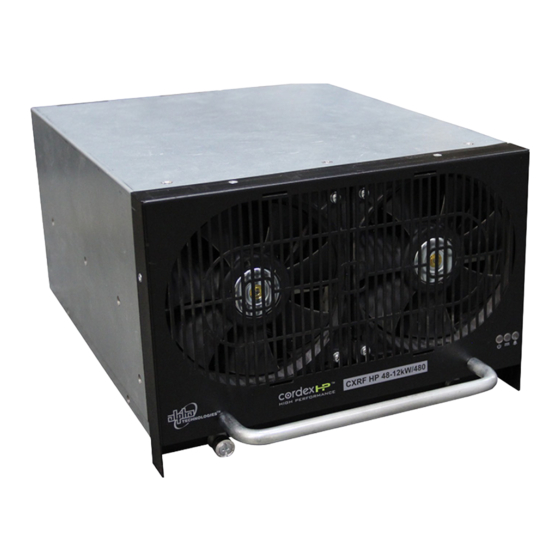
- Page 6 List of Figures Figure 1 — Cordex 48-12kW/480 ....................7 Figure 2 — Power Derating vs Ambient Temperature ..............11 Figure 3 — Power Derating vs Input Voltage ...................11 Figure 4 — 12kW Rectifier Front Panel LEDs ................12 Figure 5 — Cordex CXC HP Controller................... 16 Figure 6 —...
-
Page 7: Safety
If there are any questions regard- ing the safe installation or operation of this product, contact Alpha Technologies or the nearest Alpha representa- tive. Save this document for future reference. -
Page 8: Electrical Safety
1.4 Electrical Safety WARNING! Hazardous voltages are present at the input of power systems. The DC output from rec- tifiers and batteries, though not dangerous in voltage, has a high short-circuit current capacity that may cause severe burns and electrical arcing. •... -
Page 9: Introduction
The Cordex HP 48-12kW/480 is a perfect solution for various 48Vdc high capacity applications including Central Office, MTSOs and Data Centers. Cordex HP 48-12kW/480 is a true three-phase, three wire, 480 VAC input rectifier which meets the critical require- ments of current high density telecommunications environments. It combines the latest DSP controlled power conversion technology, to provide a flexible, efficient, and very highly reliable DC power source. -
Page 10: Part Numbers And List Options
2.3 Part Numbers and List Options The product, options, and accessories can be ordered by using the part numbers in the following table. Description List Option Cordex 48-12kW rectifier power module 0100020-001 5000064 Fan, spare for Cordex 48-12kW/480 7050308-001 MOV replacement assembly 0300167-XXX Cordex 48-12kW/480V, 3 phase 23"... -
Page 11: Specifications
3. Specifications Table A — 12kW Rectifier Specifications Electrical Input voltage (3ф-3W + PE): Nominal: 480Vac Operating: 375 to 530Vac Extended: 375 to 430Vac (de-rated power) Note: Neutral is not required at rectifier or shelf Maximum Input Voltage Phase Imbalance: Input Frequency: 47 to 63Hz Input Current:... - Page 12 Mechanical 160mm x 261mm x 326mm (6.25in x 10.3in x 11.8in) Dimensions H x W x D: 175mm x 261mm x 364mm (7in x 10.3in x 14.38in) including front panel and handle Weight: 12.8kg (28.2lbs) Environmental Temperature: Operation: -10 to 65°C (14 to 149°F); (see Figure 2 on page 11) Full Nominal Output Power: 0 to 40°C Storage:...
-
Page 13: Power Derating Vs Ambient Temperature
3.1 Power Derating vs Ambient Temperature For ongoing reliability of the rectifier, the output power is reduced when the ambient temperature is very high or very low, see Figure 2. Figure 2 — Power Derating vs Ambient Temperature 3.2 Power Derating vs Input Voltage The output power is reduced when the input voltage drops below 430Vac, see Figure 3. -
Page 14: Rectifier Features
4. Rectifier Features 4.1 Front Panel LEDs The front panel LEDs indicate: • Rectifier status summary • Rectifier software upgrade in progress • Patterned response to Locate Module command The rectifier status summary shows the rectifier alarm status, communication fail status, and rectifier on/off status. AC ON (1) The green LED is illuminated when the AC input voltage is within its allowable range. - Page 15 ALARM / FAULT (3) The red LED is illuminated when a major alarm is detected and the module is unable to source power because of any of the following conditions: AC Line Frequency High Output Fuse Open AC Line Frequency Low Output Over Current Protection (OCP) AC Line Over Current Protection Output Over Voltage Protection (OVP)
-
Page 16: Rectifier Rear Panel
4.2 Rectifier Rear Panel The 12kW rectifier has three connectors for shelf power and communications on the rear panel. These three con- nectors align with corresponding connectors in the shelf when the rectifier is installed. 4.3 True Module Fail Alarm The power modules have a “true”... -
Page 17: Current Limit/Short Circuit Protection
4.9 Current Limit/Short Circuit Protection The current limit function determines the maximum output current limit of the rectifier module, regardless of the output voltage or power. The maximum output current is limited to a constant value. Current limiting can be used to mate the rectifier output current ampacity to the needs of the load and parallel battery to minimize excessive battery recharge currents. -
Page 18: Cordex Hp Controller (Cxc Hp)
5. Cordex HP Controller (CXC HP) The Cordex™ HP (CXC HP) controller provides centralized setup, control and monitoring of power systems. This ranges from simple monitoring and threshold alarms for temperature, voltage and current, to advanced battery charging and diagnostic features. The controller supports dual Ethernet ports and a 4.3”... -
Page 19: External Peripherals
• USB: dual ports on both the front and rear of the controller for upgrades and file management via a standard USB flash drive. • CAN: dual independent CAN bus ports for communication with the Alpha Cordex™ and AMPS family of products, which allows for a greater number of devices. -
Page 20: Figure 8 - Shelf/Bay Id
Digital Inputs The L-ADIO can accommodate up to eight digital input channels, D1 – D8. Each channel responds to a zero or system voltage potential at the input to activate or deactivate the appropriate condition. These channels can monitor digital alarm/control signals from rectifiers, converters and many other types of equipment. An additional digital input, “EXT”... -
Page 21: Inspection
If any damage is observed contact the carrier immediately. Continue the inspection for any internal damage. In the unlikely event of internal damage, inform the carrier and contact Alpha Technologies for advice on the impact of any damage. -
Page 22: Installation
7. Installation The equipment is suitable for installation in Network Telecommunication Facilities. WARNING! This system is designed to be installed in a restricted access location that is inacces- sible to the general public. The following procedure is written for qualified personnel to install this product in a clean and dry environment. 7.1 Safety Precautions Refer to the Safety section near the front of this manual before beginning this installation. -
Page 23: Power System Assembly And Mounting
7.3 Power System Assembly and Mounting 7.3.1 Shelf Preparation/Mounting NOTE: Mount the shelf in a clean and dry environment. Allow at least 1.75" of free space in front of the unit for unrestricted cooling airflow. Sufficient free space must be provided at the front and rear of the power system. -
Page 24: Wiring
8. Wiring This chapter provides cabling details and notes on cable sizing for DC applications using the Cordex 48-12kW, modular switched mode rectifier systems. Refer to the Safety section on page 5 for safety precautions. WARNING! Ensure that the power at the AC service panel is switched off. Remove battery line fuses or connections before attempting work on the wiring. -
Page 25: Ac Input Connections
CAUTION! To minimize EMI disturbances, route the AC input wires in flexible or rigid conduit and located as far away as possible from the DC power wires. WARNING! Use care when removing or replacing the covers for the AC input connections. Never assume that an electrical connection or conductor is not energized. -
Page 26: Can Serial Ports (Rectifier Shelf)
8.5 CAN Serial Ports (Rectifier Shelf) Each module communicates with the CXC HP controller using CAN protocol. The modules report alarms, rectifier output voltages, and the location of the module within a cabinet. 8.5.1 Making CAN Bus Connections Figure 9 shows an example of a controller and three shelves. 1. -
Page 27: Shelf Id Connection
8.6 Shelf ID Connection The shelf/bay ID/ comes factory installed. If shelves are installed in more than one bay, then set the Bay ID sequentially on each Shelf ID board. Rack-mounted Shelf ID Example of a single bay with two rectifier shelves. Bay ID 1 (manually set) J2 J3 J4 J5 J6 J7 J8 J9... -
Page 28: Signal Wiring Connections To L-Adio Board
8.7 Signal Wiring Connections to L-ADIO Board For terminal block connections, the recommended wire sizes are 0.823 to 0.129mm (#18 to #26 AWG) for the temperature range of 0 to 50 deg. C (as per UL/CSA). CAUTION! To reduce risk of fire, use only 0.129 mm² (#26 AWG) or larger wire. 8.7.1 Relay Outputs Terminals provide contacts for extending various alarm or control signals. - Page 29 Voltage level definitions for digital inputs The digital input channels can be programmed for “active high” or “active low.” Active high indicates “alarm on the presence of a ground signal” and active low indicates “alarm on the removal of a ground signal.” See CXC HP Software manual for detailed instruction on programming.
-
Page 30: System Startup
9. System Startup Visually inspect the installation thoroughly. After completing the system installation and power system wiring, perform the following startup and test proce- dure to ensure proper operation: 9.1 Check System Connections 1. Make sure that the AC input power is switched off, the batteries are disconnected, and all the power modules are removed from the shelf. -
Page 31: Rectifier Modes
9.5 Rectifier Modes There are two main rectifier modes: output voltage mode and the output current/power mode. 9.5.1 Output Voltage Modes Voltage modes are under software control, and can be used to directly adjust the output voltage. The qualifica- tion of “under software control” is made because there are processes that occur in the rectifier that can change the output voltage that do not adjust the output voltage directly, for example, if the rectifier has reached the cur- rent limit. -
Page 32: Factory Ranges And Defaults
9.6 Factory Ranges and Defaults Table E shows the rectifier settings/ranges/defaults. Changes are made through the CXC HP interface Table E — Rectifier factory ranges and defaults Setting Range (minimum to maximum) Default Float (FL) Voltage 47.5 – 58.2V Equalize (EQ) Voltage 49.8 –... -
Page 33: Maintenance
10. Maintenance Although very little maintenance is required with Alpha systems, routine checks and adjustments are recom- mended to ensure optimum system performance. Qualified service personnel should do the repairs. The following table lists a few maintenance procedures for this system. These procedures should be performed at least once a year. -
Page 34: Replacing A Rectifier Module
10.3 Replacing a Rectifier Module NOTE: When a rectifier fails and or is permanently removed, the system generates a Rectifier Comms Lost alarm. The alarm is cleared by removing the rectifier from the system inventory. Replacing a Rectifier To remove the rectifier from the system inventory do the following: 1. -
Page 35: Fan Replacement
10.4 Fan Replacement WARNING! Do not work inside the rectifier module while it is energized. If working on the system with battery connected, use insulated tools to prevent accidental contact and arc flash A recommended replacement period of six years is suggested for preventative maintenance. 1. -
Page 36: Mov Replacement
10.5 MOV Replacement WARNING! Do not work inside the rectifier module while it is energized. If working on the system with battery connected, use insulated tools to prevent accidental contact and arc flash Lethal voltage persists inside the unit for several minutes after removal from the shelf. Allow 10 minutes before removing fan grill. - Page 37 6. Remove the five screws from the module. Carefully remove the old MOV board from the rectifier. 8. Place the new MOV board into location by inserting it through the bottom of the chassis and secure to module using five screws. Torque to 5in.Ib. 9.
-
Page 38: Acronyms And Definitions
11. Acronyms and Definitions Alternating current ANSI American National Standards Institute American Wire Gauge British thermal unit Controller area network Canadian Electrical Code Canadian Standards Association Cordex™ series; e.g., CXC for Cordex System Controller Direct current DHCP Dynamic Host Configuration Protocol Electronic Industries Alliance Electromagnetic compatibility Electromagnetic interference... -
Page 39: Warranty And Service Information
12. Warranty and Service Information Technical Support In Canada and the USA, call toll free 1-888-462-7487 Customers outside Canada and the USA, call +1-604-436-5547. Warranty Statement For full information details review Alpha's online Warranty Statement at http://www.alpha.ca/warranty. Limited Hardware Warranty Alpha warrants that for a period of two (2) years from the date of shipment its products shall be free from defects under normal authorized use consistent with the product specifications and Alpha’s instructions, unless otherwise specified in the product manual, in which case, the terms of the manual will take precedence... -
Page 40: Certification
13. Certification About CSA and NRTL CSA (Canadian Standards Association also known as CSA International) was established in 1919 as an independent testing laboratory in Canada. CSA received its recognition as an NRTL (Nationally Recognized Testing Laboratory) in 1992 from OSHA (Occupational Safety and Health Administration) in the United States of America (Docket No. - Page 46 Fax: +90 216 370 23 68 www.alphapower.mx www.alpha.com.tr Alpha Technologies Ltd. Due to continuing product development, Alpha Technologies reserves the right to change specifications without notice. 0100020-J0 (03/2019) Copyright © 2019 Alpha Technologies. All Rights Reserved. Alpha® is a registered trademark of Alpha Technologies.
Need help?
Do you have a question about the Cordex HP 48-12kW/480 and is the answer not in the manual?
Questions and answers