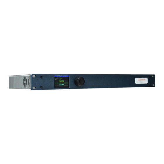
Summary of Contents for TSL TALLYMAN TM1-Mk2
- Page 1 Installa�on Manual TM1-Mk2 TM1-Tally TM1-Mk2+ TM1-Mk3+ Notes: Serial Number 68983 onward Issue 2...
- Page 2 Version History Issue Date Change Details 06/11/17 First Issue 11/12/23 Added TM1-Tally and TM1-Mk3+ Page 2 of 17...
-
Page 3: Table Of Contents
TM1-Mk2+ and TM1-Mk3+ Connections Pin-out details Default IP Initial setup TM1-Mk2+ and TM1-Mk3+ Connections Pin-out details Initial setup Safety Installation Earthing/Grounding Mounting Power Warranty, maintenance and repair Failure during warranty Technical support information TSL returns procedure Page 3 of 17... -
Page 4: Introduction
Introduc�on The following document covers installa�on of the TSL Tallyman controllers TM1-Mk, TM1-Tally, TM1-Mk2+ and TM1-Mk3+. All operational set-ups such as the router assignments, mnemonics and tally routing are programmed with a set-up computer running another the TallyMan configuration so�ware normally connected to the Ethernet Port on the TallyMan Controller. -
Page 5: Installation
Installation TM1-Mk2 and TM1-Tally The TallyMan controller should be installed in a standard 19” rack with good ventilation, no other special precautions need be taken, further informa�on regarding earthing, moun�ng, power etc may be found in Safety section. Connections GPIO 1-32 This is for the parallel tallies. -
Page 6: Pin-Out Details
Pin out details Ethernet The cable required to connect the TM1 controller with the configuring computer is as follows: Signal Name RJ-45 Ethernet Pin Crossover Cable Numbers Pinouts TX + TX - RX + EPWR + Power EPWR + Power RX - EPWR - Power EPWR - Power... - Page 7 GPIO GPIO INPUT/OUTPUT CONNECTORS D37 SOCKET TALLY 1 TALLY 20 TALLY 2 TALLY 21 TALLY 3 TALLY 22 TALLY 4 TALLY 23 TALLY 5 TALLY 24 TALLY 6 TALLY 25 TALLY 7 TALLY 26 TALLY 8 TALLY 27 TALLY 9 TALLY 28 TALLY 10 TALLY 29...
- Page 8 Parallel (GPI) tallies are connected directly to the GPIO 1-32 and GPIO 33-64 connectors on the TM1 controller. These are freely assignable as inputs or outputs. Tally inputs will occupy the lowest numbered pins star�ng with the Tally 1 connector. The output parallel tallies (if any are assigned) will start from the next available pin on the D37 connector.
-
Page 9: Default Ip
IP Address: 192.168.205.125 Subnet Mask: 255.255.255.0 Connection for configuration purposes is via a PC running TallyMan, available for download from the TSL website www.tslproducts.com Initial setup To setup the TM1-Mk2 and TM1-Tally press the encoder on the front panel once to display the current setup, press a second time to enter the IP settings and follow the on-screen instructions. -
Page 10: Connections
TM1-Mk2+ and TM1-Mk3+ The TallyMan controller should be installed in a standard 19” rack with good ventilation, no other special precautions need be taken, further informa�on regarding earthing, moun�ng, power etc may be found in Safety section. Connections GPIO 1-32 This is for the parallel tallies. -
Page 11: Pin-Out Details
Pin out details Ethernet The cable required to connect the TM1 controller with the configuring computer is as follows: Signal Name RJ-45 Ethernet Pin Crossover Cable Numbers Pinouts TX + TX - RX + EPWR + Power EPWR + Power RX - EPWR - Power EPWR - Power... - Page 12 GPIO GPIO INPUT/OUTPUT CONNECTORS D37 SOCKET TALLY 1 TALLY 20 TALLY 2 TALLY 21 TALLY 3 TALLY 22 TALLY 4 TALLY 23 TALLY 5 TALLY 24 TALLY 6 TALLY 25 TALLY 7 TALLY 26 TALLY 8 TALLY 27 TALLY 9 TALLY 28 TALLY 10 TALLY 29...
- Page 13 Parallel (GPI) tallies are connected directly to the GPIO 1-32 and GPIO 33-64 connectors on the TM1 controller. These are configurable as inputs or outputs in the TallyMan configuration so�ware. Tally inputs will occupy the lowest numbered pins star�ng with the Tally 1 connector. The output parallel tallies (if any are assigned) will start from the next available pin on the D37 connector.
- Page 14 Relay outputs The Relay Outputs consist of isolated relay contact pairs. Current loading is rated at 0.5A at 125 VAC, 1A at 24 VDC, non-inductive. RELAY OUTPUT CONNECTOR D37 SOCKET Relay 1a Relay 10b Relay 1b Relay 11a Relay 2a Relay 11b Relay 2b Relay 12a...
-
Page 15: Initial Setup
Initial setup Connection for configuration purposes is via a PC running TallyMan Configuration So�ware, available for download from the TSL website www.tslproducts.com Front Panel Setup TM1-XXX Menu Layout - Redundancy Mode To setup the TM1-MK2+ or TM1-Mk3+, press the encoder on the front panel once enter the menu (V3.XXX onward):... -
Page 16: Safety
Safety Installa�on Unless otherwise stated TSL equipment may be installed at any angle or position within an opera�ng temperature range of 5 ~ 25 degrees C. All TSL equipment conforms to the EC Low Voltage Direc�ve: EC Low Voltage Direc�ve (73/23/EEC) (OJ L76 26.3.73) (LVD). -
Page 17: Warranty, Maintenance And Repair
Warranty, Maintenance and Repair All TSL equipment is guaranteed for one year from the date of delivery to the customer’s premises. If the equipment is to be stored for a significant period, please contact TSL concerning a possible extended warranty period.


Need help?
Do you have a question about the TALLYMAN TM1-Mk2 and is the answer not in the manual?
Questions and answers