
Related Manuals for vissonic VIS-CATC-B


Summary of Contents for vissonic VIS-CATC-B
- Page 1 VIS-CATC-B Camera Auto tracking controller User Manual V2.3 VISSONIC ELECTRONICS LIMITE...
- Page 2 The meaning of symbols Safety instructions For your safe and correct use of equipment, we use a lot of symbols on the equipment and in the manuals, demonstrating the risk of body hurt or possible damage to property for the user or others.
- Page 3 Important note Warning In order to ensure the reliable performance of the equipment and the safety of the user, please observe the following matters during the process of installation, use and maintenance: The matters needing attention of installation Please do not use this product in the following places: the place of dust, soot and electric conductivity dust, corrosive gas, combustible gas;...
- Page 4 Please use the latest user manual. The copyright of the manual belongs to VISSONIC ELECTRONICS LIMITED. This manual is protected by the Copyright Law of the People's Republic of China and other intellectual property laws and regulations.
-
Page 5: Table Of Contents
Content 1. Overview ............................6 1.1.Function ..........................6 1.2.Main Specifications ......................6 1.3.VIS-CATC-B camera tracking seamless switching controller front and rear panel function description ............................6 1.4.Installation ........................... 7 1.4.1.19-inch installation cabinet ..................7 1.5.Connection .......................... 8 1.5.1.Power supply ......................8 1.5.2.RS-232 control interface .................. -
Page 6: Overview
Power interface: 1 AC power interface; Power supply: rated AC100 ~ 240V; Dimensions: 19-inch rack cabinet, height 1U, depth 260mm (without panel); Color spray: black; Weight: ≤ 3.5kg; Power consumption: ≤8W. 1.3. VIS-CATC-B camera tracking seamless switching controller front and rear panel function description... -
Page 7: Installation
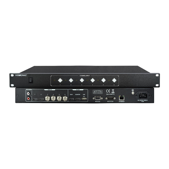
Figure 1.3 VIS-CATC-B the front and rear panels The front panel of camera tracking includes: Power switch - turn the power of the camera tracking controller on or off Control button - 1 - 6 button corresponds to 1 - 6 HDMI and SDI input channels, can switch any 1 HDMI or SDI input signal to HDMI output ... -
Page 8: Connection
Figure 1.4.1 1.5. Connection 1.5.1. Power supply Connect the main unit to an external power outlet using the supplied power cord. Figure 1.5.1 1.5.2. RS-232 control interface... - Page 9 Figure 1.5.2 RS232 female It is used to connect the digital network DSP conference main unit for video switching control of camera tracking or connect the computer for control. Signal Description Signal Description Null Null Send data Null Receive data...
- Page 10 <#Splice_mode[x]> Multiple image mode selection <Splice_mode[x]> [x]:0--11 <#Audio_chn[x]> Audio channel selection <Audio_chn[x]> Set the screen freeze time to x [x]:Unit: FREEZE[x]. FREEZE[x]. seconds second SetFreeze. Perform screen freeze <SPORT80> Query network parameters <^NET> <SIPR[X1].[X2].[X3].[X 4]> <GAR[X1].[X2].[X3].[X 4]> <SUBR[X1].[X2].[X3].[ X4 ]>...
-
Page 11: Network Control Protocol
1.6. Network control protocol Default IP: 192.168.10.189 Port: 80 Using TCP Connection Menu item Send parameter Return parameter Description {“version”:” X” } Version {param=version}- X:vierson number {“out1”:X1, “out2”:X2, “out3”:X3, “out4”:X4, Toggle Status {param=status} “audio”:X1,“mode”:X1 {“HDMI-1”:true/false, “HDMI-2”:true/false, “SDI-1”:true/false, Input Signal “SDI-2”: true/false,... - Page 12 Figure 1.7.1 PC network segment Log in to the web page, enter the IP address 192.168.10.189, and if you can log in to the interface as shown in Figure 6.2, it means that the connection is successful. Click Video and Audio to control the screen segmentation and audio switching of the camera tracking controller.
- Page 13 Figure 1.7.3 Audio switch ④ Audio switching - 1-channel analog audio and 6-channel digital audio input can be switched to output arbitrarily Network settings: as shown below: Figure 1.7.4 Network settings ⑤ IP Settings- Modify IP, gateway, subnet mask and MAC View version: as shown below: Figure 1.7.5 Version...
-
Page 14: System Connection Diagram
2. System connection diagram 2.1. Camera RS232 cascade control line connection method PIN1……DTR;PIN2……DSR;PIN3……TXD;PIN4……GND;PIN5……RXD;PIN6……GND ;P IN7……IROUT; PIN8……NC 2.2. Full Digital Network DSP Conference Controller CAMERA Menu--Camera Tracking Settings Enter the menu 'CAMERA' to set the parameters of the camera tracking. - Page 15 Protocol SAMSUNG, Select the protocol according to the PELCO-D, camera model, When the camera VISCA, tracking controller VIS-CATC-B is CUSTOM, used and the protocol needs to be set VCA-UDP to 'custom', the camera tracking is processed by VIS-CATC-B without setting the submenus' camera map...
- Page 16 Step 2: The upper control port of the conference processor CONTROL is connected with the RS232 port of the camera tracking controller VIS-CATC-B. Step 3: Use the front panel of the conference processor and the camera remote control, keyboard or CLEACON software to set the camera tracking preset position and input the camera information according to the following steps.
Need help?
Do you have a question about the VIS-CATC-B and is the answer not in the manual?
Questions and answers