
Summary of Contents for ENERGY SUPPORT CORPORATION DTF-102
- Page 1 Instruction Manual DTF-102 Receiver Type:DTF-102 No.-3243E R2 【Product】 ・ DTF-102 Receiver :KX-621038-XXXXXX...
- Page 3 Preface This manual is written for those who handle DTF-102 type receiver. Be sure to read this manual before using the product to ensure proper and safe operation of the product. In particular, be sure to read "For Your Safety" and use the product correctly. And keep it in a place where anyone using this product can view it at any time.
- Page 4 [Warranty Scope] The scope of warranty is limited to our products. Regardless of the warranty period, our company does not take any responsibility for the following. Indirect damage due to failure of our products or unforeseen defects by our company (Loss of profit, opportunity loss, compensation for damage or failure to products other than those supplied by us, compensation for other operations, compensation for accidents, etc.).
- Page 5 About This Instruction Manual Deliver this manual to the final user. The contents of this manual are subject to change without notice for improvement. Unauthorized reproduction or duplication of part or all of the contents of this manual is strictly prohibited.
- Page 6 For Your Safety Warning messages given here are for safe and correct use of the product and for prevention of harm or damage. These are important safety note, so be sure to read it carefully before use and be sure to observe it.
- Page 7 When deciding on the "Installation Location" Explosion or Fire This product is not explosion-proof. Do not use in an explosive gas atmosphere. DANGER When using a standard gas cylinder, install or store the standard gas cylinder in a location with an ambient temperature of 40°C or less and out of direct sunlight.
- Page 8 When "Starting measurement" or "Maintenance work" Fire, Electric shocks, Malfunction Be sure to turn OFF the main power supply before performing wiring connection work or wiring check. Before turning ON the power, make sure that the power wiring is properly connected.
- Page 9 Product Handling Information If this product is used in a manner not specified by us, it may impair the protective functions and performance provided by this product. It is strictly prohibited to modify the product by the customer. Observe the following precautions. General ...
- Page 10 VIII...
- Page 11 Table of Contents Type:DTF-102 Product Name:DTF-102 Receiver Table of Contents Preface ........................I For Your Safety ....................IV Product Handling Information................VII 1 Overview ......................5 1.1 About This Product ........................ 5 1.2 Products and Accessories ..................... 5 1.3 Temporary Storage ....................... 5 2 Part Names ......................
- Page 12 Table of Contents 5 Calibration ..................... 25 5.1 About Calibration ........................ 25 5.2 Calibration Point and Calibration Type ................25 5.2.1 Calibration Point Type ......................... 25 5.2.2 Calibration method Type ......................26 5.3 Manual Calibration ......................27 5.3.1 Manual Calibration (Air Point) ...................... 27 5.3.2 Manual Calibration (Air Point &...
- Page 13 Table of Contents 7.5 Other Functions ........................50 7.5.1 Concentration Upper / Lower Alarm (Alarm H, Alarm L, Alarm H&L) ..........50 7.5.2 Primary Delay Calculation Function ....................50 7.5.3 Moving Average Function ......................50 7.5.4 Protection Function of Set Value ....................50 7.6 CH Data Table ........................
- Page 14 Table of Contents 4...
- Page 15 1 Overview 1 Overview 1.1 About This Product This product is a control device that drives and controls the oxygen sensor in an oxygen analyzer that uses a limiting current type zirconia oxygen sensor, and is responsible for concentration calculation and output.
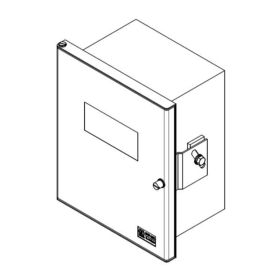
- Page 16 2 Part Names 2 Part Names 2.1 Receiver 【Dimensions】 Window Knurled fastener Right side view Front view Door Mounting hole Φ10 Bracket 1 Bracket 2 Wiring hole 7-Φ27 With grommets Bottom view *Dimensional tolerances without individual tolerance indications are according to JEM 1459.
- Page 17 2 Part Names 【Inside】 Display panel (For detail, see below fig.) Door Fuse Power switch Terminal block Display panel 【Display Panel】 Display 1 "Oxygen concentration", "Setting data", "Error code" and "Countdown" are displayed. Power lamp % lamp Lights when the power is on. Lights when the concentration unit is %.
- Page 18 Use instrument air or atmospheric gas for calibration. (Calibration using standard gas cylinders such as zero gas and span gas is not required.) DTF-102 Receiver TF-10 Probe Transmitter Check valve...
- Page 19 "receiver key operation", "contact input", and "receiver internal timer". Use instrument air or atmospheric gas for calibration. (Calibration using standard gas cylinders such as zero gas and span gas is not required.) DTF-102 Receiver TF-10 Probe Transmitter Check valve...
- Page 20 3 Installation 3.2 Place Conditions for Installation When deciding on the "Installation Location" Explosion or Fire This product is not explosion-proof. Do not use in an explosive gas atmosphere. DANGER When using a standard gas cylinder, install or store the standard gas cylinder in a location with an ambient temperature of 40°C or less and out of direct sunlight.
- Page 21 3 Installation 3.3 Installing the Receiver When "Installing" or "Transporting" Fall, Damage or Injury Installation work correctly according to the instruction manual. CAUTION Tighten screws with the appropriate tightening torque. Insufficient tightening may cause damage or drop. Also, if it is tightened too much, it may not be possible to remove it.
- Page 22 3 Installation 3.3.3 Stand Mount An optional stand mounting bracket is required to mount the receiver on a 50A pole. Attach Bracket 1 and Bracket 2 in the direction shown in Fig. 3-7. And attach to the pole with the Stand Mounting Brackets 1 and 2. 50A Pole Bracket 1 (3), (5), (6)
- Page 23 3 Installation 3.4 Connecting Wires When "Wiring" Fire, Electric shocks, Malfunction Wiring work should be done by a person with appropriate technical training and experience. Use the power supply at the rated voltage. Be sure to turn OFF the main power supply before performing wiring WARNING connection work or wiring check.
- Page 24 Circuit protector (Temperature:max.60℃) ・HCVV-S 2 sq×8 cores (Temperature:max.75℃) VS+ VSー IP+ IPー Hー Sー POWER POWER Power Grounding DTF-102 Receiver Analog Output Contact Input Contact Output OUT+ OUTー RY3 RY4A RY4A RY4B RY4B +24V +24V +24V S.V. S.V. DC 24 V...
- Page 25 Relocate the wiring to the corresponding terminal on the DTF-102 receiver Move the wiring to the terminals of the DTF-102 receiver that have the same items as the "contact input items in use" and "contact output items in use". 【DTF-101 Receiver】...
- Page 26 ・ If "Z" is used in the product number, check the contact input/output items in the delivery specifications. ・ If the same solenoid valve is driven using the contact output of "AIR" and "Purge" in the existing equipment, With the DTF-102 receiver, it is possible to aggregate into one contact output by using "AIR or PUREG".
- Page 27 【Wiring confirmation sheet 】 usage example 1 ◇Usage example conditions ・Product No. of existing receiver :KX-621034-A3D180 ・Wiring location of existing receiver :IN3、RY1、RY4、RY5 ・Product No. of DTF-102 receiver :KX-621038-ACFADC Existing Receiver (DTF-101) ■ Product number of receiver KX-621034 KX-621036 KX-621028 ■ Contact Input ■...
- Page 28 【Wiring confirmation sheet 】 usage example 2 ◇Usage example conditions ・Product No. of existing receiver :KX-621034-A3D1A2 ・Wiring location of existing receiver :IN3、IN5、RY1、RY2、RY4、RY5 ・Product No. of DTF-102 receiver :KX-621038-ACFAFC Existing Receiver (DTF-101) ■ Product number of receiver KX-621034 KX-621036 KX-621028 ■ Contact Input ■...
- Page 29 4 Measurements 4 Measurements When "Starting measurement" Fire, Electric shocks, Malfunction WARNING Before turning ON the power, make sure that the power wiring is properly connected. Note Be sure to check the safety precautions for the oxygen sensor (transmitter) to be used before starting to use it.
- Page 30 4 Measurements 4.2 Starting and Stopping Measurement Starting Measurement After turn the power supply ON, this analyzer goes through 3-minutes countdown (temperature rise) to enter measurement state. And display the oxygen concentration, output the analog output (4-20 mA). However, in order to make stable measurements, warm up the instrument sufficiently before using it.
- Page 31 4 Measurements 4.3 Key Operation The key operation is used to setting sensor parameters, calibration operations, recover from error conditions, and change other settings. This is a very important operation, so be sure to check it. Note Key operation may change the oxygen concentration output. Therefore, when using the oxygen concentration output for control purposes, release the control functions before operating the keys.
- Page 32 4 Measurements 4.3.2 Display Transition After the power is turned ON, the display of the receiver changes as shown in Figure 4-1, depending on the state change of the receiver and key operation. Power ON Switching Display Temp. Rising 3-minutes CH No.
- Page 33 4 Measurements 4.3.3 Display by Operating State Operating states such as Sleep mode, Calibrating, Purging, etc. are indicated by symbols on display 2. In any operating state, the display can be switched to "CH No. selection state" with the keys. Table 4-3 Display by Operating Sates Operating Contents...
- Page 34 4 Measurements 4.3.4 Data Settings Overview This product has various setting items assigned to each 3-digit CH number. To change or check the setting value, select the CH No. corresponding to the setting item, and change/check the setting value of that CH No. Refer ...
- Page 35 5 Calibration 5 Calibration 5.1 About Calibration In order to correctly measure oxygen concentration, perform gas calibration using the reference gas (hereinafter referred to as calibration) in following cases. When using analyzer for the first time. After replacing the oxygen sensor. ...
- Page 36 5 Calibration 5.2.2 Calibration method Type This product can be calibrated by the following three methods. When changing the calibration method, it is necessary to change the CH data setting. Normally, we set the calibration method according to the customer's usage at the time of shipment. Table 5-2 Calibration Method Type CH 270 Cal.
- Page 37 5 Calibration 5.3 Manual Calibration 5.3.1 Manual Calibration (Air Point) When performing Air-point calibration by Manual Calibration, set the table 5-3 in advance. After setting it once, it is necessary to reset only when the set value is changed. Table 5-3 CH Setting for Air-point Calibration by Manual Calibration CH No.
- Page 38 5 Calibration 5.3.2 Manual Calibration (Air Point & Other Points) When performing other points calibration by Manual Calibration, set the table 5-4 in advance. After setting it once, it is necessary to reset only when the set value is changed. Table 5-4 CH Setting for Air-point Calibration and Other Points Calibration by Manual Calibration CH No.
- Page 39 5 Calibration Air-point calibration, Zero-point calibration and Span-point calibration by Manual Calibration are performed in the following procedure. Set CH setting Set the calibration point to be calibrated in "CH No.276". Set the gas concentration of the calibration point to be calibrated to "CH No.120-123". Perform Air-point calibration Perform Air-point calibration in the same way "5.3.1 Manual Calibration (Air Point)".
- Page 40 5 Calibration 5.4 Semi Auto / Auto Calibration Semi-auto and Auto calibration require a piping system that drives the solenoid valve for calibration gas using the contact output of the receiver. Contact output Instrument air or atmospheric gas Flow Valve meter 5.4.1 Semi Auto / Auto Calibration (Air Point) - advance setting –...
- Page 41 5 Calibration 5.4.2 Semi Auto Calibration (Air-Point) - Key Operation or Contact Input - Air-point calibration by Semi Auto Calibration is performed in the following procedure. Set CH setting Indication during Air-point Calibration (using key on receiver) Set " Table 5-5 " Omit it When it has already been set.
- Page 42 5 Calibration 5.4.3 Auto Calibration (Air-point) Air-point calibration by Auto Calibration is performed in the following procedure. Set CH setting Set " Table 5-5 " Omit it When it has already been set. Reset calibration cycle Turn OFF the power switch of receiver and turn ON the power again. Or set "1"...
- Page 43 5 Calibration 5.4.4 Semi Auto/Auto Calibration (Air Point & Other Points) - advance setting - When performing other point calibration by Semi Auto Calibration or Auto Calibration, set the table 5-6 in advance. After setting it once, it is necessary to reset only when the set value is changed. Table 5-6 CH Setting for other point Calibration by Semi Auto Calibration or Auto Calibration CH No.
- Page 44 5 Calibration 5.4.5 Semi Auto Calibration (Air Point & Other Points) - Key Operation or Contact Input - Air-point calibration, Zero-point calibration and Span-point calibration by Semi Auto Calibration are performed in the following procedure. Set CH setting Set " Table 5-6 " Omit it When it has already been set Calibration start operation (Set "1"...
- Page 45 5 Calibration 5.4.6 Auto Calibration (Air Point & Other Points) Air-point & Zero-point calibration or Air-point & Span-point calibration by Auto Calibration are performed in the following procedure. Set CH setting Set " Table 5-6 " Omit it When it has already been set Reset calibration cycle Turn OFF the power switch of receiver and turn ON the power again.
- Page 46 6 Purging 6 Purging 6.1 About Purging Purging is the process of blowing compressed air to remove dust and other foreign matter (hereafter referred to as dust) that has entered or deposited in the measurement gas flow path around the oxygen sensor or inside the sampling probe.
- Page 47 6 Purging 6.3 Semi Auto Purge / Auto Purge 6.3.1 Semi Auto Purge / Auto Purge - advance setting - When performing purge by Semi Auto or Auto, set the table 6-2 in advance. After setting it once, it is necessary to reset only when the set value is changed. Table 6-2 CH Setting for Semi Auto Purge or Auto Purge CH No.
- Page 48 6 Purging 6.3.2 Semi Auto Purge - Key Operation or Contact Input - Semi Auto Purge is performed in the following procedure. Indication during purge Set CH setting (using key on receiver) Set "Table 6-2". Omit it When it has already been set. 2 8 1 Purge start operation Purge start...
- Page 49 6 Purging 6.3.3 Auto Purge Auto Purge is performed in the following procedure. Set CH setting Set " Table 6-2 " Omit it When it has already been set. Reset purge cycle Turn OFF the power switch of receiver and turn ON the power again. Or set "1"...
- Page 50 6 Purging 6.4 Reset of Cycle Timer and Countdown 6.4.1 Reset Method of Cycle Timer Resetting the Auto Calibration and Auto Purge cycle timer restarts the delay time count. Table 6-3 shows how to reset the cycle timer. Table 6-3 Reset Method of Cycle Timer Timer reset Detailed procedure Reset target...
- Page 51 6 Purging 6.4.2 Cycle Timer Countdown The time until the next Auto Calibration and Auto Purge indicate in "CH No.288" and "CH No.289". CH No. Contents Data Remarks Indicate the time until the next Auto Next Auto Calibration countdown XX-XX Calibration starts as "XX day - XX hour"...
- Page 52 7 Other Settings/Functions 7 Other Settings/Functions 7.1 Analog Output 7.1.1 Analog Output Specifications Output number :One :O Item concentration :DC 4 to 20 mA Output Isolated output Load resistance 550Ω or less 7.1.2 Setting, Checking and Switching of Output Range Two ranges (HIGH range and LOW range) can be used for the output range corresponding to 4 to 20 mA DC.
- Page 53 7 Other Settings/Functions 7.1.3 Output Hold Function This function holds the analog output at a constant value when the sample gas is not being measured, such as during Temp. Rising, Calibration, Purging, Error occurrence, or Sleep Mode. The output hold operation is set by "CH No.23" and "CH No.24". Alternatively, You can hold the analog output by key operation or contact input regardless of the receiver status using "CH No.
- Page 54 7 Other Settings/Functions 7.1.4 Simulated Output This is a function to output an arbitrary value for loop check of analog output. Set the output value to be output in "CH No.225". And switch the simulated output stop/output in "CH No.224". CH No.
- Page 55 7 Other Settings/Functions 7.2 Contact Output 7.2.1 Contact Outputs Specifications Output number : 4 points : No-voltage relay contact Output capacity AC 250 V 1A Resistance load DC 30 V 1A Resistance load : RY1,RY2,RY3,RY4A,RY4B Terminal 7.2.2 Contact Outputs Items and Setting For contact output, set the output item of each contact in "CH No.200 to 203", Also, set the operation of each contact "normally open: NO/normally closed: NC"...
- Page 56 7 Other Settings/Functions Table 7-2 Details of Contact Output Contents and Operation(for RY1 - RY3) Contact operation Selection number in CH 204 - 206 setting Item Contents (purpose) "CH 200 to Receiver state 202" 0:NO 1:NC No use ― ― OPEN CLOSE Outputs a contact according to...
- Page 57 7 Other Settings/Functions Table 7-3 Details of Contact Output Contents and Operation(for RY4A, RY4B) Selection Contact operation number in Item Contents (purpose) Receiver state RY4A RY4B "CH 203" Power OFF OPEN CLOSE Error Detects power failure and Temp. rising CLOSE OPEN (Analyzer error) error occurrence.
- Page 58 Be sure Input no-voltage contact. Connecting a contact with voltage may cause a malfunction. Do not use the input contact in parallel connection or series connection with other devices. (Figure 7-1) It may damage the receiver or other equipment. DTF-102 DTF-102 Other device...
- Page 59 7 Other Settings/Functions 7.4 Sleep Mode 7.4.1 About Sleep Mode Sleep mode is a function that protects the oxygen sensor and measurement gas flow path from exhaust gases by continuously supplying purge air while the oxygen sensor is not driven. There are cases that non-driving oxygen sensor, measurement gas flow path and transmitter are exposed to exhaust gas and residual gas in the furnace, when combustion equipment is stopped for a long period of time due to installation, test, inspection or repair.
- Page 60 7 Other Settings/Functions 7.5 Other Functions 7.5.1 Concentration Upper / Lower Alarm (Alarm H, Alarm L, Alarm H&L) This function judges whether the measured value is "higher than the set value" or "lower than the set value" and outputs an alarm or contacts. When using this function, set "CH No.220 to 223".
- Page 61 7 Other Settings/Functions 7.6 CH Data Table Table 7-5 CH Data Table(1/3) CH No. Contents Setting range e.g. Default Remarks 0:----- Normal display setting 1:Oxygen concentration ― Sensor Vs monitor [mV] ― Sensor Ip1 monitor [mA] ― Sensor Ip2 monitor [µA] Monitor ―...
- Page 62 7 Other Settings/Functions Table 7-6 CH Data Table(2/3) CH No. Contents Setting range・Remarks e.g. Default Remarks 0:Heater OFF 1:Constant voltage control TF-10:3 *, ◇ Heater control mode 2:Constant resistance control 1 TF-Ⅲ:2 3:Constant resistance control 2 Heater voltage setting [V] 5.00 to 11.00 10.50 See inspection...
- Page 63 7 Other Settings/Functions Table 7-7 CH Data Table(3/3) CH No. Contents Setting range・Remarks e.g. Default Remarks 0:Manual Calibration * Calibration method type 1:Semi Auto Calibration 2:Auto Calibration Air-point gas sending time [min] 1 to 99 Zero-point and Span-point gas sending time [min] 1 to 99 Recovery-time [min] 1 to 99...
- Page 64 8 Maintenance 8 Maintenance The following maintenance and inspection procedures are important in order to maintain normal functioning and accurate measurement. Make sure you thoroughly understand the procedure before performing maintenance. When "Maintenance work" Fire, Electric shocks, Malfunction Be sure to turn OFF the main power supply before performing wiring connection work or wiring check.
- Page 65 9 Troubleshooting 9 Troubleshooting 9.1 Phenomena and Countermeasures Table 9-1 Phenomena and Countermeasures Phenomena Cause Countermeasures CH No.310 is entered with something other Set "102" in CH No.310. Unable to than "102" change data. Receiver problem Replace the receiver or repair by Maker. Reconfirm receiver status and settings.
- Page 66 9 Troubleshooting 9.2 Error Code Table Table 9-2 Error Code Error Code Contents Cause Countermeasures - Receiver abnormality E-01 Abnormality in ROM, RAM, Turn OFF power supply and turn ON after E-02 - Temporary malfunction due to 10 seconds. and/or EEPROM E-03 external noise E-04...
- Page 67 9 Troubleshooting 9.2.1 Oxygen Sensor Failed If "E-05" or "E-07" occurs during using (after a normal measurement period), the oxygen sensor may have failed due to its life. Follow the steps below to check the cause and restore the analyzer. "E-05"...
- Page 68 10 Technical Data 10 Technical Data 10.1 Specifications 1. Power supply AC 100 to 240 V±10% 50/60 Hz max.50 VA 2. External dimensions 300×250×156 [mm] 3. Weight Approx. 6.5 kg 4. Measurement item 5. Measurement range 0 to 25vol.% ±1.0 % F.S. ( F.S. = 0 to 25vol.% ) 6.
- Page 69 10 Technical Data MEMO...
- Page 70 The contents of this manual are subject to change without notice for improvement. For inquiries regarding product handling, please contact us or our distributors. Inquiry form URL:https://www.energys.co.jp/english/inq/all.php ENERGY SUPPORT CORPORATION 1, Aza Kamikobarii, Inuyama, Aichi 484-8505 Japan...
Need help?
Do you have a question about the DTF-102 and is the answer not in the manual?
Questions and answers