Table of Contents
Advertisement
Quick Links
Advertisement
Table of Contents

Subscribe to Our Youtube Channel
Summary of Contents for Scully Groundhog ST-47C Series
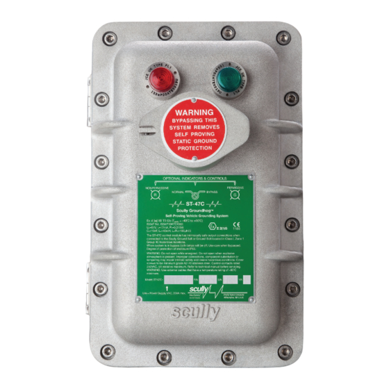
- Page 1 Scully ST-47C Groundhog Technical Manual ST-47C Series Self-Proving Vehicle Earthing Verification System Scully Signal Company / MaxSafety ® Tel. 617 692 8600 Fax. 617 692 8620 800 2 SCULLY (272 8559) SYSTEMS 70 Industrial Way, Wilmington, MA 01887-3479, USA sales@scully.com www.scully.com...
-
Page 3: Table Of Contents
ST-47C Groundhog - Technical Manual Table of Contents General Description Technical Specifications Accessory Equipment Installation Mechanical Installation Electrical Installation Initial System Checkout Maintenance Enclosure Corrosion Protection Control Module (Circuit Board) Module Replacement Indicator Lights Control (Bypass) Switch Junction Box and Plug & Cable Unit Troubleshooting Diagram Appendix DWG 31412 –... -
Page 4: Description
When wired into an overfill prevention system, the ST-47C Groundhog utilizes a spare conductor in the existing Scully overfill prevention plug and cable together with a special Scully Ground Bolt mounted on each vehicle. The Scully Ground Bolt sensing lead is wired to the Scully overfill prevention socket. - Page 5 Self-Proving Vehicle Earthing Verification System General 1.1.1 Model Designations The ST-47C Controller is available in 120VAC or 240VAC models, with or without control (Bypass) Switch. Model suffix (E) = Explosion-proof Enclosure, (L) = Indicator Lights, (K) = Key Lockable Bypass Switch.
-
Page 6: Technical Specifications
*20VA does not include circuits controlled by the output relay contact Vehicle Interface Scully Ground Ball (via Ground Ball connector plug), Scully Ground Bolt (via plug for overfill prevention socket), Clamp connection (Resistive). Output Relay One normally open volt-free contact rated 250VAC, 5A resistive max. -
Page 7: Accessory Equipment
Such use does not use a Ground Bolt or Ground Ball and, as such, does not have the anti-cheating advantages provided by the Ground Bolt or Ground Ball systems. Contact Scully Technical Services for more information. For a list of cables that integrate the ST-47C into Overfill Prevention systems, consult Scully Tech Data Sheet 60614. Page 7. -
Page 8: Installation
ST-47C Groundhog - Technical Manual Installation The ST-47C control system is typically installed in areas that are classified as hazardous locations due to nature of the products being loaded. Installation of the control unit and accessories must therefore be done by qualified personnel in accordance with all national and local regulations (codes) governing the installation of electrical equipment in hazardous locations. - Page 9 There are three holes in the enclosure for cable entry. Two holes in the top of the enclosure are for mains power and control output wiring. One hole in the bottom of the enclosure, labeled "Intrinsi cally Safe Entry" is for connection to ground verifications, via a Scully Sculcon Junction Box.
-
Page 10: Initial System Checkout
ST-2-DSWJ Tester has multiple socket configurations for connection to all Scully Sculcon Plug Models. Note: If the ST-47 is not being used integrally with a Scully overfill prevention system, you must provide a vehicle or simulation equipped with the ground verification device(s) installed. - Page 11 Self-Proving Vehicle Earthing Verification System Installation On units equipped with Bypass Control Switch: Return the Bypass Switch to the NORMAL position. The Bypass Switch should be kept under a lock (user provided) so that its setting cannot be tampered with. Connect the Sculcon plug to the socket on the tester.
-
Page 12: Maintenance
(See Figure 1 ST-47C Control Module Illustration on following page). Non-operational control modules may be returned to Scully for repair. Contact Scully Technical Services for assistance in obtaining a Return Material Authorization (RMA) before returning any material to the factory. - Page 13 Figure 1: ST-47C Control Module Illustration Note: The ST-47C Replacement Control Module cannot be repaired in the field. A damaged or faulty module must be replaced with an equivalent Scully ST-47C Control Module. The ST-47C Replacement Control Module must only be installed in Scully's explosion-proof enclosure.
-
Page 14: Indicator Lights
To protect it from loading arm damage etc., it is important to store the plug and cable out of harms way when it is not in use. A hook is provided on Sculcon Junction Box or, if an overfill prevention plug is used, a Scully Storage Socket may be used. Troubleshooting The following troubleshooting guide should aid in an initial diagnosis of most problems encountered with installation and operation of ST-47C. - Page 15 Self-Proving Vehicle Earthing Verification System Maintenance Condition Possible Cause • No lights ON, on front cover No power to control unit • Control (Bypass) Switch in OFF position • Bulb blown (on older units with incandescent lamps) • Input power fuse (F1) is blown •...
-
Page 16: Diagram Appendix
(50.8) 6.62 (168.1) SEE NOTE 2 TOP VIEW 10°, 4 PL 5.75 (146.0) 13.69 (MOUNTING LUG CENTERS) (347.7) scully (12.7) 6.75 8.44 (171.5) (214.3) (MOUNTING LUG CENTERS) FRONT VIEW REAR VIEW NOTES: 1. DIMENSIONS ARE IN INCHES WITH MILLIMETERS 8.38 IN PARENTHIESS. -
Page 17: Dwg 63039 - Outline Drawing - Sculcon Junction Box
Self-Proving Vehicle Earthing Verification System Diagram Appendix DWG 63039 – Outline Drawing – Sculcon Junction Box Page 17. -
Page 18: Dwg 61441 - Wiring Diagram - Typical Loading Rack Control
ST-47C Groundhog - Technical Manual Diagram Appendix DWG 61441 – Wiring Diagram – Typical Loading Rack Control Page 18. -
Page 19: Dwg 61442 - Mounting Diagram - Control Unit & Junction Box
Self-Proving Vehicle Earthing Verification System Diagram Appendix DWG 61442 – Mounting Diagram – Control Unit & Junction Box Page 19. -
Page 20: Dwg 61408 - Internal Wiring Diagram - St-47C-El
ST-47C Groundhog - Technical Manual Diagram Appendix DWG 61408 – Internal Wiring Diagram - ST-47C-EL Page 20. -
Page 21: Dwg 61407 - Internal Wiring Diagram - St-47C-Elk
Self-Proving Vehicle Earthing Verification System Diagram Appendix DWG 61407 – Internal Wiring Diagram - ST-47C-ELK Page 21. -
Page 22: Dwg 61404 - Installation Wiring Diagram, St-47C W/ Sc-47 Plug
ST-47C Groundhog - Technical Manual Diagram Appendix DWG 61404 – Installation Wiring Diagram, ST-47C w/ SC-47 Plug Page 22. -
Page 23: Dwg 61200 - Installation Wiring Diagram, St-47C W/ Sc-47 Clamp
Self-Proving Vehicle Earthing Verification System Diagram Appendix DWG 61200 – Installation Wiring Diagram, ST-47C w/ SC-47 Clamp Page 23. -
Page 24: Dwg 61405 - Installation Wiring Diagram, St-15C/St-47C
ST-47C Groundhog - Technical Manual Diagram Appendix DWG 61405 – Installation Wiring Diagram, ST-15C/ST-47C Page 24. -
Page 25: Dwg 61406 - Installation Wiring Diagram, St-35C/St-47C
Self-Proving Vehicle Earthing Verification System Diagram Appendix 4.10 DWG 61406 – Installation Wiring Diagram, ST-35C/ST-47C Page 25. -
Page 26: Dwg 61557 - Replacement Parts St-47C-120
Item 5, 6: LED style lamps used on models built after 10/04/01. * Replacement bulb for incandescent style explosion-proof lights only. Use on models built prior to 10/04/01. 61557, Rev B 2013 Scully Signal Company Scully Systems Europe NV Scully UK Ltd MaxSafety ® 70 Industrial Way,... -
Page 27: Dwg 61274 - Replacement Parts St-47C-240
Item 5, 6: LED style lights used on models built after 8/01 * Replacement bulb for incandescent style explosion-proof lights only. Use on models built prior to 8/01. 61274, Rev D 2013 Scully Signal Company Scully Systems Europe NV Scully UK Ltd MaxSafety ® 70 Industrial Way,... - Page 28 Notes: Page 28.
- Page 29 Notes: Page 29.
- Page 30 Notes: Page 30.
- Page 32 Scully is ISO certified and all of our products are 100% made in the U.S.A. In addition, we back up our products with the best service in the industry.
Need help?
Do you have a question about the Groundhog ST-47C Series and is the answer not in the manual?
Questions and answers