
Related Manuals for AC Air Technology T1H2


Summary of Contents for AC Air Technology T1H2
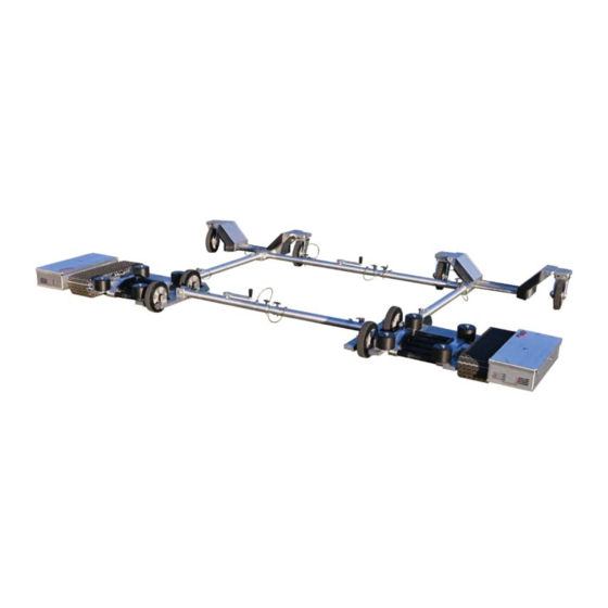
- Page 1 MODEL: T1H2 Helicopter Tug Instruction Manual 95631 Rev. c World’s First Portable, Remote-Control Aircraft Tugs...
-
Page 2: Table Of Contents
4-1. Radio Operation ..............27 4-2. Operating the Tug ..............28 4-3. Adjusting the Width of the T1H2 Tug ........30 4-4. Loading the T1H2 Under the Helicopter Skids ..... 31 4-5. Moving the helicopter with the T1H2 tug ......37 4-6. -
Page 3: Components
1. Components 1-1. Components in the Box (1) Right Main Tug Assm. 09612 Left Main Tug Assm. 09994... -
Page 4: Components In The Box (2)
1-2. Components in the Box (2) Short Front-end Adjuster Left End Assembly Assm. #09621 Assm. #09889 Long Back-end Adjuster Right End Assembly Assm. #09622 Assm. #09993 (2X) Frame Side Support Part #02617... -
Page 5: Components In The Box (3)
1-3. Components in the Box (3) Air Bag Hand Pump and Hose Part #95623 Assm. #02532 Auxiliary Wheels Lifter Pole Assm. #02532 Assm. #02533... -
Page 6: Components In The Box (4)
Part #02629 Part #95102 Part #95087 (2X) Tug Charger Owners Manual (2X) Spare Parts Bag Part #95394 Part #95631 Part #95631 (4X) T-Handle (4X) T1H2 Frame Insert (12X) Socket Head (2X) Shoulder Bolt Part #95545 Part #24244 Part #95304 Part #95655... -
Page 7: Tug Components (1)
1-5. Tug Components (1) Main Plate Track Assembly Skid Guide Rollers Skid Loading Rollers Power Switch Tug Charger Connection Side to Side Swivel Connection Right Back-end Connection Slot *Note Left Main Tug is an Identical Mirrored Component... -
Page 8: Tug Components (2)
1-6. Tug Components (2) Right Back-End Side to Side Insert Left Main Tug Swivel Connection Right Back-End Connection Slot Right Main Tug Swivel Connection Left Back-End Insert Right Back-End Connection Slot Left Back-End Insert Hole Right Back-End Insert... -
Page 9: Radio Components
1-7. Radio Components Radio Controller Power Indicator Control Stick 3 Speed Toggle Light Switch (Optional) Roller Engagement Switch Charging Indicator LED ON/OFF Switch Charging Jack Lanyard Anchor Warning: The control stick on the remote is very sensitive and will cause the tug to move if it is moved accidentally. -
Page 10: Charger Components
1-8. Charger Components Tug Charger (2 Included) Tug Connection Charging Indicator 110 V Power Connection Radio Charger 110 V Power Connection Radio Connection... -
Page 11: Spare Parts Kit
1-9. Spare Parts Kit • Spare Track Parts Rotoclips Treads Pins Links • Track Install Tools • Spare Track Parts 4 Amp Replacement Light Fuse Track Pin Tools 4 Amp Replacement Light Fuse Retainer Clip Tool... -
Page 12: Spare Parts: Track Tools
1-10. Spare Parts: Track Tools The Track Tools are used to assist in the installation of new tracks. This section is intended to show how the tools are used only. A detailed instruction guide is provided when purchasing new tracks. Refer to that instruction guide when installing new tracks. - Page 13 The Track Pin Tools are used to assist in the installation of new tracks Insert the Track Pin Tools on the inside and outside adjacent pins to the missing pin hole. Note: You will need to hold these in place by hand.
-
Page 14: Quick Guide
2. Quick Guide 2-1. Air Bag Infl ate the Air Bag to 50-60% capacity Hand Pump Air Bag Hose Place the Air Bag centered underneath As the tug approaches the helicopter’s the tail of the helicopter as shown center of gravity the tail will pivot down and rest on the air bag, protecting the tail from hitting the ground... -
Page 15: Auxiliary Wheels And Lifter Pole
2-2. Aux. Wheels and Lifter Pole If one track loses power, the auxiliary At one end of the track, position the Lifer wheels can be installed to temporarily Pole underneath the tug main plate. get the failed track off the ground and the helicopter off... -
Page 16: Tug Assembly
3-1 Front End Assembly Right Tug T-Handle Pin Adj. Handle (2X) 3/8”-16 Shoulder Blot Center Tube T1H2 Short Adjuster Right End T1H2 Short Adjuster Left End Center Numbered Tube Insert Measured Helicopter Skid Center to Center Distance End Numbered Tube Insert Left Tug... - Page 17 1. Slide the smaller diameter end of the Helicopter Frame Insert (Part #24244) into swivel con- nection shown above. Align the non threaded thru holes and while holding the insert in place screw in Shoulder Bolt (Part #95655). 2. Insert larger diameter end of Helicopter Frame Insert (Part #24244) into the end of the tube of assembly #09621.
- Page 18 This connection does not adjust and will re- main intact when adjusting the width of the T1H2 tug. Facing down on the adjustment handle turn it counter-clockwise until it can no longer turn.
- Page 19 5. Slide the smaller diameter end of the end numbered tube insert into the swivel connection shown above. Align the non threaded thru holes and while holding the insert in place screw in Shoulder Bolt (Part #95655). 6. With both tugs placed 5 inches less than the width measured, assuming it is possible and not at its minimum width, power one of the tugs on to aid in aligning the tubes.
- Page 20 7. Both the right and left tugs are now connected together. Take note of the numbers the T- Handle Pins have been inserted to after adjustment is complete as shown in the fi gure below. These numbers will aide with the back end assembly width adjustment in the fi nal step. Mid Section Tube Number End Tube Number Measured Helicopter Skid Center to Center Distance...
- Page 21 8. Insert (2x) T1H2 Frame Insert into the separate Heli Rail Support blocks attached individu- ally to each tug. Align the two threaded holes on each of the T1H2 Frame Inserts with the thru holes on the Heli Rail Support blocks. Using a 3/16” allen wrench screw in and fi rmly tightened (4X) socket head screws, two per side.
-
Page 22: Back End Assembly
3-2 Back End Assembly Right Back-End Tug Part # 09993 T1H2 Long Adjuster Part # 09622 (8X) 1/4”-20 Socket Head Part # 95304 Left Back-End Tug Part #09889 (2X) T1H2 Frame Insert Part #24244 T1H2 Roller Block Long Support Back-End Fully Assembled... - Page 23 Align the two threaded holes on each of the T1H2 Frame Inserts with the thru holes on the T1H2 Roller Block Long Supports. Using a 3/16” allen wrench screw in and fi rmly tightened (4X) socket head screws, two per side. Insert Fixed Long Frame Insert into the T1H2 Roller Block Long Support on the right side back-end assembly.
- Page 24 This connection does not adjust and will remain intact when adjusting the width of the T1H2 tug. Facing down on the adjustment handle turn it counter-clockwise until it can no longer turn.
- Page 25 End T1H2 Short Adjuster Mid-Section 5. Insert the T1H2 Long Adjuster End Numbered tube into T1H2 Roller Long Block and align the two threaded holes with the thru holes on the Left Back-end assembly. Screw in (2X) 1/4”-20 Socket Head to secure the Long Adjuster assembly to the Left Back-end Assembly.
- Page 26 Fully Assemble T1H2 Tug *NOTE* T1H2 TUG WILL VARY IN WIDTH DEPENDING ON THE HELICOPTER IT IS UTILIZED TO MOVE. FIRST TIME LOAD- ING SHOULD BE CAREFULLY OBSERVED BY OPERATOR TO ENSURE THE T1H2 HAS BEEN ADJUSTED TO THE PROPER WIDTH OF THE HELICOPTER SKIDS...
-
Page 27: Tug Operation
4. Tug Operation 4-1. Radio Operation 1. Switch the radio on and make sure the power indicator light turns on and the radio beeps once. If this does not happen, check to make sure the batteries were installed correctly. When the battery level in the radio becomes low the radio will begin to beep, signaling you to replace or recharge the batteries. -
Page 28: Operating The Tug
4-2. Operating the Tug Before turning on the tugs, make sure the tracks and bottom of the tugs are free from obstruction. Turn the tugs on using the ON/OFF switch. There will be a short series of beeps and then the ON/OFF switch will illuminate red to show the tug is on. - Page 29 4. After lifting the tugs off of the ground for any reason or taking it in and out of your trans- portation vehicle, you must check to make sure that the sprockets are correctly seated on the tracks. If the sprocket is not properly seated it could result in damage to the track.
-
Page 30: Adjusting The Width Of The T1H2 Tug
4-3. Adjusting the Width of the T1H2 Tug 1. Use the front and back cranks to adjust the width between the right side and left side tugs. Use the numbers on the extension tubes as reference for getting the front and back connecting tubes set at equal lengths. -
Page 31: Loading The T1H2 Under The Helicopter Skids
4-4. Loading the T1H2 Under the Helicopter Skids 1. Identify the center of gravity (CG) and mark or be able to readily identify its location as shown in the picture Fig. 3-1. NOTE: The center of gravity (CG) will vary depending on the model of helicopter 2. - Page 32 3. Align and center the skids onto the T1H2 rollers as shown below Forward Backwards Center Skid Centered onto cradle Skid Centered onto cradle Top View Skid Centered on tug...
- Page 33 4. Ensure the position on your transmitter is set to engage mode. Slowly move the tug forward and backwards until you visually confi rm the rollers on the cradle are fully en- gaged and are turning when the tug moves. Approach the skids slowly and align your tug so the skids on your helicopter are centered onto the rollers as pictured below.
- Page 34 5. Slowly drive the tug forward under the skids. As you drive under the skids the front of the helicopter will raise up and the tail will lower down. Verify the air bag is positioned under the tail properly to prevent the tail from hitting the ground. Then proceed with loading. 6.
- Page 35 7. When Loading the helicopter ensure the CG stays between the two points indicated below. If the CG passes the furthest from the loading side point indicated below immedi- ately stop and reverse direction until it is back at the safe CG point or before. NOTE: The center of gravity (CG) will vary depending on the model of helicopter being tugged.
- Page 36 8. Once the helicopter skids are completely loaded in the proper location on the tug then switch the Roller Engage Switch to the Lock position (the down position). Then move the tug very slowly backwards and verify the rollers on both sides of the tug are not turning. If either one of them is turning then reverse the movement of the tug forward moving very slowly and verify the rollers are not turning.
-
Page 37: Moving The Helicopter With The T1H2 Tug
4-5. Moving the helicopter with the T1H2 tug Use the joystick on the remote control to move the helicopter. Below are several notes to be aware of while you are moving the helicopter. 1. Carefully watch the position of the tail and rotors of the helicopter while moving. -
Page 38: Unloading The Helicopter From The T1H2 Tug
4-6. Unloading the helicopter from the T1H2 tug 1. Put the optional air bag under the tail or position a person at the tail to ensure it doesn’t drop too low and hit the ground. 2. When you are ready to unload the helicopter just move the “Engage/Lock” switch from the “Lock”... -
Page 39: Tug Care
5. Tug Care 5-1. Adjusting the Track Tension Track tension might need to be adjusted after several hours of use. Follow the instructions below for each track. 1. Remove 6 track cover screws from each tug and remove the outside track covers. Outside Track Covers Track Cover Screws Right Tug... - Page 40 3. Next place a screwdriver in the track adjustment prying slot shown on the previous page For the Right side tug track (shown) pry by pushing the screwdriver towards the front (loading side). For the Left side tug track pry by pushing the screwdriver towards the back (non-loading side).
-
Page 41: Charging The Tug
5-2. Charging the Tug 1. Before charging your tug, the radio and tug should both be turned OFF. Power Switch Tug Charging Jacks 2. Plug charger into charging jack and into a wall socket. The plug can only be inserted in one direction. 3. -
Page 42: Charging The Transmitter
5-3. Charging the Transmitter WARNING: Only use the supplied charger to charge the transmitter when using the supplied batteries or the following: - 1200mAh to 2200 mAh Ni-MH or Ni-Cd ‘AA’ Rechargeable Batteries The use of the transmitter charger with alkaline batteries installed can damage the transmitter. -
Page 43: Replacing Radio Batteries
5-4. Replacing Radio Batteries 1. Before changing the radio transmitter batteries, be sure the radio transmitter and tug are both turned OFF. 2. Remove the 2 screws on the back cover of the radio transmitter then remove the back cover. Note: Do not remove the front cover (with etched logo). - Page 44 4A. Replace the batteries by purchasing a new shrink wrapped Note: A shrink wrapped battery pack can battery pack from AC Air Technology be purchused from AC Air Techology to or installing the supplied battery tray replace the installed battery tray. To use a and purchasing 6 rechargable ‘AA’...
-
Page 45: Troubleshooting
6. Troubleshooting For technical support call or e-mail AC Air Technology (855) 884-7222 info@acairtechnology.com WARNING: DO NOT SIT IN THE HELICOPTER WHILE OPERATING THE TUG. TO PREVENT GOING BEYOND THE WIDTH LIMITS OF YOUR HELICOPTER SKIDS ENSURE TO MEASURE THE WIDTH ACCURATELY. BELOW ARE A FEW WAYS TO DO SO BUT ULTIMATELY IT IS AT THE OPERATORS DISCRETION AND LIABILITY TO PROPERLY LOAD THE HELICOPTER. - Page 46 Symptom Cause Action Detail Tug is ON No action required Tug will beep when initially turned on Tug charger indicator light will illuminate red when charging and green when fully charged. Battery voltage is getting Charge tug battery Tug will beep when the battery voltage is below Tug beeps 3 28 volts (power button flashing red).
- Page 47 “Details” tug to overstress. If the issue persists, call or section. email AC Air Technology tech support for further assistance. Remote controller and Rebind remote controller Call or email tech support for further assistance receiver are not binding and receiver.
- Page 48 Remote Controller Symptom Cause Action Detail See owner’s manual section “Replacing Charge remote controller Remote Transmitter Batteries” for details controller is Battery is low replace remote controller beeping It is recommended to keep the tug and remote batteries controller charging when not in use See owner’s manual section “Replacing Remote Charge remote controller...
-
Page 49: Warranty
In no event shall the liability of AC Air Technology exceed the individual price of the product on which liability is asserted. AC Air Technology has no control of the set up, ap- plication, use, modifi cation, or misuse of this product, thus no liability shall be assumed or ac- cepted for any resulting damage or injury.
Need help?
Do you have a question about the T1H2 and is the answer not in the manual?
Questions and answers