Table of Contents
Advertisement
Quick Links
Installation Instructions and User Manual
Si-750 , Si-750-PST ( 750 VA)
Si-950, Si-950-PST ( 950 VA)
Si-1150, Si-1150-PST ( 1150 VA)
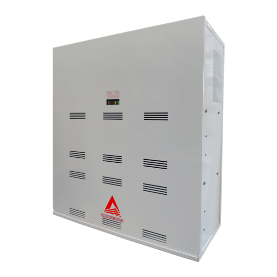
Pure Sine Wave Emergency Lighting Inverters
Si-
(includes - SDT Self Test/ Diagnostic and
CB Output Circuit Breaker models)
I Assurance Emergency Lighting, a division of Assurance Engineering LLC 357 Cumberland Street, Memphis, TN 38112 PH: 877-774-4775
Advertisement
Table of Contents

Related Manuals for Assurance Emergency Lighting Si-750

Summary of Contents for Assurance Emergency Lighting Si-750
- Page 1 Si-1150, Si-1150-PST ( 1150 VA) Pure Sine Wave Emergency Lighting Inverters (includes - SDT Self Test/ Diagnostic and CB Output Circuit Breaker models) I Assurance Emergency Lighting, a division of Assurance Engineering LLC 357 Cumberland Street, Memphis, TN 38112 PH: 877-774-4775...
- Page 2 READ AND FOLLOW ALL SAFETY INSTRUCTIONS IMPORTANT SAFEGUARDS When using electrical equipment, basic safety precautions should always be followed, includ- ing the following: READ AND FOLLOW ALL SAFETY INSTRUCTIONS: • Do not use outdoors. • Do not let power supply cords touch hot surfaces. •...
-
Page 3: Table Of Contents
Table of Contents Description Page Section 100 System Installation Instructions 101. Specifications....................... 4 102. Receiving, Moving and Storing Systems and Batteries ........5 102.1 Shipping Damage ....................5 102.2 Temporary Storage of Units and Batteries ............5 103. Installation Requirements ..................5 103.1 Operating Environment .................. -
Page 4: Section 100
• Operating temperature: 20ºC to 30ºC (68ºF to 86ºF) • Relative humidity: 95% non-condensing Note: Lead Calcium battery performance rated at 25°C (77°F) for load. Table 1 (Electrical & Physical Specifications) * System weights shown include installed batteries Si-750 Si-950 Si-1150... -
Page 5: 102. Receiving, Moving And Storing Systems And Batteries
102. Receiving, Moving and Storing Systems and Batteries 102.1 Shipping Damage Inverter system batteries are shipped separately. Carefully inspect all cartons upon receipt for evidence of shipping damage. Notify carrier immediately of leaking or damaged cartons for possible concealed damage. 102.2 Temporary Storage of Units and Batteries For temporary storage of Si- inverter systems and batteries prior to installation, select a clean, cool, dry location with normal ventilation for human habitation and level floors. -
Page 6: 104.2 Mounting Hardware
104.2 Mounting Hardware Mounting hardware is not provided. Care should be taken when selecting mounting hardware to ensure that it is the proper type for the application and sized to safely support the system's full weight when installed, ensuring safe and secure attachment of system to wall surface or building structures. -
Page 7: 105.1 Ac Wiring Preparations
105.1 AC Wiring Preparations 1. Remove the system’s front cover. 2. Make sure the Si- inverter system input and output voltages are correct for the particular appli- cation. Remember that the Si- system provides single-phase power only. 3. The input circuit breaker in the input service panel provides the means for disconnecting AC to the Si- inverter system. - Page 8 Switched Load Operation - Single Circuit - Connected fixure(s) can be externally switched and will illuminate upon loss of utility AC power regardless of external switch position. See Wiring Diagram D. CAUTION: If the Inverter being used has a -CB or -PST option, then please refer to wiring diagrams E, F or G.
- Page 9 - PST Dimming Options Programming Table Power Share Output ( appr) 100% NOTE: Dimming switches S1-1 and S1-2 are designed for independent settings to allow different emergency dimming control voltages for each circuit AVAILABLE AS AN OPTION...
-
Page 10: 106. Battery Information
Table 2 106. Battery Information Important Safety Precautions The installer must take these precautions: 1) Wear protective clothing, eye-wear, rubber gloves and boots. Batteries contain corrosive acids or caustic alkalis and toxic materials and can rupture or leak if mistreated. Remove rings and metal w wristwatches or other metal objects and jewelry. -
Page 11: 106.2 Battery Installation And Connection
(+) red terminals facing upwards and outwards. Position batteries in the central location towards rear of the compartments. Si-750: Place (4) batteries in each compartment. 950: Place (5) batteries in each compartment. 1150: Place (6) batteries in each compartment. -
Page 12: 106.3 Battery Voltage Check
106.3 Battery Voltage Check Using a digital volt-ohm meter, check for correct nominal battery voltage between DC Input NEG and POS wires. Voltage reading should be ±10% of system’s nominal 48Vdc for Si- 750, 60Vdc for Si- 950 operating voltage or 72Vdc for Si- 1150 operating voltage. 107. -
Page 13: 108. System Start-Up Procedure
A) INV ON status indicator (yellow) illuminates (indicates inverter is operational). B) Normally-On, Normally-Off and Switched fixtures are illuminated (where applicable). 109.2 For Si-750, Si-950 & Si-1150 with- SDT ( Self Test/Diagnostic)) This model also provides for manual testing by pushing the TEST button in a specific pattern:... -
Page 14: 110.1 Self Test / Diagnostic Functions
110.1 Self-Test/Diagnostic Functions - SDT Option The self-diagnostic function is factory preset and performs the following: A) Continuous monitoring of battery, battery charger and connected loads. B) Self-testing and a (30) second discharge with a randomized start (per UL 924, Sec. 30.2), once every (30) days, after normal utility power has been supplied for a minimum of (48) hours. -
Page 15: 200.2 Routine System Maintenance
200.2 Routine System Maintenance The Si- inverter system unit is designed to provide years of trouble-free operation. The unit does require some routine attention to ensure peak performance. The Manufacturer recommends a Preventative Maintenance check be performed by a qualified service technician at least every six months.
Need help?
Do you have a question about the Si-750 and is the answer not in the manual?
Questions and answers