Table of Contents
Advertisement
Quick Links
Installation, Operation and Maintenance Manual
Please read and save these instructions for future reference. Read carefully before attempting to assemble, install,
operate or maintain the product described. Protect yourself and others by observing all safety information. Failure
to comply with these instructions will result in voiding of the product warranty and may result in personal injury
and/or property damage.
General Safety Information
Only qualified personnel should install this system.
Personnel should have a clear understanding of these
instructions and should be aware of general safety
precautions. Improper installation can result in electric
shock, possible injury due to coming in contact with
moving parts, as well as other potential hazards.
Other considerations may be required if high winds
or seismic activity are present. If more information is
needed, contact a licensed professional engineer before
moving forward.
DANGER
Always disconnect power before working on or near
this equipment. Lock and tag the disconnect switch or
breaker to prevent accidental power up.
CAUTION
When servicing the unit, the internal components may
be hot enough to cause pain or injury. Allow time for
cooling before servicing.
CAUTION
Precaution should be taken in explosive atmospheres.
Technical Support
Call 1-800-789-8550
1. Follow all local electrical and safety codes, as well as
the National Electrical Code (NEC), the National Fire
Protection Agency (NFPA), where applicable. Follow
the Canadian Electrical Code (CEC) in Canada.
2. All moving parts must be free to rotate without
striking or rubbing any stationary objects.
3. Unit must be securely and adequately grounded.
4. Do not spin fan wheel faster than maximum cataloged
fan RPM. Adjustments to fan speed significantly
affects motor load. If the fan RPM is changed, the
motor current should be checked to make sure it is
not exceeding the motor nameplate amps.
5. Do not allow the power cable to kink or come in
contact with oil, grease, hot surfaces or chemicals.
Replace cord immediately if damaged.
6. Verify that the power source is compatible with
the equipment.
7. Never open access doors to the unit while it
is running.
Document 486437
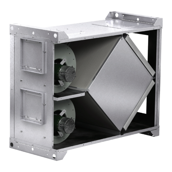
Model ERC-M
Energy Core Ventilator
Energy Core Ventilator
1
Advertisement
Table of Contents
Troubleshooting

Summary of Contents for valent ERC-M
-
Page 1: General Safety Information
Document 486437 Model ERC-M Energy Core Ventilator Installation, Operation and Maintenance Manual Please read and save these instructions for future reference. Read carefully before attempting to assemble, install, operate or maintain the product described. Protect yourself and others by observing all safety information. Failure to comply with these instructions will result in voiding of the product warranty and may result in personal injury and/or property damage. -
Page 2: Table Of Contents
Table of Contents Unit Overview General Safety Information ....1 Summer Operation Unit Overview ..... 2 Outdoor air is preconditioned (temperature and moisture Receiving, Handling, Storage . -
Page 3: Receiving, Handling, Storage
Receiving This product may have been exposed to road salt The unit should be stored at least 3½ in. (89 mm) off during transit. If so, immediately wash off all visible the floor. Clearance should be provided to permit air white residue from all exterior surfaces. -
Page 4: Dimensional Data And Weights
ERC-M2 component access. When mounted on its side, the ERC-M only requires access on one side of the unit. It is recommended that access is kept on the electrical input side. Minimum service clearance should be provided on... -
Page 5: Intake And Discharge Locations
Intake and Discharge Locations The ERC-M comes standard with end connections. Changing the Inlet Location The option for configurable intake and discharge Step 1 Remove the metal cover for optional inlet connections (shaded in below drawing) are available location by unfastening the four (4) sheet metal screws and can be interchanged based on application in holding it in place. -
Page 6: Installation
The system design and installation should follow accepted industry practices, such as described in the ASHRAE Handbook and SMACNA. As standard, the ERC-M is to be mounted in a horizontal orientation but can also be mounted on its side or a vertical position. - Page 7 POOR GOOD Installation POOR GOOD Ductwork Connections Base Mounting with Base Vibration Isolators Examples of poor and good fan-to-duct connections • The base isolators kit includes four (4) isolators, are shown. Airflow out of the fan should four (4) brackets and required hardware. be directed straight or curve the same direction as the •...
-
Page 8: Electrical Connections
Electrical Connections Frost Control Before connecting power to the unit, read and understand the following instructions and wiring Extremely cold outdoor air temperatures can cause diagrams. Complete wiring diagrams are attached inside moisture condensation and frosting on the energy the blower door of the unit. recovery core. -
Page 9: Mounting & Wiring
Mounting & Wiring HOA Controller Mounting ERV Control PCB GPN: 387192 HOA Wiring Energy Core Ventilator... -
Page 10: Energy Recovery Ventilator (Erv) Specifications
ERV Specifications Dual Mode Speed Control AC Input Power Place SW2 slide switch on ERV PCB to the dual mode. 1115Vac, 230Vac, 277Vac 50/60 Hz. Provide a 0-10Vdc command signal to Pin 7 (-) and Pin 8 (+), of TB2 for speed control of Motor A. Provide Motor and Aux Input another 0-10V command signal to Pin 9 (-) and Pin 10 115Vac —... -
Page 11: Hand/Off/Auto (Hoa) Control Troubleshooting
HOA Troubleshooting ERV Troubleshooting Guide Symptoms Potential Issues ¦ Loss of Input Power ¦ Check Breaker ¦ Incorrect wiring ¦ Check input power Wiring ¦ Green LED is not illuminated for Remote ¦ Validate correct Input Power to Terminal Block TB1 Unit is NOT operating ¦... -
Page 12: System Start-Up
System Start-Up DANGER Pre-Start-Up Checklist Electric shock hazard. Can cause injury or death. o Disconnect and lock-out all power switches Before attempting to perform any service or o Remove any foreign objects that are located in the maintenance, turn the electrical power to unit to OFF energy recovery unit. - Page 13 Check Blower Wheel Rotation Forward Curved After the ERC-M has been put into operation, an annual First, hand rotate the inspection and maintenance program should be set-up blower to ensure that to preserve reliability and performance.
-
Page 14: Routine Maintenance
Routine Maintenance Energy Recovery Core WARNING Fiber Membrane Do not use a high pressure water source (pressure Frequency of cleaning - A regular cleaning cycle must washer) or harsh, corrosive detergents. This will be established for the energy recovery core in order to result in a damaged core and will not be covered by maintain optimum sensible and latent energy transfer. - Page 15 Standard Components Vari-Green® Electronically Commutated Motor Features • Soft Start – All motors feature soft-start technology which eliminates inrush current at start-up. The motors will reliably start at any speed setting. • Overload Protection – If the motor becomes overloaded, it will automatically reduce its speed until it is no longer overloaded.
-
Page 16: Troubleshooting
Troubleshooting Symptom Possible Cause Corrective Action Check fuses/circuit breakers, replace if needed. Check for On/ Electrical Unit is NOT Off switches. Check for correct supply voltage. operating Motor Check motor horsepower is correct and not tripping overloads. Adjust wheel and/or inlet cone. Tighten wheel hub or bearing Fan wheel rubbing on inlet collars on shaft. -
Page 17: Maintenance Log
Maintenance Log Date ___________________Time _____________ AM/PM Date ___________________Time _____________ AM/PM Notes: ___________________________________________ Notes: ___________________________________________ _________________________________________________ _________________________________________________ _________________________________________________ _________________________________________________ _________________________________________________ _________________________________________________ _________________________________________________ _________________________________________________ Date ___________________Time _____________ AM/PM Date ___________________Time _____________ AM/PM Notes: ___________________________________________ Notes: ___________________________________________ _________________________________________________ _________________________________________________ _________________________________________________ _________________________________________________ _________________________________________________ _________________________________________________ _________________________________________________ _________________________________________________ Date ___________________Time _____________ AM/PM... - Page 18 Maintenance Log Date ___________________Time _____________ AM/PM Date ___________________Time _____________ AM/PM Notes: ___________________________________________ Notes: ___________________________________________ _________________________________________________ _________________________________________________ _________________________________________________ _________________________________________________ _________________________________________________ _________________________________________________ _________________________________________________ _________________________________________________ Date ___________________Time _____________ AM/PM Date ___________________Time _____________ AM/PM Notes: ___________________________________________ Notes: ___________________________________________ _________________________________________________ _________________________________________________ _________________________________________________ _________________________________________________ _________________________________________________ _________________________________________________ _________________________________________________ _________________________________________________ Date ___________________Time _____________ AM/PM...
- Page 19 Maintenance Log Date ___________________Time _____________ AM/PM Date ___________________Time _____________ AM/PM Notes: ___________________________________________ Notes: ___________________________________________ _________________________________________________ _________________________________________________ _________________________________________________ _________________________________________________ _________________________________________________ _________________________________________________ _________________________________________________ _________________________________________________ Date ___________________Time _____________ AM/PM Date ___________________Time _____________ AM/PM Notes: ___________________________________________ Notes: ___________________________________________ _________________________________________________ _________________________________________________ _________________________________________________ _________________________________________________ _________________________________________________ _________________________________________________ _________________________________________________ _________________________________________________ Date ___________________Time _____________ AM/PM...
- Page 20 ERC-M Manual Part number:486437 Rev. 1 © 2023 Valent November 2023 Continuous product improvement is a policy of Valent; therefore, product functionality and specifications are subject to change without notice. For the most recent product information visit the product website.