Danby DPTA090HEB1WDB, DPTA120HEB1WDB, DPTA150HEB1WDB - Packaged Terminal Manual
- Owner's manual (37 pages)
Advertisement
INSTALLATION INSTRUCTIONS
DIMENSIONS
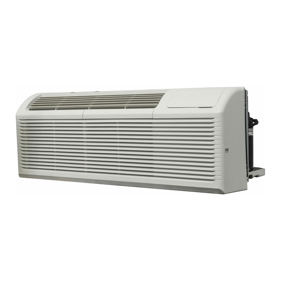
This appliance is 42 inches (106.7 cm) wide, 16 inches &40.8 cm) high and 23.9 inches (60.6 cm) deep.

WALL SLEEVE
All wall sleeves used to install the air conditioner must be in good structural condition and have a rear grille that securely attaches to the sleeve or the flange of the sleeve to secure the appliance.
Install the wall sleeve according to the wall sleeve installation instructions. When Installing the sleeve make certain there is nothing within 25 inches (50.8 cm) of the back of the appliance that would interfere with heat radiation and exhaust air flow.
INSTALLATION
- Remove the front panel. Pull out from the bottom to release it from the tabs and then lift up.

- Remove the shipping screw from the vent door.

- Rotate the vent control lever to either open or close the vent door. When the vent control lever is set to "close", only the air inside the room is circulated. When the vent control lever is set to
![]() 'open", outdoor air will be drawn into the room. This can reduce heating or cooling efficiency.
'open", outdoor air will be drawn into the room. This can reduce heating or cooling efficiency.

- Lift the appliance and slide it into the wall sleeve until it is set firmly against the front wall of the sleeve and secure With four screws through the flange holes.

- Reinstall the front panel. Place the tabs over the top rail and push Inward at the bottom until the panel snaps Into place.


DIP SWITCHES
Dip switch controls are located behind the front panel through an opening below the control panel. Remove the front panel to access the dip switches.
Dip switches are accessible without opening the control box.
The appliance should be unplugged before making adjustments to the dip switches.
DIP SWITCH CONFIGURATIONS
See the table below for dip switch configurations and functions.

| Number | UP (ON) | DOWN (OFF) | Remarks |
| S1 | Electric heat only | Electric and pump heat | Heat pump model only |
| S2 | Temperature display O F | Temperature display oc | |
| S3 | Wall thermostat enable | Control panel enable | |
| S4*S5 | UP*UP: 61 0 F 86 0 F (l CC 300C) UP*DOWN: 650 F 780 F 26 0C DOWN*UP: 630 F 170c 270c DOWN*DOWN: 68 0 F 750 F (200C 240C) | Configuration of S4 and S5 combine to select set point range | |
| S6 | Fan continuous run for heating | Fan cycle for heating | |
| S7 | Fan continuous run for cooling | Fan cycle for cooling | |
| S8 | Low temperature protection enable | Low temperature protection disable | |
| S9 (S3 UP) | Use some types of wall thermostat | Use PTAC other wall thermostat | Consult with sales agent or manufacturer for details |
| S9 (S3 DOWN) | Use control panel only | Use control panel or some types of wall thermostat | |
| Sw11 | Load delay for 3 seconds | Normal | Optional |
DIP SWITCH CONFIGURATIONS BY PANEL CONTROL
- Turn off the appliance.
- Press and hold the increase and decrease buttons at the same time for 3 seconds to activate the dip switch configuration by panel control.
- See the table below for dip switch configurations and functions by panel control.
- The display will show numbers. The high left number is for dip switches, the low right number is for functions.
- Press the increase button to set the dip switches. Press the decrease button to set the functions.
- Press and hold the increase and decrease buttons at the same time for 3 seconds to confirm choices. The appliance will return to regular functioning after 30 seconds with no input.
Note: The LED display window will show "00" when first entering setting mode. Set switches in sequence one at a time.
Note: To activate front desk control function, set dip switch SW7 to "DOWN(OFF)" and then set the panel control to "AO".
| Number | High (left) | Low (right) | Remarks | |
| / | 0 | 1 - by panel control | 0 - by dip switches | |
| S1 | 1 | 1 - electric heat only | 0 - electric and pump heat | Heat pump model only |
| S2 | 2 | 1 - °F display | 0 - °C display | |
| S3*S9 | 3 | 3 - use control panel or some types of wall thermostat 2 - use some types of wall thermostat 1 - use PTAC other wall thermostat 0 - use control panel | Consult with sales agent or manufacturer for details | |
| S4*S5 | 4 | 4 - 62°F ~ 86°F (17°C ~ 30°C) 3 - 61°F ~ 86°F (16°C ~ 30°C) 2 - 65°F ~ 78°F (18°C ~ 26°C) 1 - 63°F ~ 80°F (17°C ~ 27°C) 0 - 68°F ~ 75°F (20°C ~ 24°C) | ||
| S6 | 6 | 1 - continuous fan for heating | 0 - fan cycle for heating | Not available for "use PTAC other wall thermostat" |
| S7 | 7 | 1 - continuous fan for cooling | 0 - fan cycle for cooling | |
| S8 | 8 | 1 - low temperature protection enable | 0 - low temperature protection disable | Optional |
| SW7 | A | 1 - front desk control enable | 0 - front desk control disable | Optional |
| Sw11 | B | 1 - load delay for 3 seconds | 0 - normal | Optional |
WALL THERMOSTAT TERMINAL
Note: Using a wall thermostat is optional.

Only trained, qualified personnel should access the electrical panel on the appliance and install electrical accessories. Contact a local electrical contractor, dealer or distributor for assistance.
Thermostat Wire Routing
Thermostat wire is field supplied. Recommended wire gauge is 18 to 20 gauge solid thermostat wire.
Note: It is recommended that extra wires are run to the appliance in case any are damaged during installation. Thermostat wire should always be routed around or under, never through the wall sleeve. The wire should be routed behind the front panel to the easily accessible terminal connector.
Pull the dip switch to the DOWN(OFF) position.
Insert the wire connector of the wall thermostat into the relevant terminal according to the different shapes as shown.

- Dip switch
- Terminal
PTAC Other Wall Thermostat
Remove the screws as shown and take the cover panel down.

Terminal of PTAC other wall thermostat (MODE A)

Terminal of PTAC other wall thermostat (MODE B)


Failure to follow this caution may result in equipment damage or improper operation.
Improper wiring may damage the electronics. Common busing is not permitted. Damage or erratic operation may result.
FRONT DESK CONTROL
Note: Using the front desk control is optional.
The controller can handle a switch signal from FC(L) and FC(N) input, called front desk control. Input must be 24VAC. If the system does not receive a 24VAC signal it will turn off; otherwise the appliance runs in normal control. The dip switch can control the front desk control feature. If the dip switch is in the down position, the appliance will turn off, otherwise it will run as normal.

ADDITIONAL REQUIREMENTS
- Use 4-way terminal for heat pump connection only.
- Wall thermostat must be heating changeover 4-way valve.
- For thermostats that have only one fan speed output (on or auto) the fan speed is determined by how the terminal connector is wired. If low fan is desired, wire the G output from the thermostat to (LOW-FAN) on the appliance's terminal block. If high fan is desired, wire the G output from the thermostat to (HI-FAN) on the appliance's terminal block.
- The range of set temperature of wall thermostat must be in consonance with the range of dip switch setting.
- Wall thermostat must be set the type properly in consonance with the appliance type; heat pump or no heat pump.
- If the wall thermostat has only one electrical heater output, connect the two terminals of HEAT 1 and HEAT 2, the appliance can operate two electrical heaters (only if the appliance has two electrical heaters). Otherwise operate one electrical heater.
- Do not remove the control panel.
- If the appliance is being controlled by a wall mounted thermostat, place the provided cover over the control panel as per the below.
Note: When the display shows "LC" it means the buttons on the control panel are not available and the appliance should be controlled by the wall mounted thermostat that it is connected to.

This unit is controlled by a wall mounted thermostat
OPERATING INSTRUCTIONS
CONTROL PANEL

- Remote control receiver
- Display Panel: Displays the set temperature. When in fan mode, displays the ambient temperature. To change the temperature scale being displayed, press and hold the up and down buttons at the same time for three seconds.
- Fan Button: Used to set the fan speed. The fan can be set to low, medium, and high. The lights will indicate the chosen fan speed.
- Continuous fan button: In cooling mode, press to set the fan to run continuously.
- Increase and decrease buttons: Used to adjust the set temperature in 1° increments.
- Mode button: Used to choose the operating mode. The lights will indicate the chosen mode, cool, heat or fan.
- Power button: Used to turn the appliance on or off.
OPERATING MODES
There are three operating modes to choose from. Press the Mode Button repeatedly to choose the desired mode. The adjacent indicator light will illuminate to show which mode has been selected.
- Cool Mode
Choose cool mode to set the cooling function. Use the up and down buttons to choose the desired temperature. When cool mode is selected, the fan speed can be adjusted by pressing the fan button. - Heat Mode
Choose heat mode to set the heating function. Use the up and down buttons to choose the desired temperature. - Fan Mode
Choose fan mode to run the internal fan without engaging the cooling function. Press the fan button repeatedly to choose the fan speed, low, med or high.
CARE & MAINTENANCE
AIR FILTER
The air filter should be cleaned approximately every 2 weeks. The air filter may require more frequent cleaning if there is significant dander or fur in the air.
The air filter is located behind the front intake grill. Grasp the filter by the center and pull up and out.
Use a vacuum cleaner with a soft brush attachment to remove any large debris or dust build up from the air filter.
Wash the filter in lukewarm, soapy water, below 400C (1 040 F), or use a neutral cleaning agent.
Rinse the filter with clean water and dry thoroughly before reinstalling in the appliance.
Note: Do not operate the appliance without the air filter installed.

CLEANING
To avoid possible electric shock, ensure that the appliance is unplugged before performing any cleaning or maintenance.
The outside of the appliance can be wiped clean with a soft cloth or With a lukewarm, damp cloth if necessary.
Do not use gasoline benzene, thinner or any other chemicals to clean this appliance as these substances can cause damage to the finish and deformation of plastic parts.
Never pour water directly onto the appliance as this will cause deterioration of electrical components and wiring insulation.
ERROR CODES
If any of the below error codes appear on the display, unplug the appliance and then plug it back in. If the error code persists, call for service.
AS - room temperature sensor error
ES - evaporator temperature sensor error
CS - condenser temperature sensor error
OS - outside temperature sensor error
HS - exhaust temperature sensor error
LE - wire controller error
LO - room temperature is lower than OOC / 320 F
HI - room temperature is higher than 37oc / 990 F
FP - low temperature protection
TROUBLESHOOTING
Danby Consumer Care: 1-800-263-2629
Hours of operation:
Monday to Thursday 8:30 am - 6:00 pm Eastern Standard Time
Friday 8:30 am - 4:00 pm Eastern Standard Time
Information in this manual is subject to change without notice.
| PROBLEM | POSSIBLE CAUSE |
Appliance will not operate |
|
Insufficient cooling |
|
Noise |
|
Odors |
|
Water dripping inside |
|
Water dripping outside |
|
Frost build up |
|
Important Safety Information
READ AND FOLLOW ALL SAFETY INSTRUCTIONS
ELECTRICAL REQUIREMENTS
All wiring must comply with local and national codes and must be installed by a qualified electrician. Check the available power supply and resolve any wiring problems before installing and operating this appliance.
This 230 V appliance may be used in any properly wired, general purpose household receptacle. The rating plate located on the right side of the appliance lust above the power cord contains electrical and other technical data.
SAFETY INSTRUCTIONS
This appliance is not intended for use by persons, including children, with reduced physical, sensory or mental capabilities or lack of experience and knowledge, unless they have been given supervision or instruction concerning use of the appliance by a person responsible for their safety.
Children should be supervised to ensure that they do not play with the appliance.
Do not install the appliance where leakage of combustible gas is suspected.
POWER CORD INSTRUCTIONS
The power supply cord contains a current device that senses damage to the power cord. To test the power supply cord:
- Press the TEST button on the power supply cord.
The RESET button will click and pop out. - Press the RESET button until it clicks into place.
- The power supply cord is now supplying electricity to the appliance.
Do not use this device to turn the appliance on or off. Ensure that the RESET button is pushed in for correct operation. The power supply cord must be replaced if it fails to reset when the TEST button is pushed.
GROUNDING INSTRUCTIONS
This appliance must be grounded. Grounding reduces the risk of electrical shock by providing an escape wire for the electrical current.
This appliance has a cord that has a grounding wire with a 3-prong plug. The power cord must be plugged into an outlet that is properly grounded. If the outlet is a 2-prong wall outlet It must be replaced with a properly grounded 3-prong wall outlet.

Improper use of the grounding plug can result In a risk of electric shock. Consult a qualified electrician or service agent if the grounding instructions are not completely understood, or If doubt exists as to whether the appliance is properly grounded.
Do not connect your appliance to extension cords or together with another appliance in the same wall outlet. Do not splice the power cord. Do not under any circumstances cut or remove the third ground prong from the power cord. Do not use extension cords or ungrounded (two prongs) adapters.
If the power supply cord is damaged, it must be replaced by the manufacturer, its service agent or similar qualified person in order to avoid hazard.
SAVE THESE INSTRUCTIONS!
www.Danby.com

DANBY PRODUCTS LIMITED, ONTARIO, CANADA N I H 6Z9
DANBY PRODUCTS INC. FINDLAY, OHIO, USA 45840

Documents / Resources
References
Download manual
Here you can download full pdf version of manual, it may contain additional safety instructions, warranty information, FCC rules, etc.
Download Danby DPTA090HEB1WDB, DPTA120HEB1WDB, DPTA150HEB1WDB - Packaged Terminal Manual
Advertisement


Need help?
Do you have a question about the DPTA090HEB1WDB and is the answer not in the manual?
Questions and answers