
Summary of Contents for MYTORQ MY-CURRENT
- Page 1 MY-CURRENT User Manual Model: MY-CURRENT SAING EI CORP. https://www.mytorqtools.com. Y2F233-4E-001 20230512...
-
Page 2: Table Of Contents
………………………………………………………………………………..……10 OOLS AND DATA 8. D ………………………………………………………….….10 ESCRIPTION OF DISPLAY STATUS CODES 9. D ……………………………………….…….12 ESCRIPTION OF EXTERNAL OUTPUT CONTROL FUNCTION 10. D …………………………………………..……13 ESCRIPTION OF EXTERNAL INPUT CONTROL FUNCTION 11. MY-CURRENT ………...14 DATA TRANSMISSION INSTRUCTIONS AND SEQUENCE CONTROL SUGGESTIONS... -
Page 3: Important Safety Instructions
7. Do not use the power cord to pull the current controller and power supply or pull the power cord away from the socket. Precaution 意 series MY-CURRENT 1. Use this controller with a set of dedicated current control screwdrivers screwdrivers. -
Page 4: Product Specification
3.46kg Screwdriver model No. series MY-CURRENT 1.2 Operation 1. Read the User Manual carefully before operation and operate the current controller according to the safety regulations. 2. When inserting or unplugging the screwdriver cable and the plug of the power cord, it must grasp the plug part of the cable. -
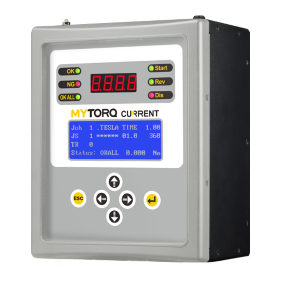
Page 5: Appearance
3. Appearance 3.1 Panel 1. OK signal indicator 7. Start signal indicator 2. NG signal indicator 8. Reverse signal indicator 3. OKALL signal indicator 9. Disable signal indicator 4. 4-position, 7-sect torque display 10. 16X4 LCM display setting 5. ESC button (return/exit/enter setting mode) 11. -
Page 6: Bottom
3.2 Bottom 1. Micro SD card socket (data storage) 6. Voltage changeover switch 2. Protocol output port 7. Scanner USB type-A socket 3. Software-updating socket 8. Wired communication port 4. Tool connection seat 9. Output screwdriver signal port 5. Power cord socket and power switch 10. -
Page 7: Lcm Display
3.4 LCM display 1. Display currently underway job 2. Display current underway sequence 3. Display remaining number of screws 4. Display current system status 5. Display tool actuation time (seconds) 6. Display tool actuating circle number 7. Display tool actuation angle 8. -
Page 8: Controller Setting
5. Controller setting Name Data setting item Function description Default value Controller mode Single Online mode Single Single: Single mode Equipment No. 001~250 Set equipment number Tool activation Press start/external Select tool activation method Both setting start/both Baud setting 115200/57600/38400 Select the baud of controller’s data transmission 115200 /19200/9600... -
Page 9: Jobs And Sequences
Set product serial Product serial Display the product serial number of the device Product serial number number number Change password 0000~9999 Set password 0000 Data export Wireless/wired Select data output by wireless network or wired RS-232 settings network/RS-232 network Sound mode ON/OFF Set the buzzer switch Select a language Chinese/English... - Page 10 Torque Target torque Set the target torque value, delay time or target angle value of the The lower limit Target/Delay value (kgf.cm) screwdriver. of target torque Time/Angle 000.00~550.00 The target torque value must be entered in a reasonable torque value follows the Target (006.00~030.00) range according to the specification of the screwdriver.
-
Page 11: Tools And Data
OKALL OFF/ON Set the processing method selected when the total number of prohibits the screws in the sequence is counted and the action is completed. screwdriver from starting On: Lock the screwdriver immediately when the number of pieces in the sequence is completed. User needs to press the "ENTER"... - Page 12 When the "prohibition to start when the sequence is completed" & "sensor External sensor mode mode trigger-once sense" is turned on; Trigger once + panel Enter the LCM screen will display "C4" when OKALL key / CONFIRM key for external switch When the "prohibition to start after sequence completion"...
-
Page 13: Description Of External Output Control Function
9. Description of external output control Description Connector Definition Ordinary load Inductive load CN13 CN13 RUN FWD: CN 1 START CN1 and CN2 are connected when a screwdriver is initiated. CN1 + CN2 are connected when short-circuited. CN 2 CN1 + CN2 are disconnected when open-circuited CN 3 CN 4 CN13... -
Page 14: Description Of External Input Control Function
10. Description of external input control Description Connector Definition 1. Screwdriver starts to rotate when CN1+CN2 are short-circuited Input external start signal CN 1 (CLOSE). START_IN 2. Screwdriver stops rotating when CN1+CN2 are open-circuited CN 2 (OPEN). 1. The external reverse signal CN3+CN4 is first short-circuited (CLOSE), and when the start signal CN1+CN2 is short-circuited Input external reverse signal (CLOSE), the screwdriver begins to reverse-start... -
Page 15: My-Current Data Transmission Instructions And Sequence Control Suggestions
11. TCC data transmission instructions and sequence control suggestions VER:20220606 1. Controller booting and time synchronization: After the controller is turned on, it will automatically send {REQ100,..} data format every second to notify the externally connected devices (computer, PLC, and AMS, etc.); at this moment, it is necessary to reply {CMD100,..} indicating that the controller has been booted normally and the current time of the controller. - Page 16 Circulated communication Controller writes to host REQ100 (sent per second) Controller Host PC/AMS/PLC (Master) Host response time (Slave) CMD100 (sent per second) Barcode communication Input barcode to host REQ101 Host Controller PC/AMS/PLC Host response time (Slave) (Master) CMD100 Transmittal of torque deviation during lock Write data to host DATA101 (screwdriver is running) Note: It won’t stop until screwdriver status is generated)
Need help?
Do you have a question about the MY-CURRENT and is the answer not in the manual?
Questions and answers